
I received a number of enquiries for plans for that engine, but the design for that air engine wasn't really one that lent itself to building from plans. So I came up with a better design for my air engine 2.
I first built the air engine shown here in 2009, but didn't make a video of its actual construction. In 2017, I built it again to make video of the process.
A video presenting the air engine I built in 2009.
My first air engine was made mostly from solid maple. Over the course of many
years, some of the pieces in the valve assembly and cylinder warped just slightly,
and I had to sand them down a bit to get the engine to run freely again.
For this engine, I made the cylinder and valve assembly out of
baltic birch plywood - the kind of plywood that is made of layers of birch throughout.
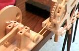
 One of the trickiest bits of the engine is making the crankshaft. The main crank
for the engine is actually directly off the flywheel, but a secondary crank is
needed to actuate the sliding valve assembly.
This secondary crank only has a 6 mm throw to it, so I could make it by gluing
another piece of dowel to the main shaft. The second piece of dowel is carved to a
crescent shaped cross section to allow it to fit neatly against the shaft.
After that, I cut away part of the main shaft.
One of the trickiest bits of the engine is making the crankshaft. The main crank
for the engine is actually directly off the flywheel, but a secondary crank is
needed to actuate the sliding valve assembly.
This secondary crank only has a 6 mm throw to it, so I could make it by gluing
another piece of dowel to the main shaft. The second piece of dowel is carved to a
crescent shaped cross section to allow it to fit neatly against the shaft.
After that, I cut away part of the main shaft.
The initial cut away was made with a band saw, but the rest I carefully carved out by hand.
 I made a guide to check how much to cut away. The guide is made by drilling a
hole on the edge of a piece of plywood, then cutting away half of the hole.
I used this to check how much I still needed to cut away as I was whittling
the main part of the shaft down.
I made a guide to check how much to cut away. The guide is made by drilling a
hole on the edge of a piece of plywood, then cutting away half of the hole.
I used this to check how much I still needed to cut away as I was whittling
the main part of the shaft down.

 By pressing my guide firmly against the carved away section, and turning back and forth,
I could always see the glossy sections where my guide had rubbed against the shaft,
and used that as a guide for where to remove material.
By pressing my guide firmly against the carved away section, and turning back and forth,
I could always see the glossy sections where my guide had rubbed against the shaft,
and used that as a guide for where to remove material.
 Once I was satisfied that the middle part of my crankshaft was sufficiently round,
I made two reinforcing plates to glue on either side of it. I made these by drilling
two 5/8" holes with centers 6 mm apart. After drilling the holes, I cut out a small rectangle
around the holes, and glued it on to the crank. Gluing the pieces on was a simple matter
of sliding it on from the ends of the crank.
Once I was satisfied that the middle part of my crankshaft was sufficiently round,
I made two reinforcing plates to glue on either side of it. I made these by drilling
two 5/8" holes with centers 6 mm apart. After drilling the holes, I cut out a small rectangle
around the holes, and glued it on to the crank. Gluing the pieces on was a simple matter
of sliding it on from the ends of the crank.
 The finished crankshaft (after varnishing)
 The crankshaft bearings blocks are made of two pieces. To make sure the holes were all
lined up perfectly, I clamped the two halves of the bearing together, and then drilled
the screw holes through them.
The crankshaft bearings blocks are made of two pieces. To make sure the holes were all
lined up perfectly, I clamped the two halves of the bearing together, and then drilled
the screw holes through them.
 After screwing the top part of the bearing block on, I drilled the shaft hole
through both parts.
I used my biggest 5/8" drill. That is, the one of my 5/8" drills that seems to drill 5/8"
holes that fits 5/8" dowels the loosest, so it's a tiny bit over 5/8".
After drilling the holes, I finally cut out the whole bearing block with a band saw,
and rounded the corners on it.
After screwing the top part of the bearing block on, I drilled the shaft hole
through both parts.
I used my biggest 5/8" drill. That is, the one of my 5/8" drills that seems to drill 5/8"
holes that fits 5/8" dowels the loosest, so it's a tiny bit over 5/8".
After drilling the holes, I finally cut out the whole bearing block with a band saw,
and rounded the corners on it.
 I used the same approach for making the holes in the connecting rod for the valve slider.
First screw the pieces together, then drill a hole in the assembled connecting rod.
I used the same approach for making the holes in the connecting rod for the valve slider.
First screw the pieces together, then drill a hole in the assembled connecting rod.
 I did end up tweaking the bearings just a little bit, by carving out a very thin layer
from the insides with a carving knife. I had to do this again after I varnished all
the parts, as the varnish added a little bit of thickness everywhere. But I wanted to
varnish even the bearing surfaces, so that when I'd put a few drops of oil on them, hopefully
the oil would not soak into the wood too much.
I did end up tweaking the bearings just a little bit, by carving out a very thin layer
from the insides with a carving knife. I had to do this again after I varnished all
the parts, as the varnish added a little bit of thickness everywhere. But I wanted to
varnish even the bearing surfaces, so that when I'd put a few drops of oil on them, hopefully
the oil would not soak into the wood too much.
 The "cylinder" and piston are simply made square. To make them round would perhaps
look more realistic, but I doubt I would have been able to make it very accurately. Also,
I would have had to use a piece of solid wood to cut it out of, which would
then be subject to slight warping over the years.
The "cylinder" and piston are simply made square. To make them round would perhaps
look more realistic, but I doubt I would have been able to make it very accurately. Also,
I would have had to use a piece of solid wood to cut it out of, which would
then be subject to slight warping over the years.
There are no piston rings or seals around the piston, so there is quite a bit of "blow by". But this engine is not designed to be very powerful or efficient, so it's OK. In fact, ideally, there would be a slight gap around the piston to reduce friction, on the order of about 0.1 mm. I cut the piston to have no clearance at all, and then sanded it to fit. This was an iterative process.
There are no gaskets in the assembly. Just screwing the pieces together closes the gap sufficiently to reduce leakage to acceptable levels - certainly, there is much less leakage around the cover than there is around the piston.
 In the previous photo, you can see holes in the back of the cylinder, which are for
the air inlets. The air inlets for the piston need to be towards the ends of the piston, but
the valve assembly needs the inlets together, so an internal channel is formed
between two plywood parts, by carving a cavity out of the plywood.
I just roughed these out with a big forstner bit - the cavities are not visible
with the engine assembled, so it's not critical.
In the previous photo, you can see holes in the back of the cylinder, which are for
the air inlets. The air inlets for the piston need to be towards the ends of the piston, but
the valve assembly needs the inlets together, so an internal channel is formed
between two plywood parts, by carving a cavity out of the plywood.
I just roughed these out with a big forstner bit - the cavities are not visible
with the engine assembled, so it's not critical.
 This photos shows all the pieces of the piston and valve assembly. The two
holes in the front-most piece of plywood are the air inlet and exhaust. By
changing which inlet one blows (or sucks) on, the engine will run in the opposite
direction.
This photos shows all the pieces of the piston and valve assembly. The two
holes in the front-most piece of plywood are the air inlet and exhaust. By
changing which inlet one blows (or sucks) on, the engine will run in the opposite
direction.
All the pieces of the valve assembly are varnished. To keep the varnish smooth and level, I scraped the varnish between coats. A bit of light sanding was required after all was done as well to get the valves sliding easily again.
The whole assembly is put together with 3/4" #4 wood screws, 38 screws in all.

 For the bearing on the crank, I used a 1.5" long screw with a shank with no thread on it.
I had to cut the end of the screw off so it would not stick out of the other side of
the flywheel by too far. I actual found an old style wood screw with a thicker shank in my
collection (screw on the bottom).
Newer screws have a shank that is just thinner than the thread, which would mean
that the connecting rod would have a little bit of play on the shank.
For the bearing on the crank, I used a 1.5" long screw with a shank with no thread on it.
I had to cut the end of the screw off so it would not stick out of the other side of
the flywheel by too far. I actual found an old style wood screw with a thicker shank in my
collection (screw on the bottom).
Newer screws have a shank that is just thinner than the thread, which would mean
that the connecting rod would have a little bit of play on the shank.
 The piston end of the connecting rod is joined to the piston shaft with a simple steel
pin, which is just a cut off nail.
The hole in the piston shaft is drilled slightly undersize so that the pin sits firmly
in the piston shaft. The holes to the connecting rod are slightly oversized, allowing the
connecting rod to pivot freely on the pin.
The piston end of the connecting rod is joined to the piston shaft with a simple steel
pin, which is just a cut off nail.
The hole in the piston shaft is drilled slightly undersize so that the pin sits firmly
in the piston shaft. The holes to the connecting rod are slightly oversized, allowing the
connecting rod to pivot freely on the pin.
 The whole engine mounts on a piece of plywood.
I made the flywheel as large as I could for this engine, which required cutting a slot out of the mounting plate for it to protrude into. I was about to start chiseling the slot for the flywheel in the base plate, when I realized that my flywheel was just a little smaller than a skillsaw blade, so I just made multiple cuts with a skillsaw blade in the plywood to carve out the cavity. I made these cuts by clamping a block to the fence to keep the plywood from sliding backwards, and just cranking the spinning blade up into the plywood.
 I built the whole engine, and made sure it ran smoothly before varnishing all the pieces.
The photo at left shows the pieces drying after I brushed on the final coat.
I built the whole engine, and made sure it ran smoothly before varnishing all the pieces.
The photo at left shows the pieces drying after I brushed on the final coat.
Varnishing the engine necessitated further tweaking to get the engine to run smoothly again. But with this engine essentially being a toy, there is an expectation that it would get handled a fair bit, and so if it's varnished, it's much easier to get it clean again. Also, the varnish I used is fairly slippery, so it should make the engine run more easily.
 The varnish itself however was not quite slippery enough, and I ended up oiling the
crankshaft a little bit, to keep it from squeaking. In my
previous air engine,
I used axle grease on the bearings and no varnish. This made them run really
smoothly, but the whole thing is a bit messy. The 3 in one household oil is much cleaner.
The varnish itself however was not quite slippery enough, and I ended up oiling the
crankshaft a little bit, to keep it from squeaking. In my
previous air engine,
I used axle grease on the bearings and no varnish. This made them run really
smoothly, but the whole thing is a bit messy. The 3 in one household oil is much cleaner.
After Donald Zorn built his engine and was able to
spin it up to 1050 RPM, I experimented to
see how fast I might be able to spin my air engine up to.

I have drawn up some very detailed plans for this engine, which should make it much easier to build such an engine if you wish to do so.
 You can buy plans
 Air engine 1
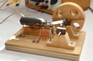 Solenoid engine
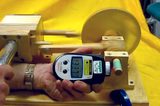

 The slinky machine
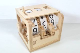 Mechanical counter
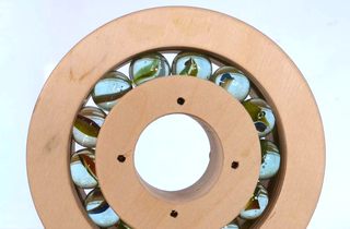 Wooden ball bearing