Larry Paulsen writes:
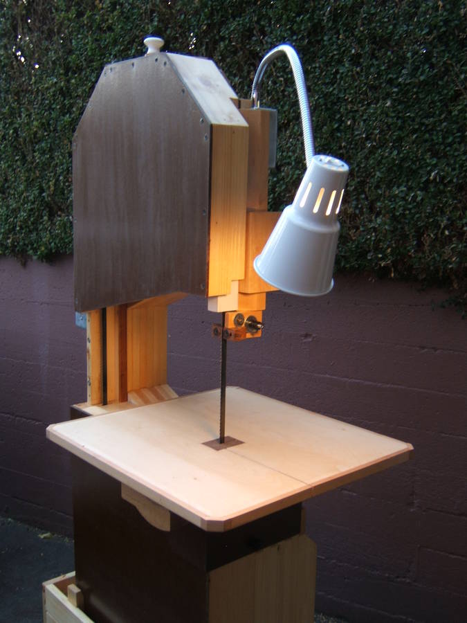
Dear Matthias,My brother and I have really enjoyed making our bandsaw from your plans, which my wife (thoughtful woman) gave to me for my birthday. My brother Rick and I live in Seattle, and share a lot of tools, but neither of us has a bandsaw, so it was the perfect project for us to do together. We thought you might like to see how it turned out. We used double-faced tempered hardboard for the places where you call for 1/4" ply. Looks nice, and it sheds sawdust really well, which is great for a dust enclosure. We also added an industrial sewing machine lamp for spot illumination.
Those and the hardware parts (blade, nuts, bolts, knobs, shafts and bearings) were the only full-price materials in our saw. Everything else was reuse or salvage: the spruce was offcuts from another guy's project, the hardwood was from reworked salvaged trim, the finish materials were leftovers -- even the plywood for the wheels (1/2" Baltic birch) was on a 50% off sale. The motor was a salvaged tablesaw motor which I found on Craigslist. Some of the bits and pieces came from our local building salvage source, the ReStore, and some of it from my stockpile of scrap.
We had a lot of fun producing jigs in the process of making this saw, too. Not as pretty as the ones on your website, of course, since we used scrap -- but they did a great job, and were so useful I'm keeping them around.
We departed from your method of producing some of the parts, though, and we thought you might be interested in the way we did those things: assembling and gluing up the frame, truing
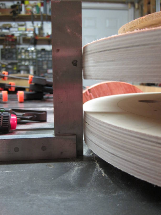
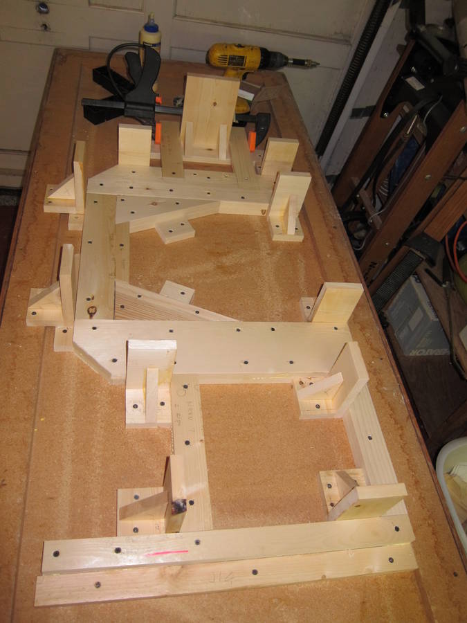 We were really interested in getting the frame truly flat and square at glue-up,
so after cutting the frame parts, we constructed a bunch of setup squares from
the scrap. (see below -- these also came in really handy a number of times later.)
We laid out the frame on the underside of a piece of salvaged countertop and
screwed down the squares to trap the pieces as we glued up the frame layers.
We'd set up a layer, screw it to the layer beneath, remove the screws, spread
the glue between the layers, then replace the screws, which were placed to act
as clamps. Then once the glue had dried , we removed the screws, then repeated
the process with each layer until we were done. This method resulted in a
frame that needed almost no truing at all
We were really interested in getting the frame truly flat and square at glue-up,
so after cutting the frame parts, we constructed a bunch of setup squares from
the scrap. (see below -- these also came in really handy a number of times later.)
We laid out the frame on the underside of a piece of salvaged countertop and
screwed down the squares to trap the pieces as we glued up the frame layers.
We'd set up a layer, screw it to the layer beneath, remove the screws, spread
the glue between the layers, then replace the screws, which were placed to act
as clamps. Then once the glue had dried , we removed the screws, then repeated
the process with each layer until we were done. This method resulted in a
frame that needed almost no truing at all
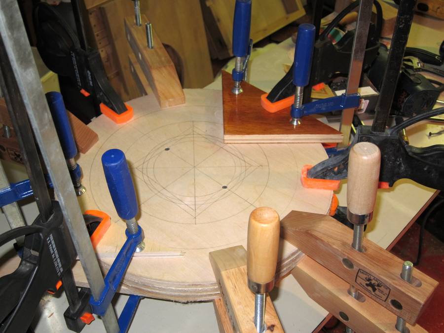 We took a lot of care laying out the wheels, marking every point that matters
when cutting them out and especially the references for mounting the bearings.
We marked all the wheel blanks the same, so we could take the inevitable bit
of warp in our sheet of ply into account and still know there would be
accurate marks on both faces. We used a router and trammel to cut them out.
Since they were all perfectly round and all exactly the same size, it
simplified glue-up quite a bit. We used the same gluing technique we
used on the frame on the middle layer of each wheel, but clamped the
outer layer to avoid visible screw holes.
We took a lot of care laying out the wheels, marking every point that matters
when cutting them out and especially the references for mounting the bearings.
We marked all the wheel blanks the same, so we could take the inevitable bit
of warp in our sheet of ply into account and still know there would be
accurate marks on both faces. We used a router and trammel to cut them out.
Since they were all perfectly round and all exactly the same size, it
simplified glue-up quite a bit. We used the same gluing technique we
used on the frame on the middle layer of each wheel, but clamped the
outer layer to avoid visible screw holes.
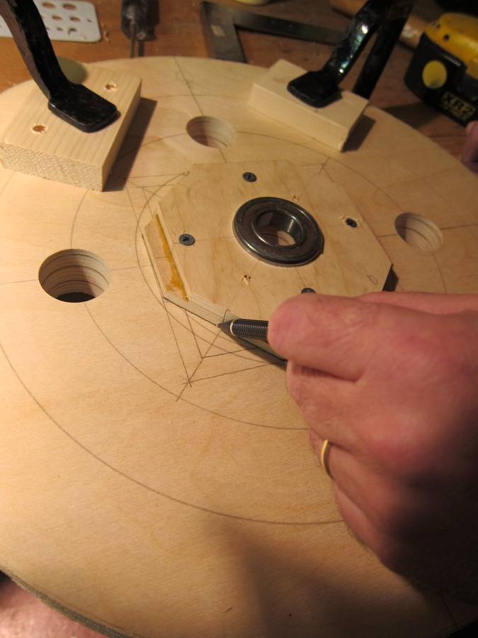 We spent extra time making sure the central hole in each wheel was
placed and cut accurately, and that the bearing flanges were placed so
the shafts were exactly perpendicular to the surface of the wheel: an
effort which paid off when it came time to true the wheels. We used the
same screwing-then-gluing technique we'd used laying up the frame, so
the flanges didn't slide around on us in the glue-up.
We spent extra time making sure the central hole in each wheel was
placed and cut accurately, and that the bearing flanges were placed so
the shafts were exactly perpendicular to the surface of the wheel: an
effort which paid off when it came time to true the wheels. We used the
same screwing-then-gluing technique we'd used laying up the frame, so
the flanges didn't slide around on us in the glue-up.
 Neither of us is a turner, and when we got the first wheel mounted to
the bench and connected to the motor in order to true the edges, it made
us nervous, so we backed off and decided to do it a different way.
After trying the method we used, we liked it so much we thought we'd
tell you about it:
Neither of us is a turner, and when we got the first wheel mounted to
the bench and connected to the motor in order to true the edges, it made
us nervous, so we backed off and decided to do it a different way.
After trying the method we used, we liked it so much we thought we'd
tell you about it:
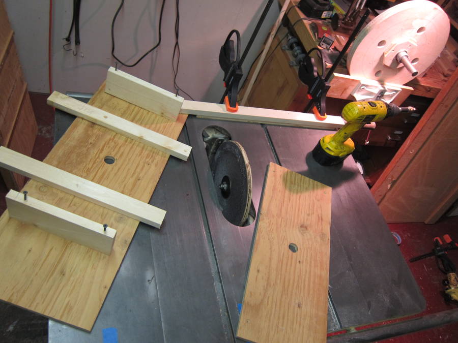
First, we cut out a 10 inch circle of ply using a simple jig on the table saw, drilled a 5/8 hole through the middle, plastered a sanding disc to it, and mounted it to the table saw. This gave us a disc sander with a big flat table and the ability to tilt the sanding disc to any angle we wanted.
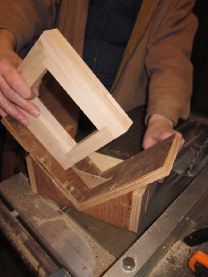
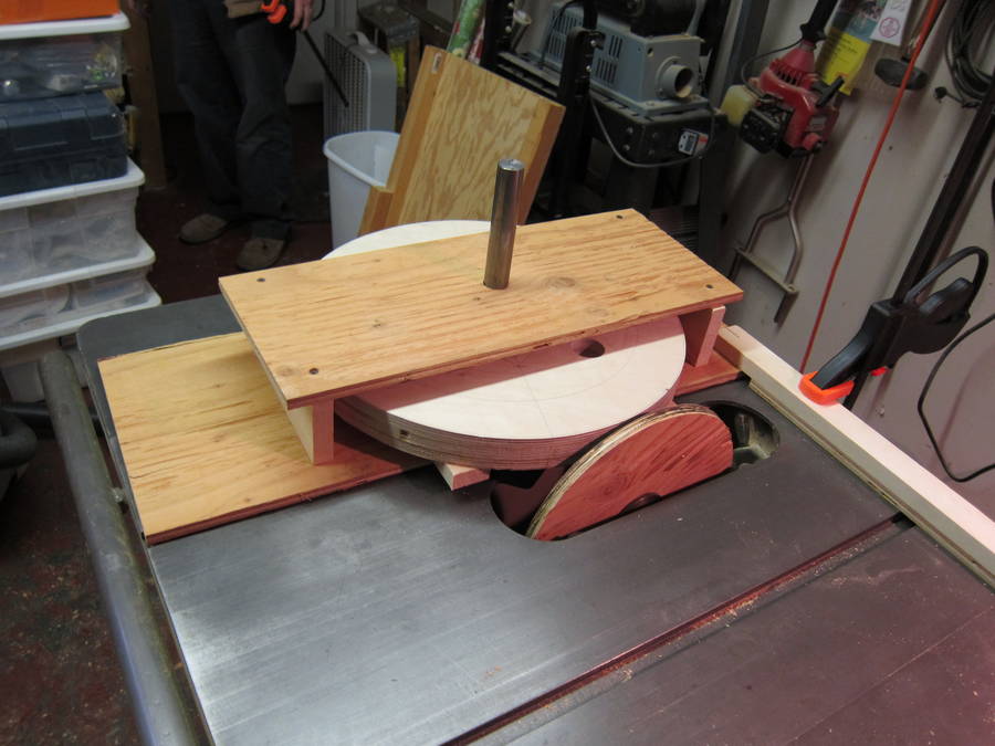 Next, we constructed a jig to house the wheel: just a
box with two open sides and 1" holes drilled in the top and bottom
(exactly placed one over the other) to house the shaft. The top was
fastened with screws, so it could easily be removed and replaced in the
exact same position. We installed a couple of wooden outrigger strips
to take up the distance from the hub of the bearing to the wheel
surface, so the wheel could rotate about its shaft exactly parallel to
the table. We attached a short strip to one corner of the jig with a
single screw. That way, when the strip was clamped to the edge of the
saw table, the jig can be swiveled into the sanding disc.
Next, we constructed a jig to house the wheel: just a
box with two open sides and 1" holes drilled in the top and bottom
(exactly placed one over the other) to house the shaft. The top was
fastened with screws, so it could easily be removed and replaced in the
exact same position. We installed a couple of wooden outrigger strips
to take up the distance from the hub of the bearing to the wheel
surface, so the wheel could rotate about its shaft exactly parallel to
the table. We attached a short strip to one corner of the jig with a
single screw. That way, when the strip was clamped to the edge of the
saw table, the jig can be swiveled into the sanding disc.
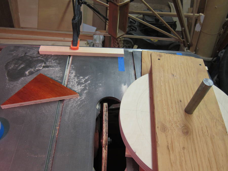 Marks on a
strip of tape on the opposite side of the table -- plus a clamped stop
block - then let us know exactly how far we had rotated it into the
disc. Then it was just a matter of rotating the wheel by hand while in
contact with the sanding disc. This made it easy to produce a flat edge
exactly 90 degrees to the face of the wheel -- and using our
registration marks and stop block, to ensure both wheels were turned to
exactly the same diameter. In addition, since the wheel rotates on its
shaft and bearings while being shaped, it ends up running true.
Marks on a
strip of tape on the opposite side of the table -- plus a clamped stop
block - then let us know exactly how far we had rotated it into the
disc. Then it was just a matter of rotating the wheel by hand while in
contact with the sanding disc. This made it easy to produce a flat edge
exactly 90 degrees to the face of the wheel -- and using our
registration marks and stop block, to ensure both wheels were turned to
exactly the same diameter. In addition, since the wheel rotates on its
shaft and bearings while being shaped, it ends up running true.
Matthias comments:
Looks like a good method. There is the possibility
that if you don't hold the wheel firmly enough, the sanding disk
might grab and spin it up to high speed!
 We used the same system to produce the crown on the wheels. Using the
tilt mechanism of the table saw, we'd first produce a 5 degree bevel on
one edge of one wheel (taking care not to go more than 1/5 of the way to
the center of the wheel) We then set our stop block for that angle, flip
the wheel over and run the same angle on the other edge. Then, without
changing the setting, we'd switch wheels and run the same thing on it.
So, flipping each wheel and switching back and forth while moving from 5
degrees through 1, we produced identical crowns on each wheel, and also
knew we had exactly the same amount of drop-off on either edge of each
wheel.
We used the same system to produce the crown on the wheels. Using the
tilt mechanism of the table saw, we'd first produce a 5 degree bevel on
one edge of one wheel (taking care not to go more than 1/5 of the way to
the center of the wheel) We then set our stop block for that angle, flip
the wheel over and run the same angle on the other edge. Then, without
changing the setting, we'd switch wheels and run the same thing on it.
So, flipping each wheel and switching back and forth while moving from 5
degrees through 1, we produced identical crowns on each wheel, and also
knew we had exactly the same amount of drop-off on either edge of each
wheel.
Matthias comments:
Most bandsaw wheels have a bit of a round or flat-ish
peak to the crown, just like yours. I prefer to make the crown with a slight
point to it -- the pointy crown really helps track the blade on center.
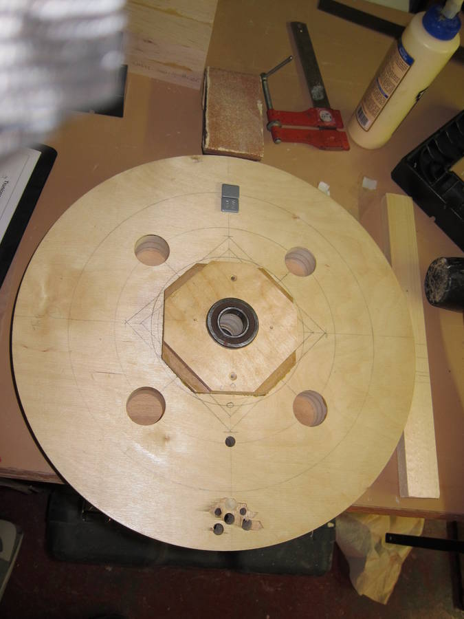 We had a bit of a struggle when it came time to balance the wheels. We
started by removing material from the wheels as the plans suggested, but
that wasn't working very well for us. Then I thought about my local tire
shop. They balance wheels all the time.
We had a bit of a struggle when it came time to balance the wheels. We
started by removing material from the wheels as the plans suggested, but
that wasn't working very well for us. Then I thought about my local tire
shop. They balance wheels all the time.
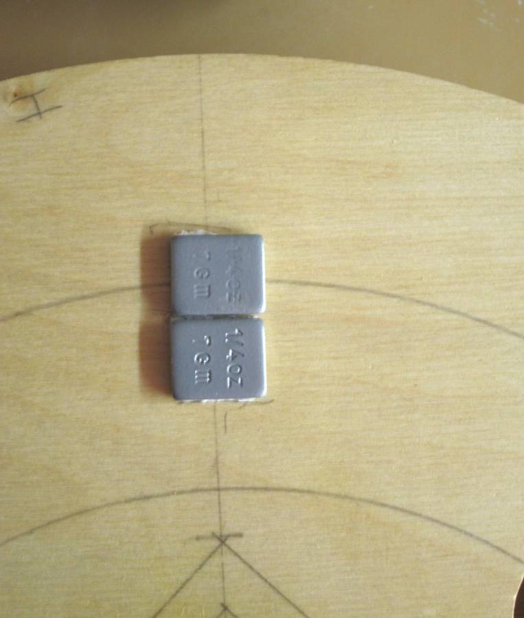 So I went down for a bit of
conversation and maybe some free advice, and came home with some wheel
balancing weights that the very helpful fellow there gave me (they come
in various sizes, but the ones we used were 7 grams each). After some
fiddling and cutting of the weights, this turned out to be just the
ticket. You just glue 'em on -- plus it's reversible if you start out
with a bit too much or a bit too little weight.
So I went down for a bit of
conversation and maybe some free advice, and came home with some wheel
balancing weights that the very helpful fellow there gave me (they come
in various sizes, but the ones we used were 7 grams each). After some
fiddling and cutting of the weights, this turned out to be just the
ticket. You just glue 'em on -- plus it's reversible if you start out
with a bit too much or a bit too little weight.
Matthias comments:
Funny, I actually use weights too in a way. I usually figure out
how large a piece of wood of similar density I need to add to balance,
then, instead of adding that wood to the light side, I drill out
a slightly lesser volume on the heavy side, then repeat.
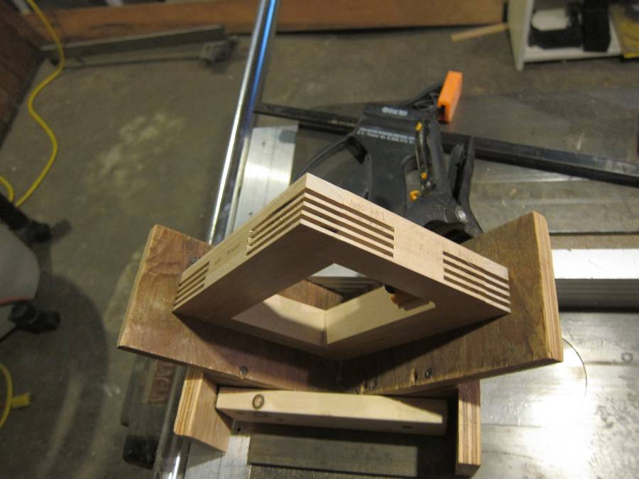
 We used a cradle jig and a key to register and cut the mitered slots
for the splines on the corners of the top wheel mount frame.
We used a cradle jig and a key to register and cut the mitered slots
for the splines on the corners of the top wheel mount frame.
 We decided to mount the motor to a secondary table. This allows us to
loosen the mounts and move the motor closer to the saw for installing
and/or tensioning the belt. We also have some adjustability if we have
to swap out the motor or decide we want to change the pulley size (our
pulleys are sized for a blade speed of about 3000 fps.) Don't know how
useful this will be, but it's there if we need it. Of course, we had to
change some of the dimensions of the saw frame
We decided to mount the motor to a secondary table. This allows us to
loosen the mounts and move the motor closer to the saw for installing
and/or tensioning the belt. We also have some adjustability if we have
to swap out the motor or decide we want to change the pulley size (our
pulleys are sized for a blade speed of about 3000 fps.) Don't know how
useful this will be, but it's there if we need it. Of course, we had to
change some of the dimensions of the saw frame
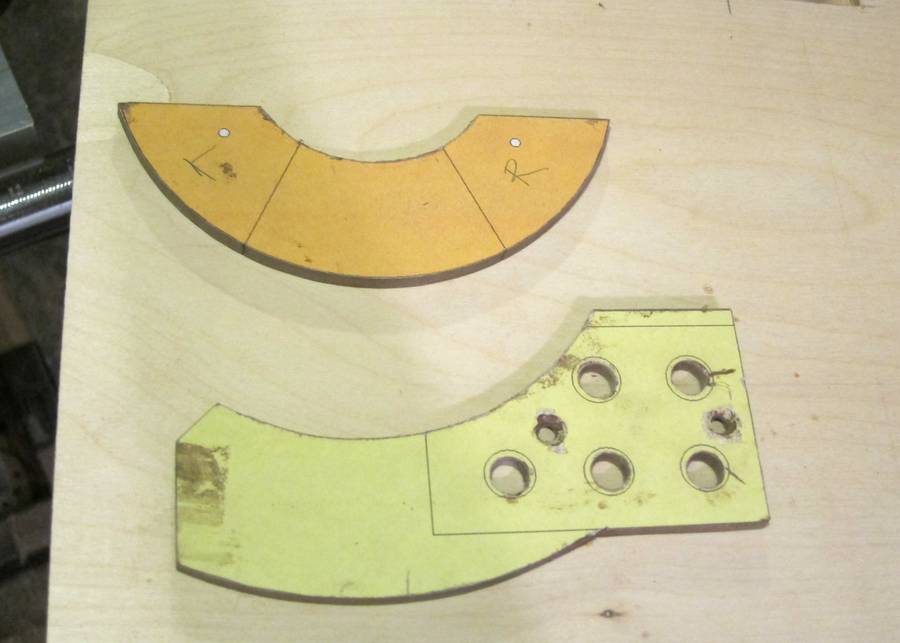 Since we didn't yet have a bandsaw when it came time to fabricate the
trunnion cradles and trunnion arches, we first made templates out of
1/4-inch hardboard scraps. We used spray adhesive to mount the 1:1 patterns
from our plans to the hardboard, then used a sabre saw and sanding
station to make sure they were really accurate and fit each other
perfectly.
Since we didn't yet have a bandsaw when it came time to fabricate the
trunnion cradles and trunnion arches, we first made templates out of
1/4-inch hardboard scraps. We used spray adhesive to mount the 1:1 patterns
from our plans to the hardboard, then used a sabre saw and sanding
station to make sure they were really accurate and fit each other
perfectly.
 We traced those templates onto our stock. We then used a
drill press and Forstner bit to get close to our line.
We traced those templates onto our stock. We then used a
drill press and Forstner bit to get close to our line.
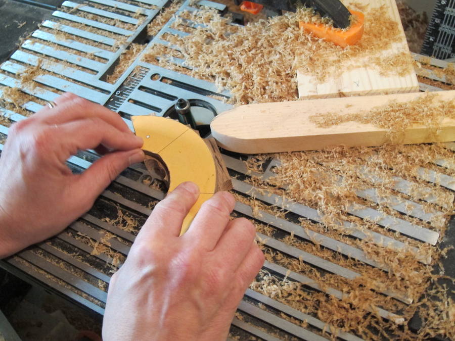 Mounting the
templates to the stock with double-stick tape, we used our router table
and a long flush-trim bit to pattern rout the cradles and arches (we
clamped a strip of wood with a rounded end to the table to act as a
starting pin.) The cradles and arches themselves were large enough to
handle safely, but we cut the partial arch segments for the center of
the arches sequentially out of a long piece of stock so we could keep
our hands a safe distance from the bit.
Mounting the
templates to the stock with double-stick tape, we used our router table
and a long flush-trim bit to pattern rout the cradles and arches (we
clamped a strip of wood with a rounded end to the table to act as a
starting pin.) The cradles and arches themselves were large enough to
handle safely, but we cut the partial arch segments for the center of
the arches sequentially out of a long piece of stock so we could keep
our hands a safe distance from the bit.
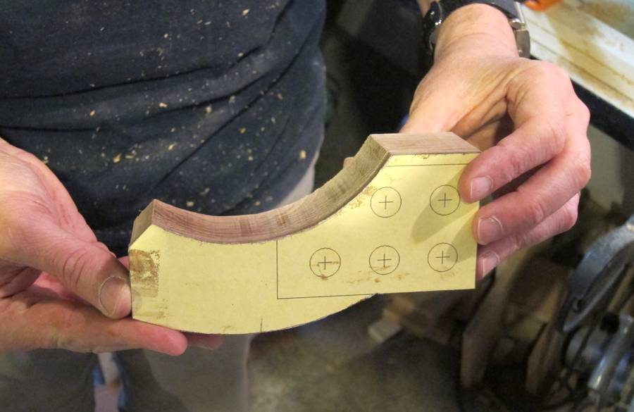 Pretty quick...
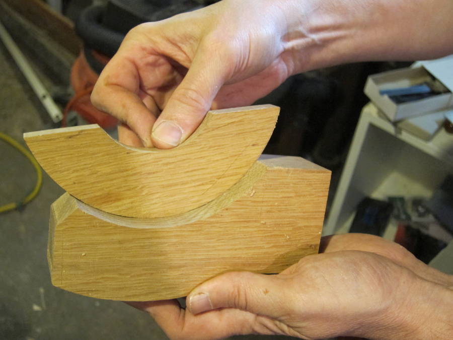 ... and resulted in a perfect fit.
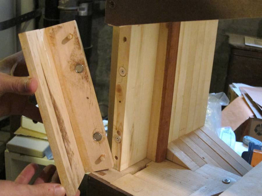 Rather than attach the left blade guard to the upper enclosure, we
installed rare earth magnets in the guard and washers in the frame, and
left it a separate piece. Short dowel pins register the guard and make
sure it's in the right place.
Rather than attach the left blade guard to the upper enclosure, we
installed rare earth magnets in the guard and washers in the frame, and
left it a separate piece. Short dowel pins register the guard and make
sure it's in the right place.
Matthias comments:
Yes, it is a bit tricky to put the top cover on and off with my design,
but I got used to it.
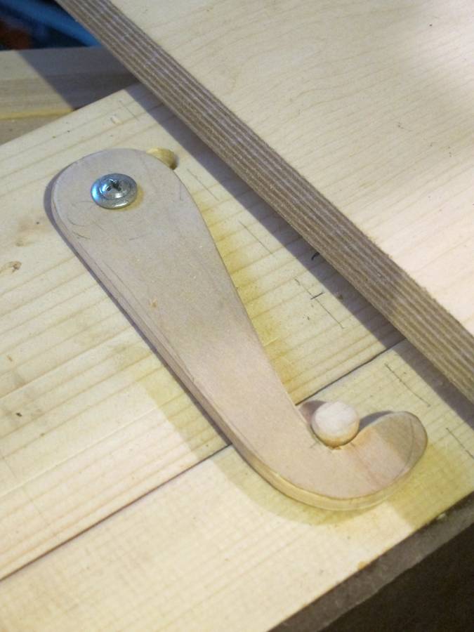 We also borrowed Gordon Millar's wooden hook idea.
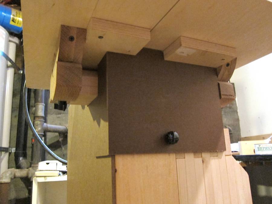 Finally, we liked the screw inserts from the trunnion support beam so
much, we installed one with a knob and stud to secure the blade guard
enclosure, instead of the toggle idea. We did later have to install a
leash so the knob doesn't get lost.
Finally, we liked the screw inserts from the trunnion support beam so
much, we installed one with a knob and stud to secure the blade guard
enclosure, instead of the toggle idea. We did later have to install a
leash so the knob doesn't get lost.
Matthias comments:
Never had that problem with my toggle design :)