 Having built the wheels and frame
for my new bandsaw, it was time to build the mounts for the wheels.
Having built the wheels and frame
for my new bandsaw, it was time to build the mounts for the wheels.
Having built the wheels and frame
for my new bandsaw, it was time to build the mounts for the wheels.
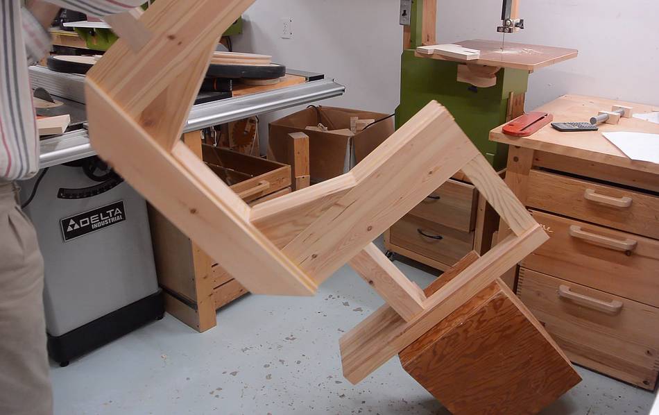
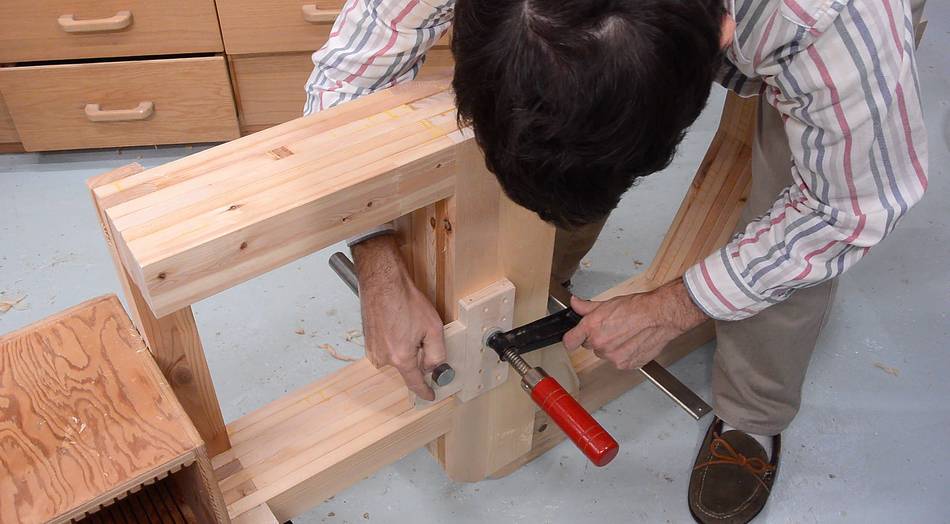
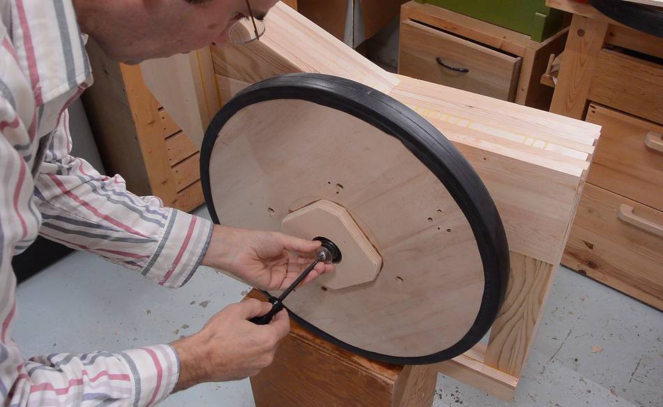
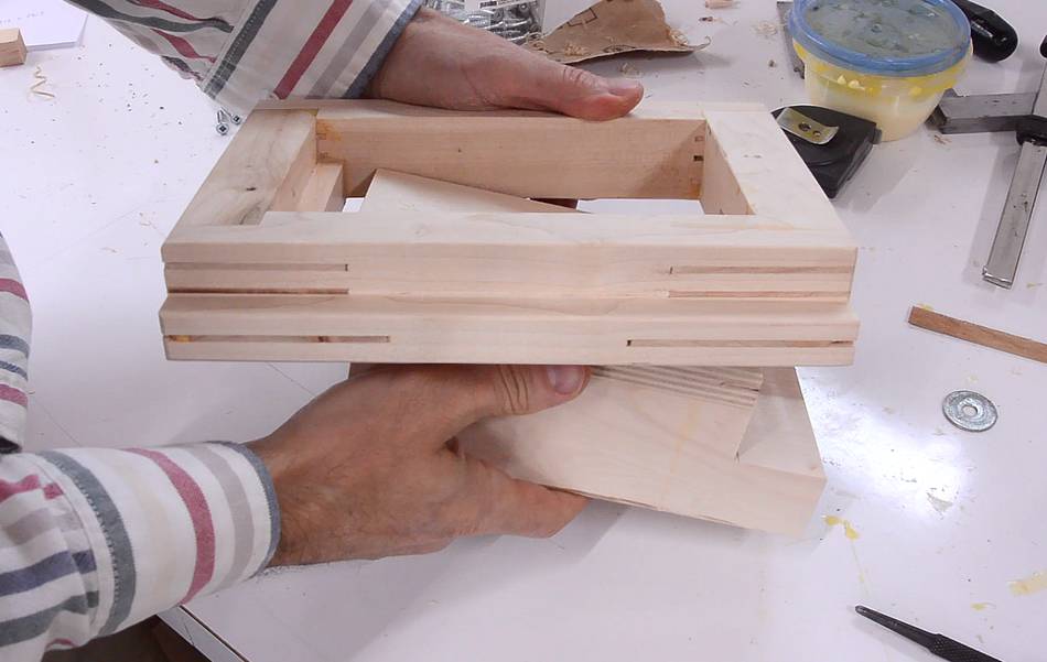
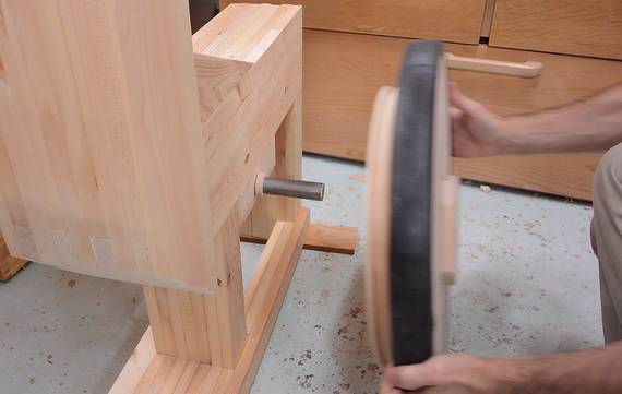
I tipped the frame on its side to make it easier to work on the lower wheel mount.

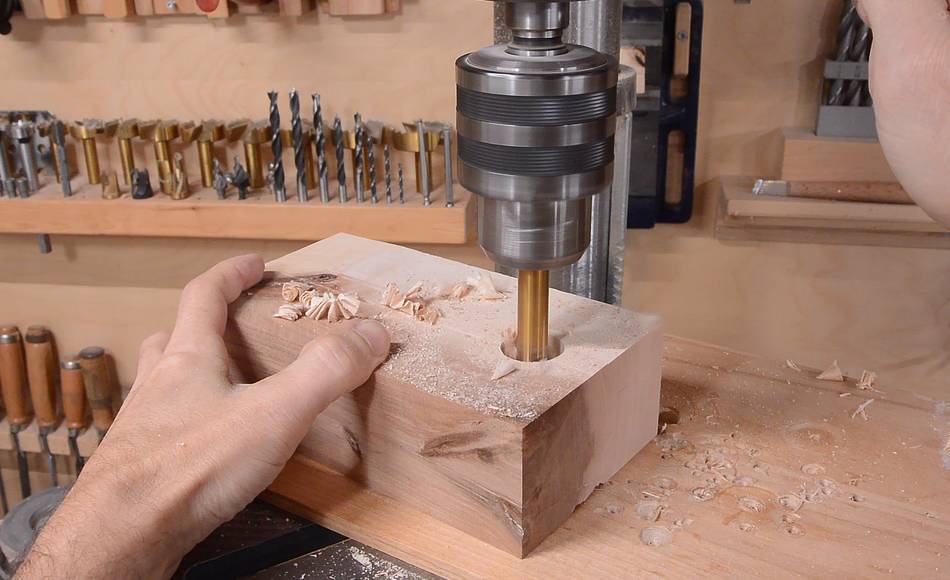
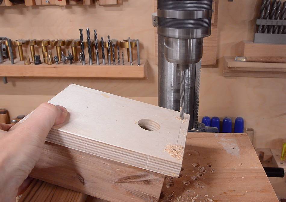
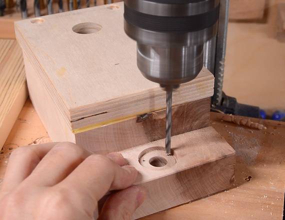
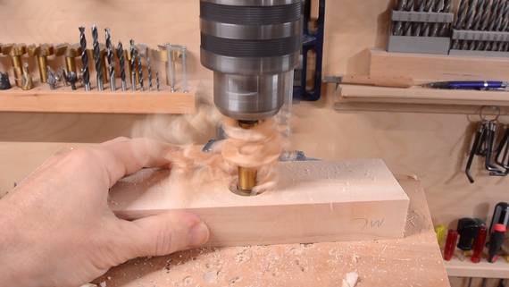 I drilled a 1" hole though a piece of hardwood, which will mount on the bottom
of the frame. At left, checking how it will fit.
I drilled a 1" hole though a piece of hardwood, which will mount on the bottom
of the frame. At left, checking how it will fit.
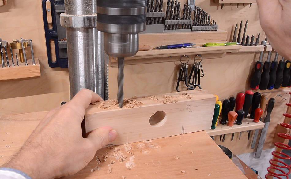
 Then drilling some holes for screws. The screw heads will be well below
the surface to accommodate the length of screws I had at hand.
The screws are just a bit longer than the block of wood is thick.
Then drilling some holes for screws. The screw heads will be well below
the surface to accommodate the length of screws I had at hand.
The screws are just a bit longer than the block of wood is thick.
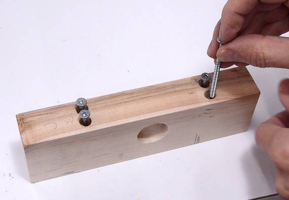
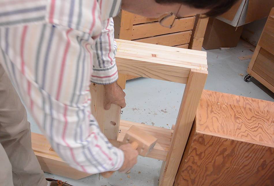 I placed the block where it needs to go and used a mallet to tap the screws
to leave divots in the wood.
I placed the block where it needs to go and used a mallet to tap the screws
to leave divots in the wood.
 The divots marked where to drill the pilot holes.
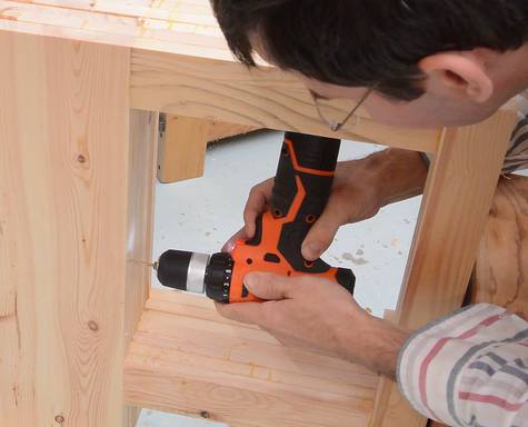
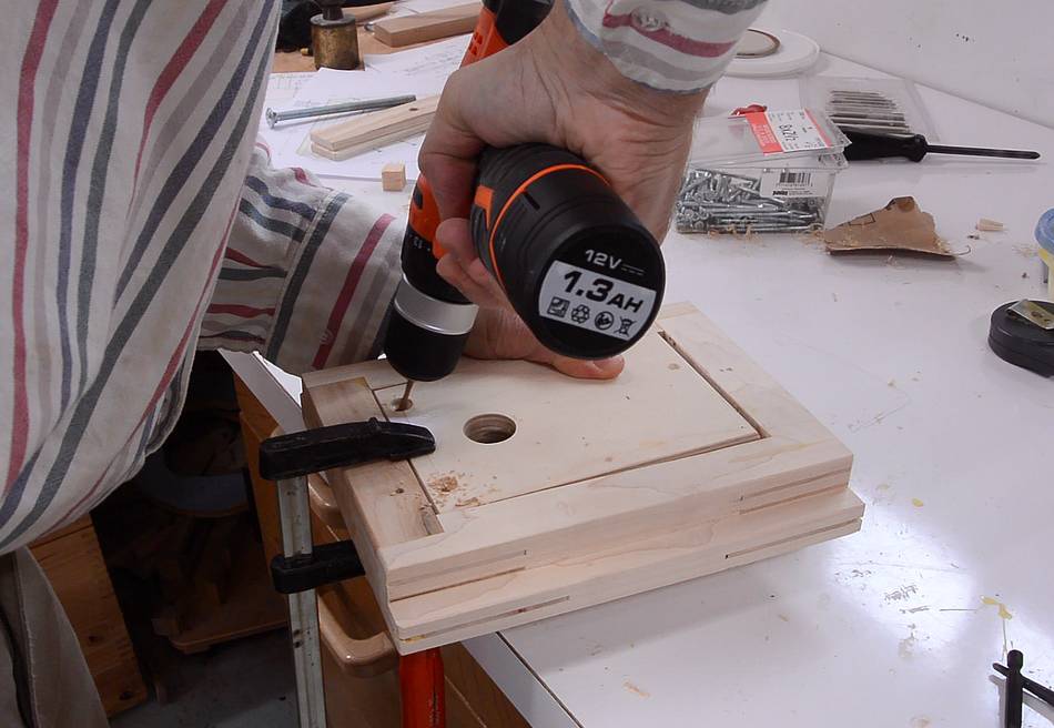
 Then screwing it on. The first drill I tried wouldn't fit in the space
under the frame, but this one had a body
short enough to fit, even though it's a bigger drill.
Then screwing it on. The first drill I tried wouldn't fit in the space
under the frame, but this one had a body
short enough to fit, even though it's a bigger drill.
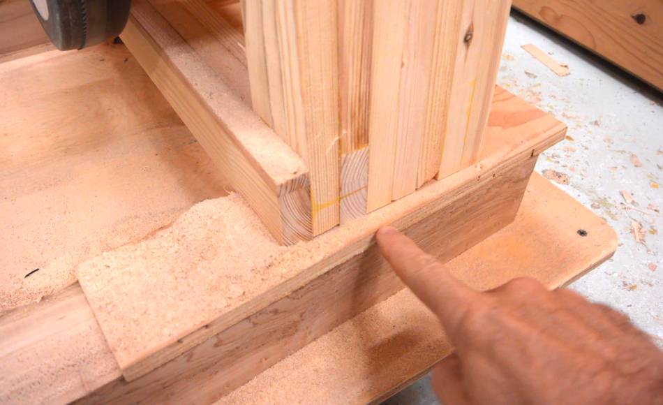
Blade tension will push the block up against the frame, while the drive belt will push it up against the leg. So the screws are there mostly to keep it from falling off when there's no blade on the saw.
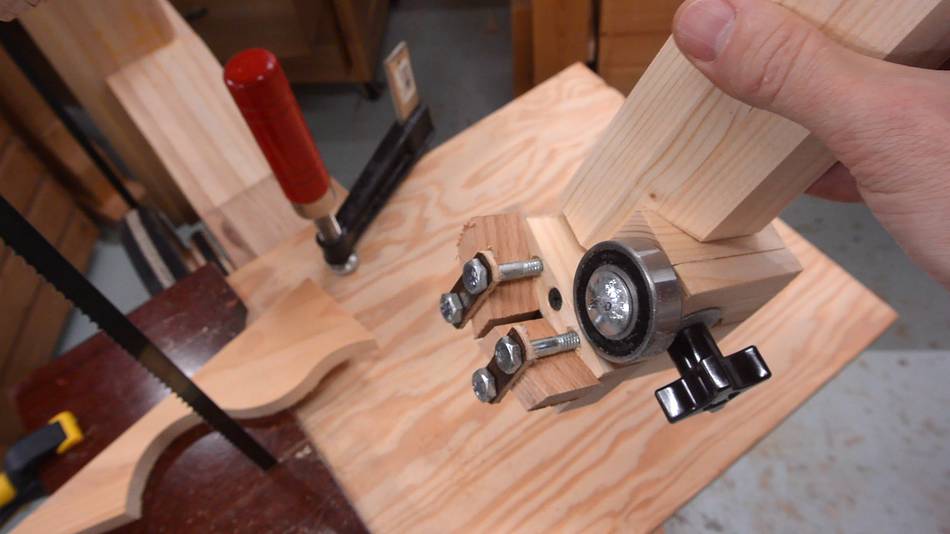
 Then I needed a holder for the back end of the shaft. This one is a bit
odd shaped because I just used a scrap of wood that used to be the old
tension/tracking adjust of my
homemade belt sander, but the shape
seemed very appropriate.
Then I needed a holder for the back end of the shaft. This one is a bit
odd shaped because I just used a scrap of wood that used to be the old
tension/tracking adjust of my
homemade belt sander, but the shape
seemed very appropriate.
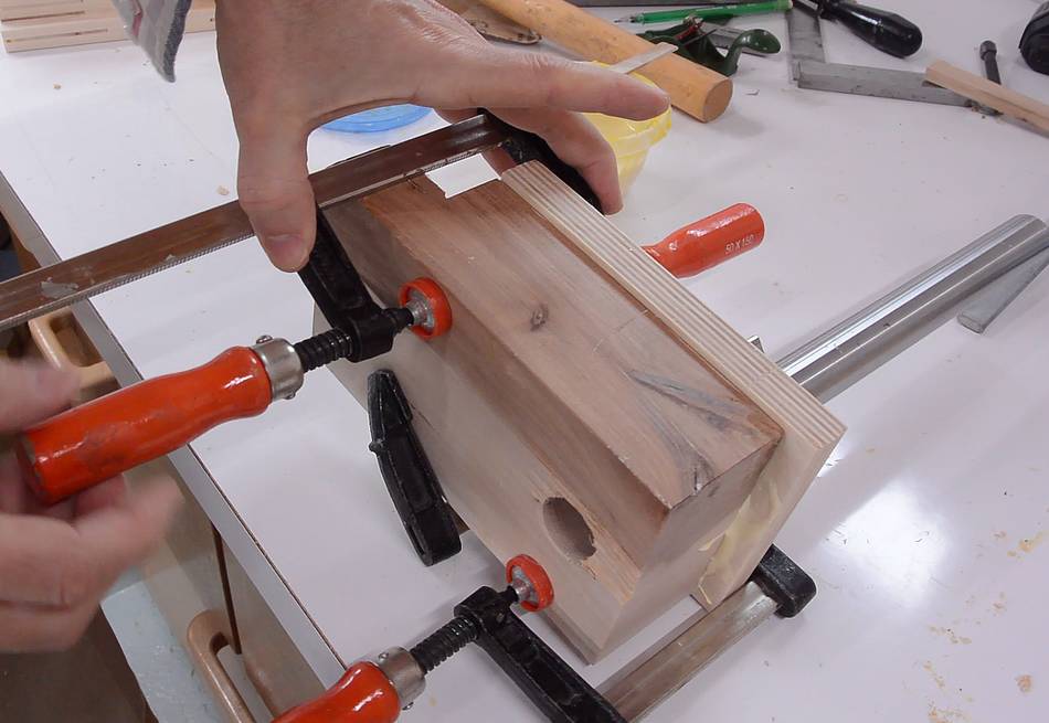
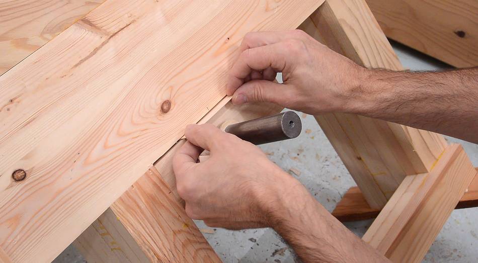
 Clamping it in place to check the fit.

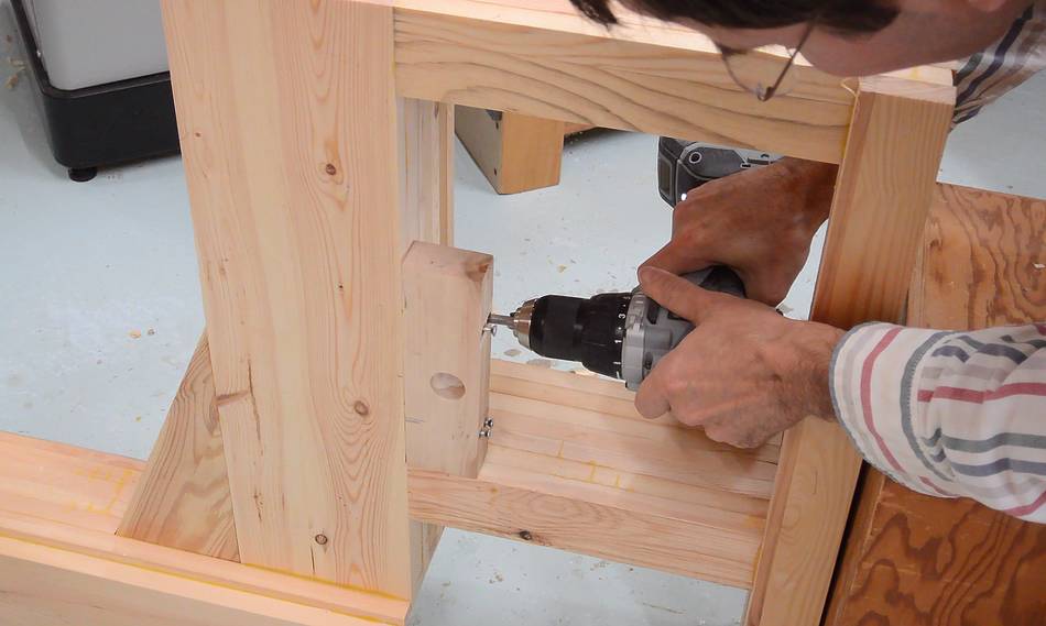
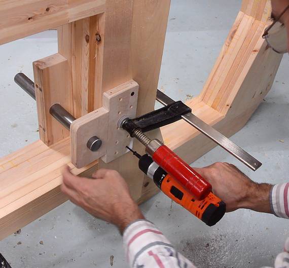 Then making sure the shaft is square to the frame before screwing it on.
For now, with just two screws. I plan on fully screwing and gluing this
on later.
Then making sure the shaft is square to the frame before screwing it on.
For now, with just two screws. I plan on fully screwing and gluing this
on later.
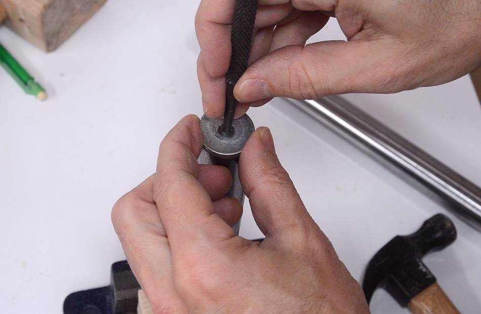 I need to mount a washer to the end of the shaft to keep the wheel from
sliding off. I start by punching a divot in the end of the shaft. I used
a 1" washer to help me place the center punch in the middle of the shaft before
hitting it with a hammer.
I need to mount a washer to the end of the shaft to keep the wheel from
sliding off. I start by punching a divot in the end of the shaft. I used
a 1" washer to help me place the center punch in the middle of the shaft before
hitting it with a hammer.
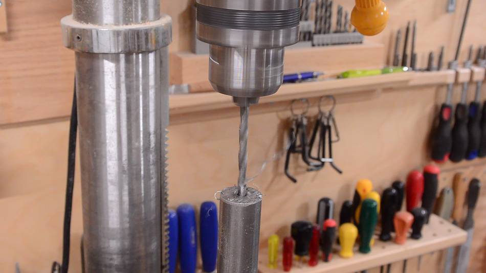 Then drilling the hole, about 20 mm deep, using a low speed on the drill press
and applying oil to the drill. The divot I punched earlier helps
to guide the drill in the right spot.
Then drilling the hole, about 20 mm deep, using a low speed on the drill press
and applying oil to the drill. The divot I punched earlier helps
to guide the drill in the right spot.
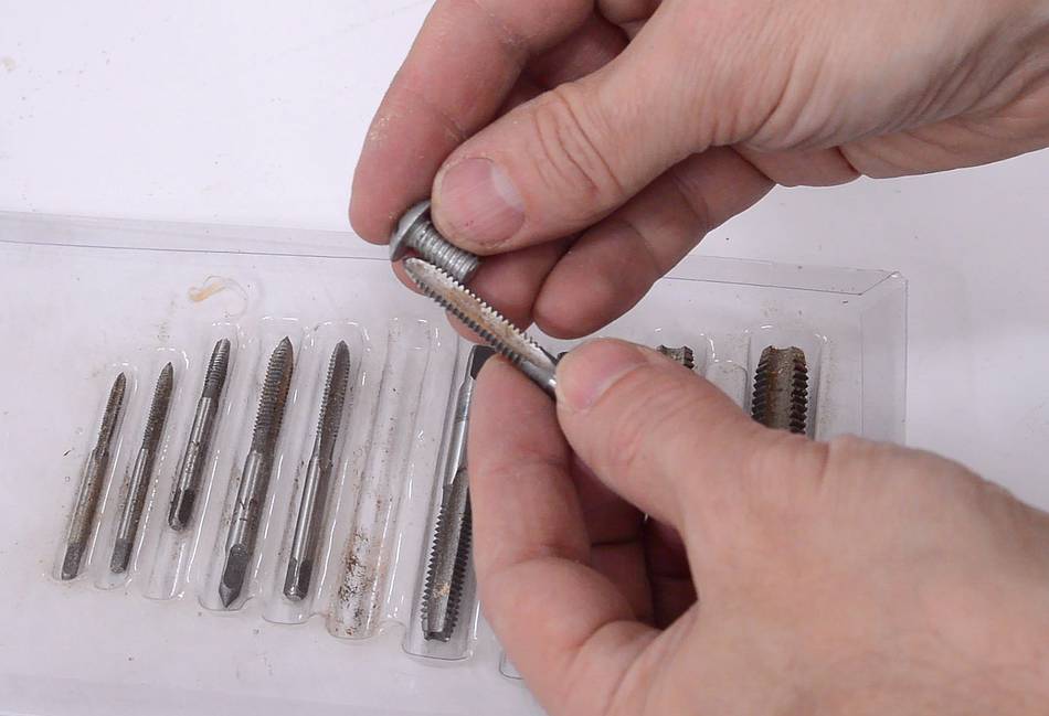
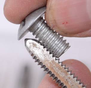 I have a pan-head screw with a relatively shallow head. Here checking which
tap matches that thread by holding the screw against the tap.
I have a pan-head screw with a relatively shallow head. Here checking which
tap matches that thread by holding the screw against the tap.
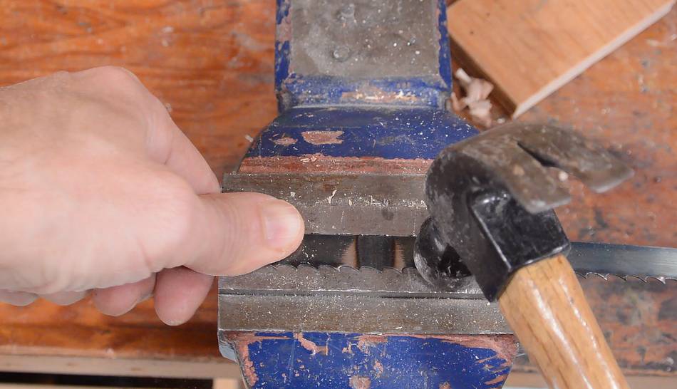
 Then tapping the hole. It's a 1/4" screw, and I drilled the hole at 7/32"
I put the shaft horizontally in the vise, then eyeballed the tap parallel to jaws of the vise to make sure I have it in straight.
 Then checking how the screw and washer fit.
 A small wooden spacer goes behind the lower wheel to keep it from rubbing
against the frame.
A small wooden spacer goes behind the lower wheel to keep it from rubbing
against the frame.
 Screwing on the washer to hold the wheel in place.
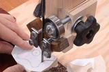
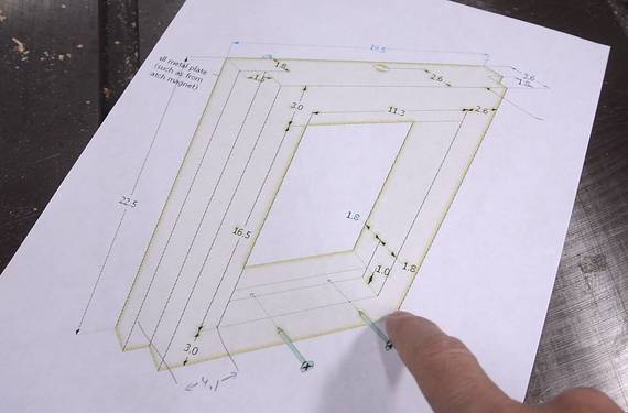 I made a printout of the upper wheel mount from my CAD model.
This template is also included in the
plans for this bandsaw
I made a printout of the upper wheel mount from my CAD model.
This template is also included in the
plans for this bandsaw
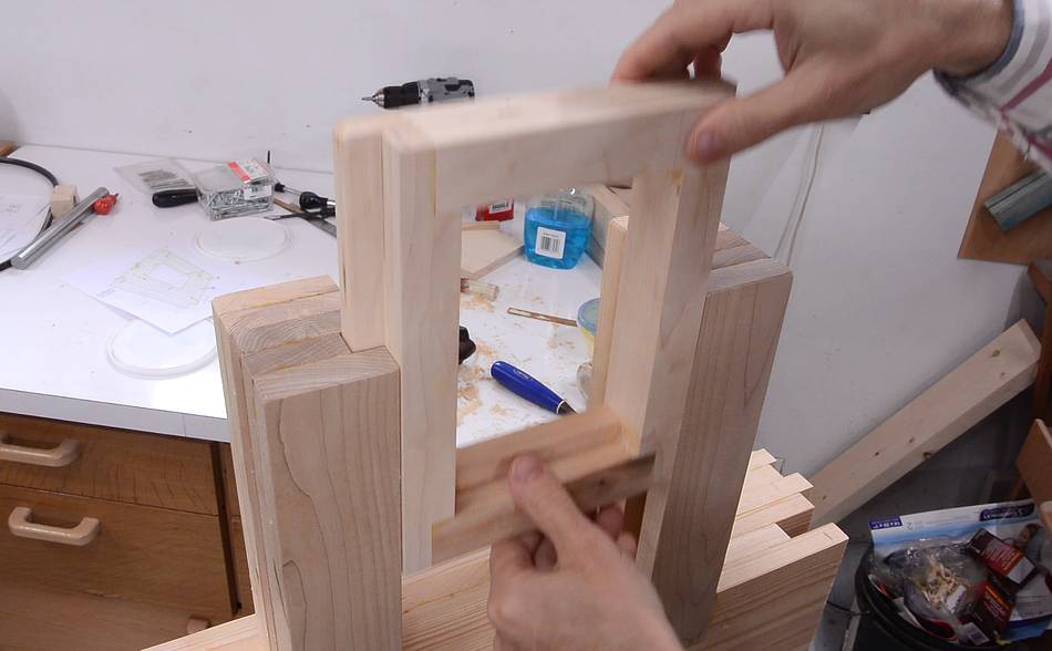
Ideally, the corners of this would be box joined. That's how I did it for my 16" bandsaw. But that would be difficult to do without a screw advance box joint jig (other styles of box joint jig aren't as suitable for cutting deep joints in hardwood). So I'll show another method - rabbet joined with splines.
 The rabbets were cut into the vertical pieces with two cuts on the
table saw each. Then gluing and clamping it together.
The rabbets were cut into the vertical pieces with two cuts on the
table saw each. Then gluing and clamping it together.
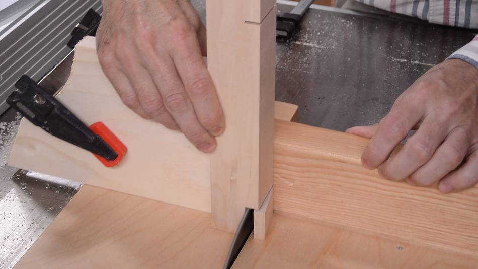
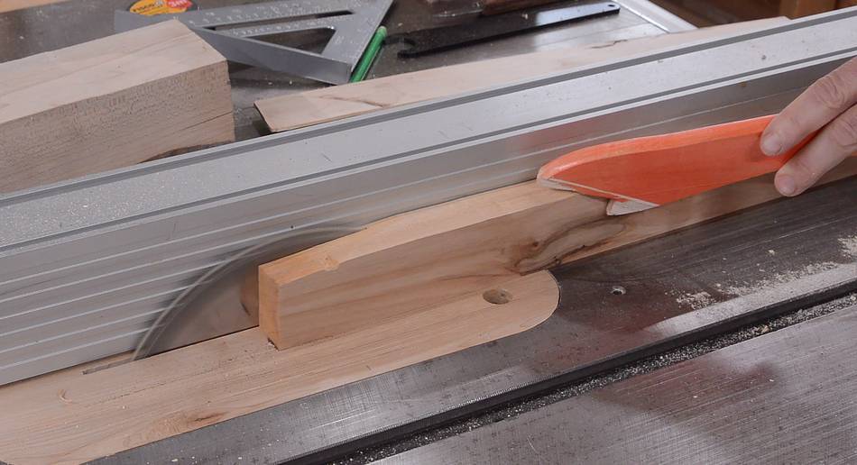
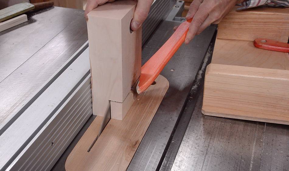
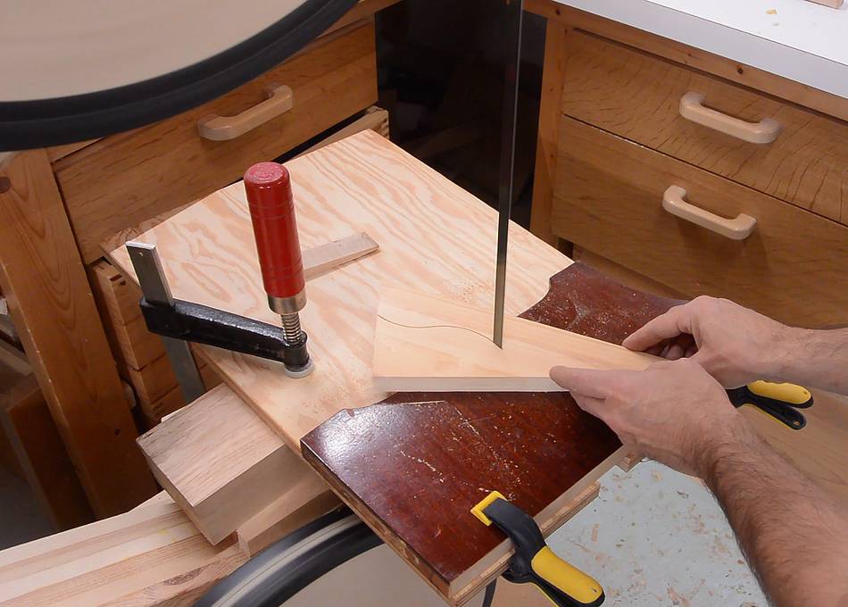
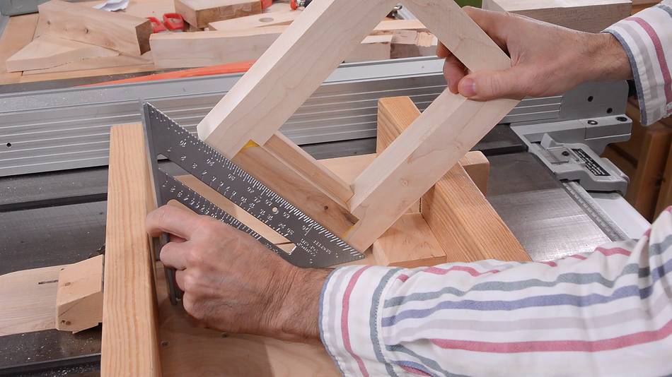 Once the glue was dry, it was time to cut the slots for the splines.
I used my table saw sled,
with a block of wood in it to hold the workpiece at 45°. I checked
that the angle was correct with a speed square.
Once the glue was dry, it was time to cut the slots for the splines.
I used my table saw sled,
with a block of wood in it to hold the workpiece at 45°. I checked
that the angle was correct with a speed square.
 Then clamping a larger block of wood on the far side of the jig to help
control the lateral position, and making a cut in each corner.
Then clamping a larger block of wood on the far side of the jig to help
control the lateral position, and making a cut in each corner.
I flipped the workpiece over and made another cut in each corner. I then repositioned the block to cut in the middle of each corner to bring the number of slots per corner up to three.
 I cut some thin strips of wood for the splines. I always cut this
between the blade and the fence, though you do need a zero clearance
insert for this sort of cut, or the just cut off piece will get sucked
into the table saw.
I cut some thin strips of wood for the splines. I always cut this
between the blade and the fence, though you do need a zero clearance
insert for this sort of cut, or the just cut off piece will get sucked
into the table saw.
It takes a few test cuts to get the thickness of the splines just right.
 Gluing in three splines into each corner.
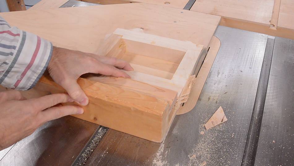 I cut the excess off on the table saw.
I used a narrow board as a spacer between the fence on the table saw sled and the workpiece for the first two cuts because the splines sticking out made it impossible to square the workpiece up directly against the sled's fence.
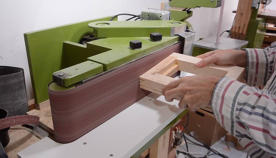 Then fully flushing it on the belt sander.
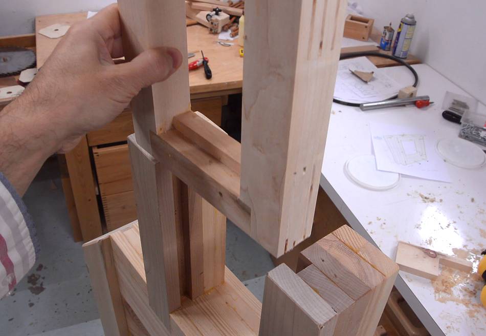 The frame needs to fit into the slots in the prongs at the
top of the frame. I need to cut a rabbet on either side of it for it to fit.
The frame needs to fit into the slots in the prongs at the
top of the frame. I need to cut a rabbet on either side of it for it to fit.
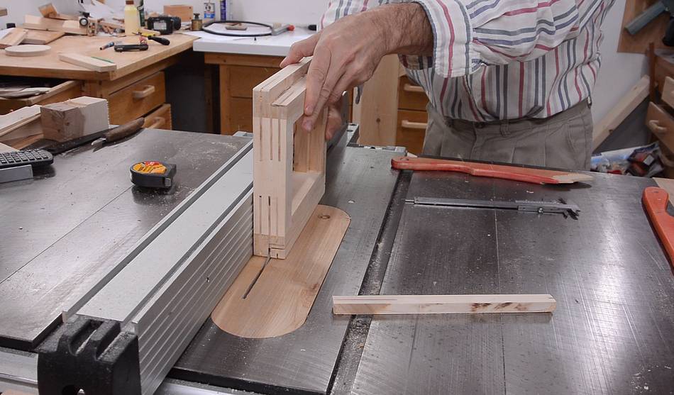 I cut this rabbet by making two cuts on the table saw.
 I didn't leave any margin, so it took a bit of tweaking and re-cutting
the rabbets progressively deeper to get a good fit.
I didn't leave any margin, so it took a bit of tweaking and re-cutting
the rabbets progressively deeper to get a good fit.
 The actual shaft (or axle) for the upper wheel gets mounted in a block
of wood, which can pivot in this frame. I'm making this block out of
two layers. The front is a piece of 18 mm Baltic birch plywood, with
a 1" hole in it.
The actual shaft (or axle) for the upper wheel gets mounted in a block
of wood, which can pivot in this frame. I'm making this block out of
two layers. The front is a piece of 18 mm Baltic birch plywood, with
a 1" hole in it.
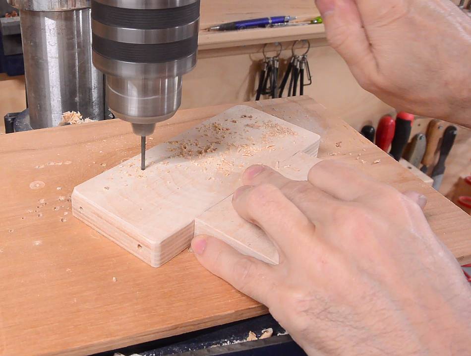
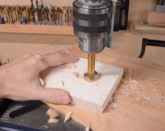
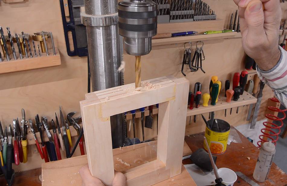
 A block of hardwood goes behind this, here drilling the hole in that.
As I drilled this hole, for every 1 cm of depth drilled I rotated the block 180 degrees about the vertical axis. When drilling big holes, a lot of force is involved, and the drill press table tends to flex downwards. So even if the table is perfectly square when you check it, it won't be while drilling. But by rotating the piece 180 degrees for every cm of depth, this angle error cancels out.
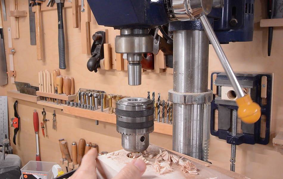 A slight oopsie. The drill press chuck came off! It's only
attached by friction. I cleaned the tapers and rammed it firmly on.
I guess I hadn't rammed it on hard enough the last time I had it off when
I checked if this chuck would fit
A slight oopsie. The drill press chuck came off! It's only
attached by friction. I cleaned the tapers and rammed it firmly on.
I guess I hadn't rammed it on hard enough the last time I had it off when
I checked if this chuck would fit
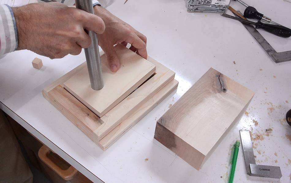
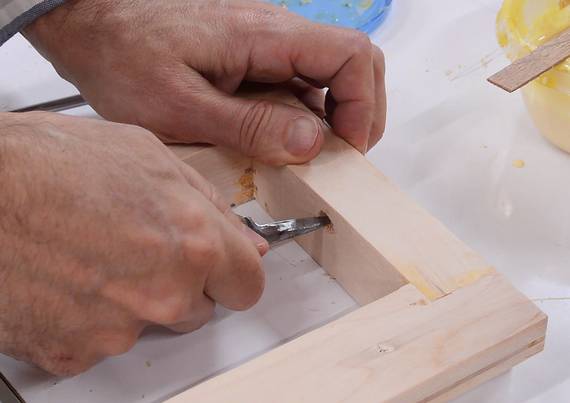
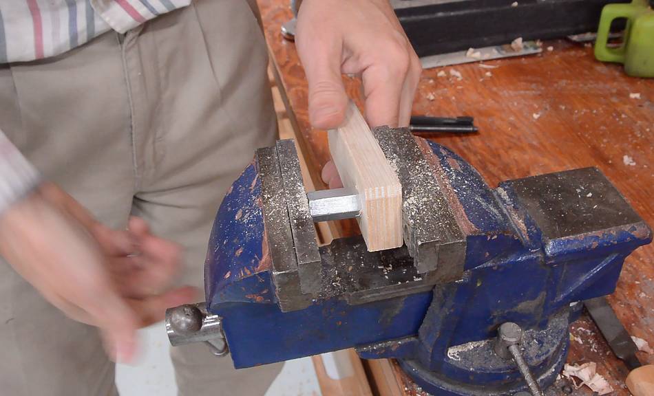
 The block also needs a rabbet cut out of it to make room for the tracking
adjust knob.
The block also needs a rabbet cut out of it to make room for the tracking
adjust knob.
 Finally, gluing the block onto the piece of plywood. I have the shaft
through the plywood and partway into the block to make sure the holes
line up as it's glued.
Finally, gluing the block onto the piece of plywood. I have the shaft
through the plywood and partway into the block to make sure the holes
line up as it's glued.
 I need some way to pull the upper wheel mount up to apply blade tension.
A carriage bolt through the upper wheel mount will serve that purpose.
I need some way to pull the upper wheel mount up to apply blade tension.
A carriage bolt through the upper wheel mount will serve that purpose.
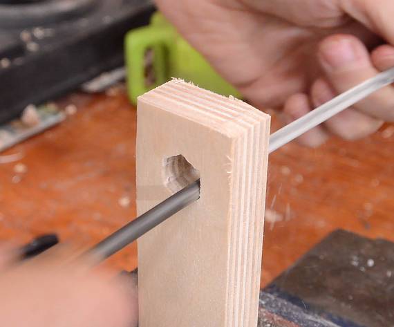
 After drilling the hole, I carved the end of it square with a
carving knife
After drilling the hole, I carved the end of it square with a
carving knife
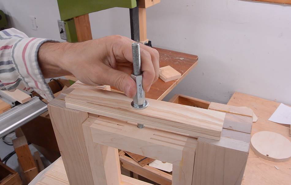 Some thin strips of wood across the top will act as a tension
spring, and a coupler nut on the carriage bolt will pull it up.
Some thin strips of wood across the top will act as a tension
spring, and a coupler nut on the carriage bolt will pull it up.
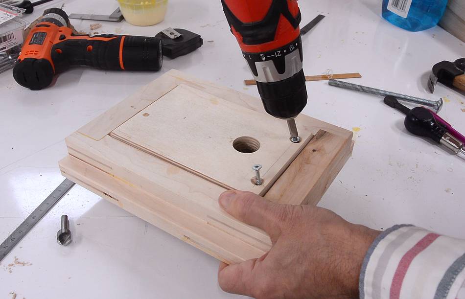
 With the glue on the block now dried, I can mount it in the frame.
It will get screwed to the edge on the bottom of the block.
With the glue on the block now dried, I can mount it in the frame.
It will get screwed to the edge on the bottom of the block.
 Drilling holes for the screws. The holes are a bit larger than
the screws will be.
Drilling holes for the screws. The holes are a bit larger than
the screws will be.
 Then drilling pilot holes for where the screws will go, through the hole
I just drilled. This makes getting the alignment right easier.
Then drilling pilot holes for where the screws will go, through the hole
I just drilled. This makes getting the alignment right easier.
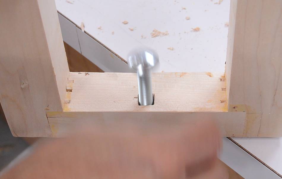
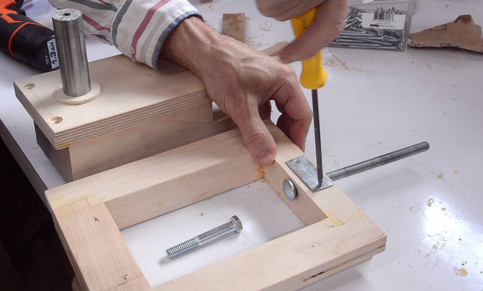
 But before mounting the block, I need to mount a T-nut in the block.
I didn't leave enough room for this, so I had to recess it in the block.
I think I'll change the dimensions in the plans to leave enough room
to make recessing the T-nut unnecessary.
But before mounting the block, I need to mount a T-nut in the block.
I didn't leave enough room for this, so I had to recess it in the block.
I think I'll change the dimensions in the plans to leave enough room
to make recessing the T-nut unnecessary.
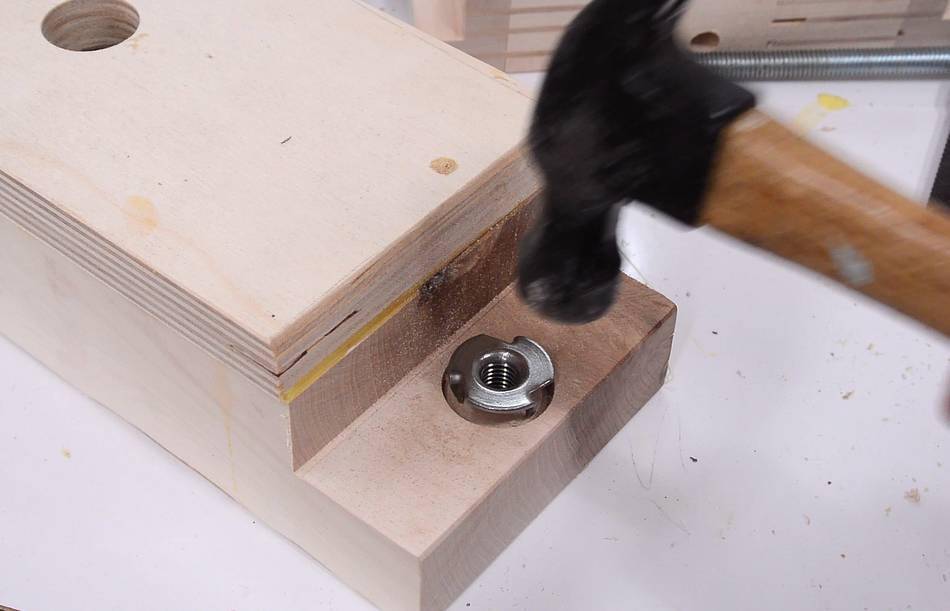
 Tapping the T-nut in place to mark where holes for the prongs need to go,
then drilling holes to fit the prongs.
Tapping the T-nut in place to mark where holes for the prongs need to go,
then drilling holes to fit the prongs.
 I then screwed the block into the frame.
I drilled the pilot holes in the plywood a bit large to leave the screws a little loose so it can pivot. Once blade tension is applied, the block is pushed down against the frame, and pulled back by the tracking adjust knob, so the screws are mostly there to keep it from falling out when there is no blade tension.
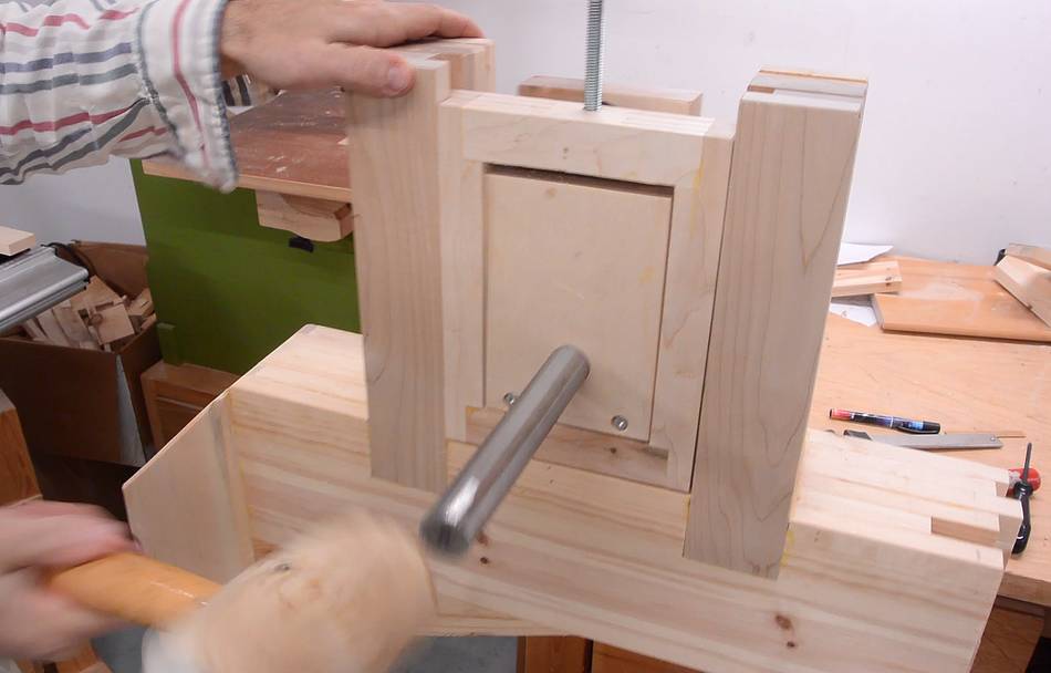 Inserting the shaft. This was a very tight fit. I think the hole in
the block of wood may have had a slight zigzag from my rotating the block
180 degrees every centimeter, but better zigzag than crooked.
It took a lot of pounding to get the shaft in.
Inserting the shaft. This was a very tight fit. I think the hole in
the block of wood may have had a slight zigzag from my rotating the block
180 degrees every centimeter, but better zigzag than crooked.
It took a lot of pounding to get the shaft in.
At least this way, I won't have to worry about keeping the shaft from sliding out.
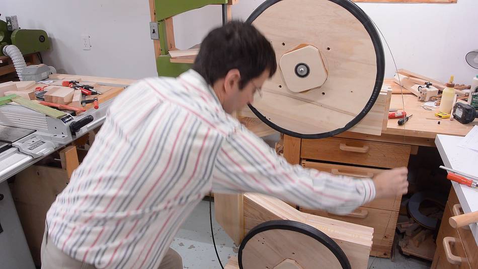 Putting the blade on for the first time. This is a 133" blade, though the
saw can also take 132" blades.
Putting the blade on for the first time. This is a 133" blade, though the
saw can also take 132" blades.
 Tensioned up and tracking adjusted.

 But checking alignment, it turned out the lower wheel was tilted up
very slightly. So I took the lower wheel off again...
But checking alignment, it turned out the lower wheel was tilted up
very slightly. So I took the lower wheel off again...
 ... and loosened the screws on the front block, and added some wooden veneer
shims (about 0.7 mm thick) between the block and the frame. That got it
aligned perfectly as far as I could tell.
... and loosened the screws on the front block, and added some wooden veneer
shims (about 0.7 mm thick) between the block and the frame. That got it
aligned perfectly as far as I could tell.
I also tried turning the wheels backwards to see if the blade would track differently. If it tracks differently spinning backwards, then the two wheel axles are not parallel.
Standing in front of the bandsaw, if spinning it backwards (counter clockwise) makes the blade wander away from you, then the top wheels would be turned towards the right. To fix it, the "right side" of the wheel needs to be further away (it would need to yaw to the left, to use aircraft terminology).
 Clamping on the same little 1/3 hp utility motor I used earlier to test
it under power.
Clamping on the same little 1/3 hp utility motor I used earlier to test
it under power.
It worked fine, but I could see the blade moving forwards and back as it went around. This happened at the same rate as the blade went round and around, so I knew it was the blade, not the wheels, causing this. This is typically caused by a misaligned weld.
 I have "fixed" this type of weld before by hammering the blade. Hammering
the blade expands the metal. So if I hammer near the teeth, that will cause the
tooth side to become "convex" so to say.
I have "fixed" this type of weld before by hammering the blade. Hammering
the blade expands the metal. So if I hammer near the teeth, that will cause the
tooth side to become "convex" so to say.
I have to say though, checking it with a ruler, I got it the wrong way around, so first I thought I had to hammer near the teeth. This made it worse, so I hammered it near the back edge. It wasn't perfect after that, but much better than before.
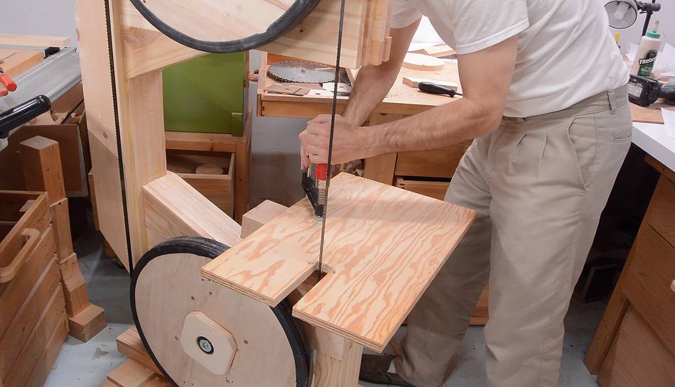 Incomplete as the saw was, I was keen to try to make some cuts with it.
So I clamped a temporary table to the frame (with some blocks of wood to
get it to the right height)
Incomplete as the saw was, I was keen to try to make some cuts with it.
So I clamped a temporary table to the frame (with some blocks of wood to
get it to the right height)
 An important safety tip, before trying it out, is to screw some boards to the
bottom of the frame. Without these the frame is a bit "tippy" and there is
the risk that the saw might tip onto you.
An important safety tip, before trying it out, is to screw some boards to the
bottom of the frame. Without these the frame is a bit "tippy" and there is
the risk that the saw might tip onto you.

 I also cut some curves in a piece of wood. I didn't get a narrow blade, but it looks
like this blade can cut a tight enough radius for the trunnions for this saw, which
I will be cutting on this incomplete saw later.
I also cut some curves in a piece of wood. I didn't get a narrow blade, but it looks
like this blade can cut a tight enough radius for the trunnions for this saw, which
I will be cutting on this incomplete saw later.
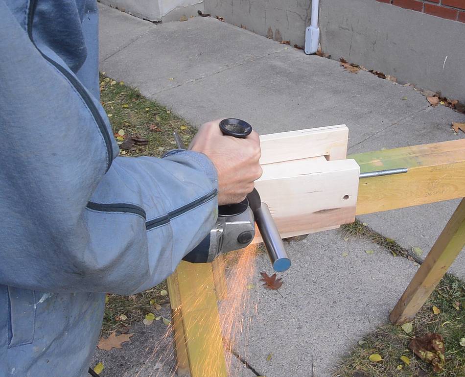 I still needed to trim the top shaft to its final length. I bought the shafts
as cut-offs at the Metal Supermarket, so they were longer than I needed.
I still needed to trim the top shaft to its final length. I bought the shafts
as cut-offs at the Metal Supermarket, so they were longer than I needed.
With the shaft as tight in the block as it was, I figured it was easier to cut it off while clamped in place. I'm cutting it off with a thin cut-off disk in the angle grinder. More on cutting metal with an angle grinder here
 I also made a small metal plate to screw to the top of the frame.
This keeps the tracking adjust screw from digging into the wood.
I also made a small metal plate to screw to the top of the frame.
This keeps the tracking adjust screw from digging into the wood.
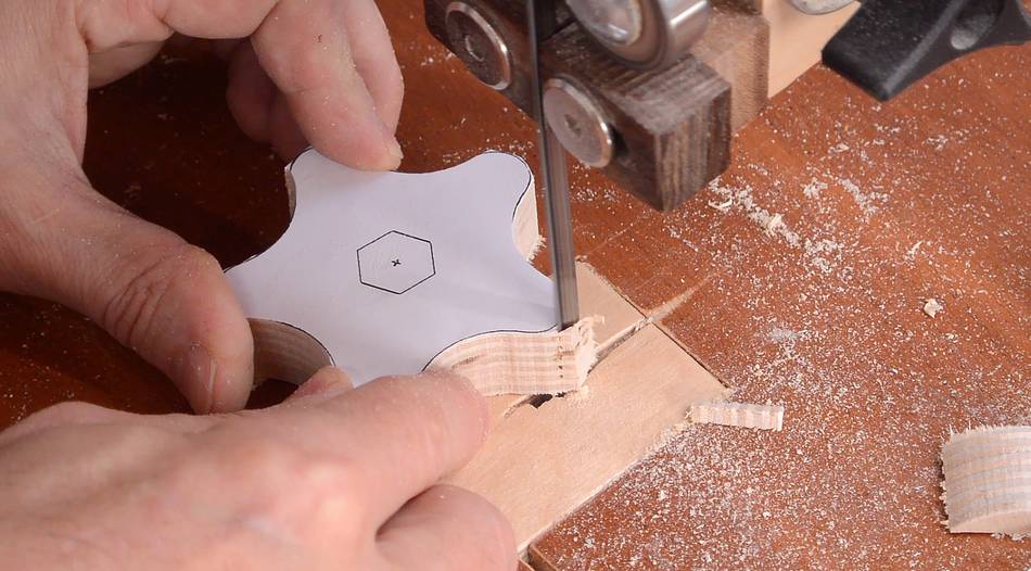
 I made a nice star knob for the tracking adjust, using my bandsaw.
The knob has a hexagonal hole chiselled in the back, which fits around
the head of the bolt.
I made a nice star knob for the tracking adjust, using my bandsaw.
The knob has a hexagonal hole chiselled in the back, which fits around
the head of the bolt.
I wasn't thinking when I made this - if you are building a bandsaw, it's not unlikely that you don't already have a bandsaw. So you can either make this a straight bar knob (no bandsaw needed), or wait until the rest of your bandsaw is done and then make this knob.
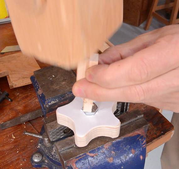
 New tracking knob installed. Note how the bolt pushes against the metal plate
installed earlier.
New tracking knob installed. Note how the bolt pushes against the metal plate
installed earlier.
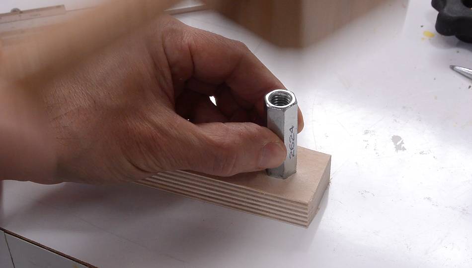
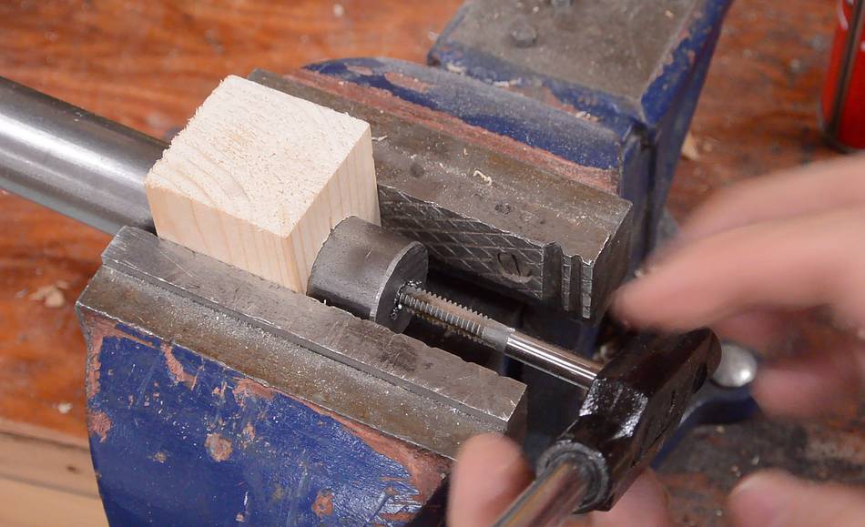
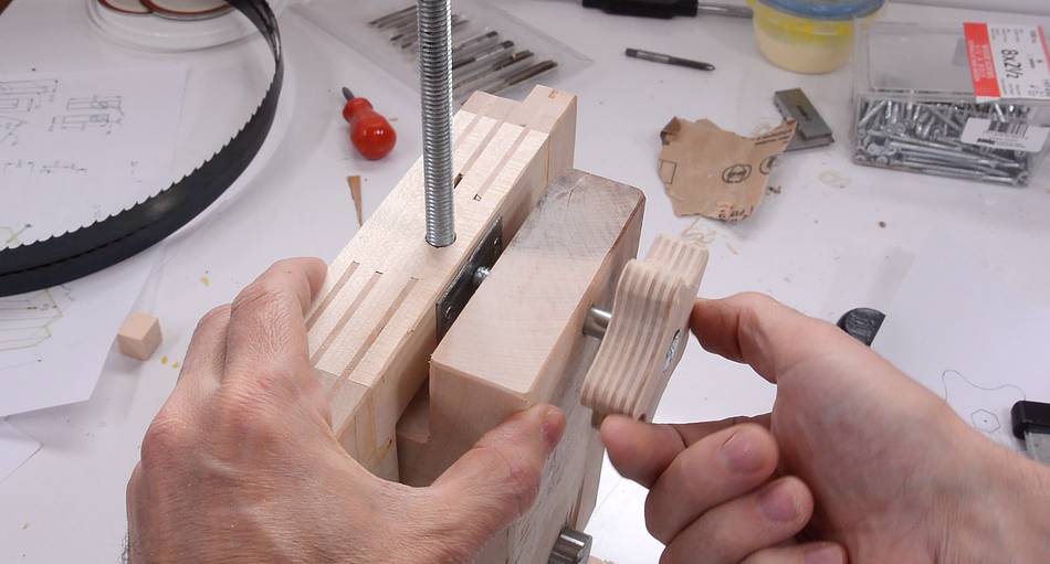
 I made a crank for adjusting the tension by drilling a hole just slightly smaller
than a coupler nut, then pounding the coupler nut onto the (too small) hole to leave
six dents where the points of the nut are. I then filed these out a bit to make
a better fit for the nut...
I made a crank for adjusting the tension by drilling a hole just slightly smaller
than a coupler nut, then pounding the coupler nut onto the (too small) hole to leave
six dents where the points of the nut are. I then filed these out a bit to make
a better fit for the nut...
 ... then pressed the nut into the hole in a vise.
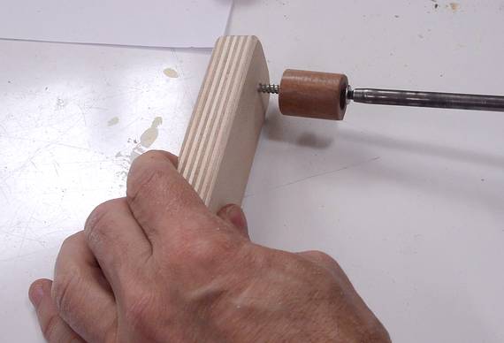 A small piece of dowel screwed onto the other end of the piece of plywood forms
a crank.
A small piece of dowel screwed onto the other end of the piece of plywood forms
a crank.
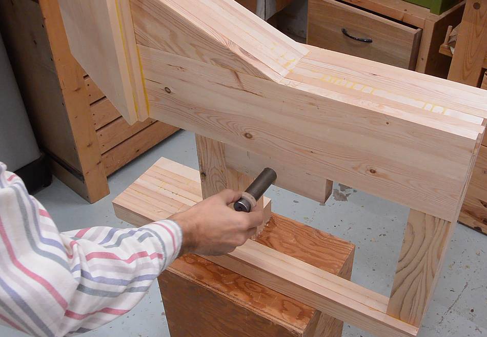
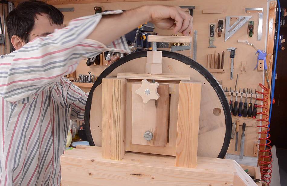 Installing the crank on the saw. Note the two blocks to bring the crank up high
enough to clear the top of the wheel.
Installing the crank on the saw. Note the two blocks to bring the crank up high
enough to clear the top of the wheel.
 With the top wheel mount done, I finished up the bottom one by taking the back block
off, adding glue, then adding ten screws to fix it firmly in place.
With the top wheel mount done, I finished up the bottom one by taking the back block
off, adding glue, then adding ten screws to fix it firmly in place.
I also added a screw and washer to the back of the shaft to keep it from sliding forward. This shaft was a bit longer than I needed, but to save the trouble of cutting it to length, I put a spacer on the end of the shaft instead.
I would have done the same for the back of the top wheel shaft, but that shaft is in the block so tight, I figured this was unnecessary.
 The next step was to make some blade guides for this saw.
I made a sort of mock-up (out of scrap wood) to see how my new design would look.
I came up with a slightly different design to accommodate wider blades than my
previous bandsaws.
The next step was to make some blade guides for this saw.
I made a sort of mock-up (out of scrap wood) to see how my new design would look.
I came up with a slightly different design to accommodate wider blades than my
previous bandsaws.
Next: Blade guides
 Blade guides
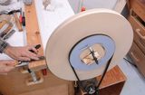 Making the bandsaw wheels
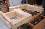 Making the frame
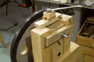 Wheel mounts for
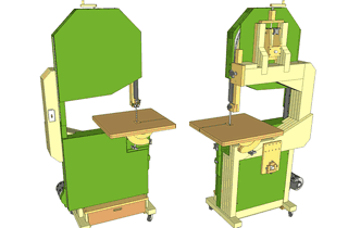 Buy the plans for this bandsaw