More photos of the computerized table saw jig
I had originally written my article about my computer controlled table saw jig back in 2003. Back then, bandwidth was not cheap. so in 2009, I also made a video about it.
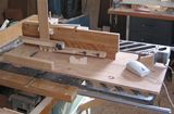
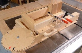
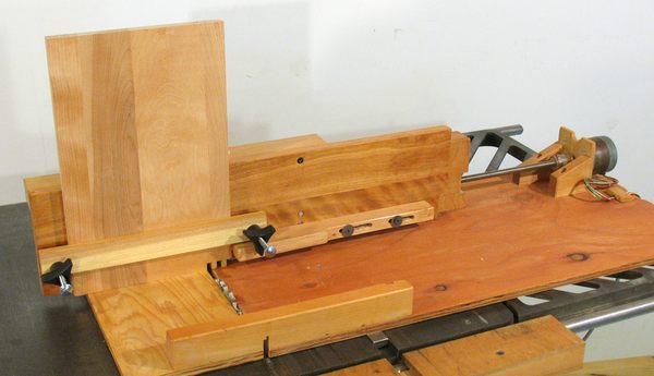 This is the jig set up for cutting box joints. Multiple boards can be clamped
onto the jig, but it's not as sturdy as my screw advance
box joint jig, nor is the motor powerful enough to move a large stack of boards.
This is the jig set up for cutting box joints. Multiple boards can be clamped
onto the jig, but it's not as sturdy as my screw advance
box joint jig, nor is the motor powerful enough to move a large stack of boards.
There's a piece of wood held down with a knob on either side of the board
to hold the board in place. Also, to the right of the board is an adjustable
"stop" which serves as a reference for making repeatable cuts.
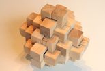
 One of the things that the jig is really good at is cutting burr puzzles.
I wrote a program on my computer that knows all the cut positions for the puzzle
pieces and sequences through them automatically.
One of the things that the jig is really good at is cutting burr puzzles.
I wrote a program on my computer that knows all the cut positions for the puzzle
pieces and sequences through them automatically.
The puzzle pieces require cuts from two sides, so after the cuts from one side are made, the motor returns to the 'home' position, and piece is removed, turned 90 degrees, and mounted again.
The reference stop on the right side, which the piece is always slid up against
ensures that the lateral positions of the cuts from either side are consistent.
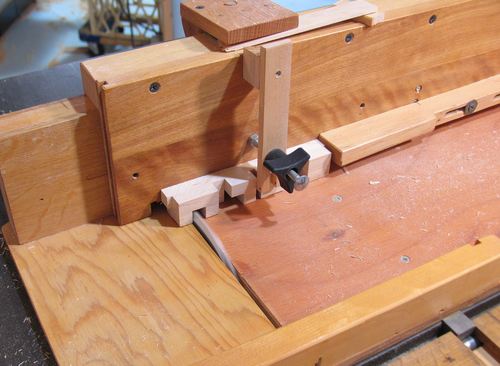
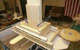
 The work piece is always clamped to the board on the front of the jig. This board
slides against a thicker stationary board. Inside the thicker board is a hollowed
out section where a nut on a threaded rod pulls the front board back and forth.
The work piece is always clamped to the board on the front of the jig. This board
slides against a thicker stationary board. Inside the thicker board is a hollowed
out section where a nut on a threaded rod pulls the front board back and forth.
To keep the board pushed up against the stationary board, a ball bearing,
mounted to the moving part, pulls the sliding board back against the stationary board.
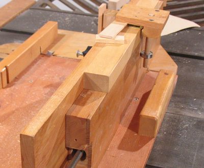
 This shot shows the slot in the stationary board. A block of wood with a T-nut
attached to it slides in the slot. The sliding board that the work pieces get
clamped to has two screws that screw into the sliding block with the T-nut.
This shot shows the slot in the stationary board. A block of wood with a T-nut
attached to it slides in the slot. The sliding board that the work pieces get
clamped to has two screws that screw into the sliding block with the T-nut.
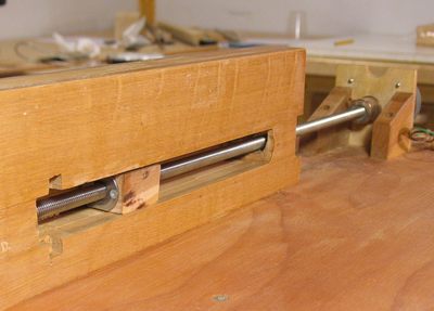
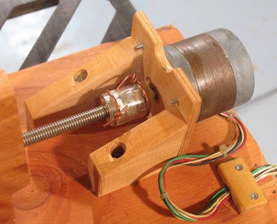 A 3/8" threaded rod is turned by a stepper motor. The coupling between the
1/4" stepper motor shaft and the threaded rod is a bit of a kluge. A nut that
can clamp onto a 1/4" shaft is mounted to the motor's shaft, and two 3/8" nuts
are jammed against each other on the threaded rod. The two parts are tied together
with a piece of stiff clear plastic tubing.
A 3/8" threaded rod is turned by a stepper motor. The coupling between the
1/4" stepper motor shaft and the threaded rod is a bit of a kluge. A nut that
can clamp onto a 1/4" shaft is mounted to the motor's shaft, and two 3/8" nuts
are jammed against each other on the threaded rod. The two parts are tied together
with a piece of stiff clear plastic tubing.
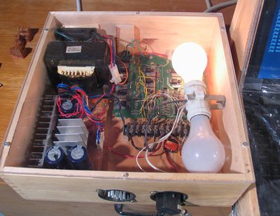 Here's a photo of the motor driver circuitry.
on the left is the DC power supply. It came from some printer or something (I don't remember)
and supplies about 40 volts. The transistor board is on the right side.
It has lots of fly wires on it, as I modified an existing circuit board for my purposes.
I really don't know what the circuit board was for, but it had good size transistors on
it and was wired in a topology close to what I needed, so I re-purposed the board to be a
stepper motor driver.
Here's a photo of the motor driver circuitry.
on the left is the DC power supply. It came from some printer or something (I don't remember)
and supplies about 40 volts. The transistor board is on the right side.
It has lots of fly wires on it, as I modified an existing circuit board for my purposes.
I really don't know what the circuit board was for, but it had good size transistors on
it and was wired in a topology close to what I needed, so I re-purposed the board to be a
stepper motor driver.
Without fancy current limiting PWM choppers, current limiting resistors are required for stepper
motor drivers. These can be quite expensive, but 100 watt light bulbs turned out to be
about right, so I just used light bulbs. It's nice to see the bulbs light up in different
ways as the jig is used.
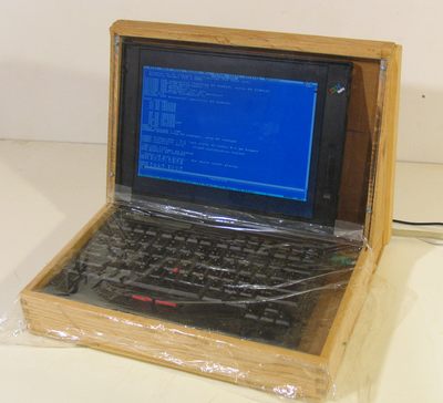 The jig is controlled by a 1996 vintage ThinkPad laptop computer, with a Pentium 133.
I'm running quick basic on it under DOS.
That way, I can do all the sub-millisecond step timings with
simple delay loops, and the operating system doesn't get in the way or interrupt much.
It's primitive, but it works.
The jig is controlled by a 1996 vintage ThinkPad laptop computer, with a Pentium 133.
I'm running quick basic on it under DOS.
That way, I can do all the sub-millisecond step timings with
simple delay loops, and the operating system doesn't get in the way or interrupt much.
It's primitive, but it works.
I made a wooden dust proof enclosure for the laptop computer. The screen is behind Plexiglass, but the keyboard is only covered with saran wrap, so I can still type on it.
The computer doesn't generate as much heat as today's laptop computers generate, and
doesn't have a cooling fan. So I didn't have to worry about ventilation.
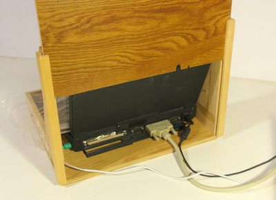 The back of the enclosure slides up to get the computer in and out, and reveal the
connectors. With the screen tilted back about 15 degrees, that leaves a good bit of space
in the back of the case for the connectors. The stepper drivers connect to the printer port,
and the computer just outputs the step waveform to the printer port.
The motor driver then just amplifies these signals.
The back of the enclosure slides up to get the computer in and out, and reveal the
connectors. With the screen tilted back about 15 degrees, that leaves a good bit of space
in the back of the case for the connectors. The stepper drivers connect to the printer port,
and the computer just outputs the step waveform to the printer port.
The motor driver then just amplifies these signals.
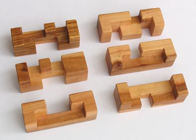 The thing that the jig ended up most useful for was making burr puzzle pieces.
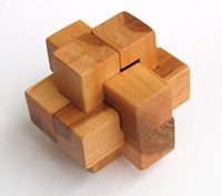 I ended up making a total of about 24 burr puzzles with it, mostly as gifts.
Though the cuts were sped up, all of the really good burr puzzle patterns
end up having inside corners in them, which can't be cut out on the table saw.
So these need to be drilled and chiseled out. After that, all the edges need to
get a slight chamfer put on them with a carving knife. Then it need varnishing, and
then a bit more tweaking still with a chisel and knife because the varnish makes some
of the gaps too small. The whole thing needs to be terribly precise to work well.
I ended up making a total of about 24 burr puzzles with it, mostly as gifts.
Though the cuts were sped up, all of the really good burr puzzle patterns
end up having inside corners in them, which can't be cut out on the table saw.
So these need to be drilled and chiseled out. After that, all the edges need to
get a slight chamfer put on them with a carving knife. Then it need varnishing, and
then a bit more tweaking still with a chisel and knife because the varnish makes some
of the gaps too small. The whole thing needs to be terribly precise to work well.
When I made my second batch of burr puzzles, I worked out that my incremental time per burr was just
over an hour for all those steps. That's actually quite low, but still nowhere
near feasible to try to sell these puzzles at a price people would be willing to pay.
Overall, I think my Screw advance box joint jig is a much better solution to cutting odd box joints. The geared indexing mechanism could also be used to precisely index the cuts for burr puzzles. My other use for this jig was cutting finely spaced finger joints, but the screw advance box joint jig does a good job of this without a computer.
See also:
Back to my Woodworking Website