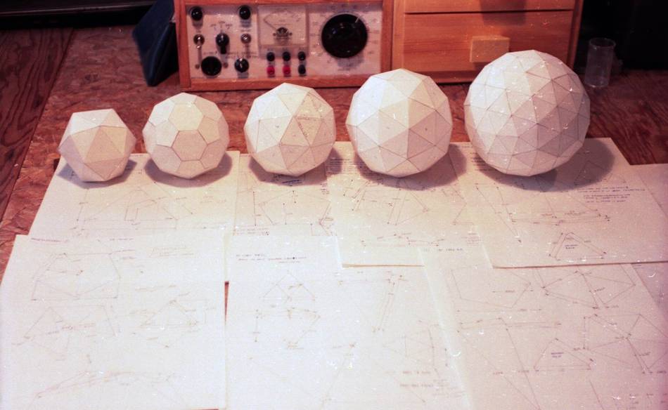
Back when I was in high school and had lots of time, I experimented
with making various types of geodesic dome shapes out of paper.
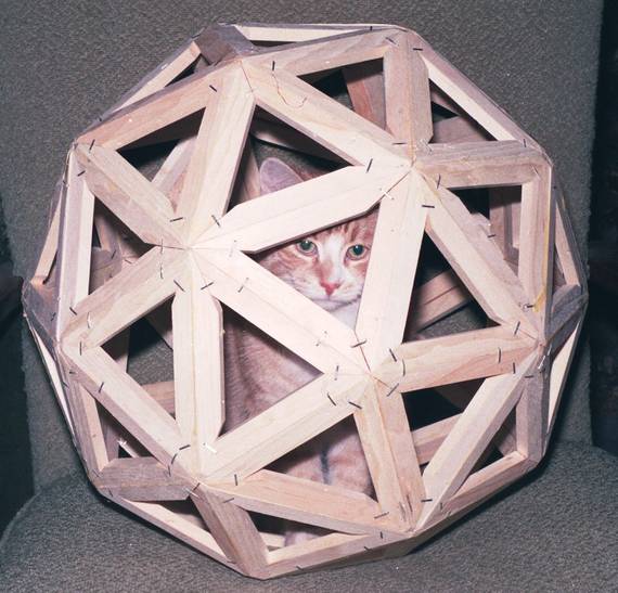
I also made a 60-sided one out of wood. I thought I'd revisit
that. I worked it all out on paper last time, but drawing it with SketchUp
today, I still needed to do a bit of trigonometry to work out some of
the angles, but at least I can be sure the geometry works out before I build it.
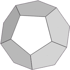
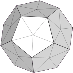
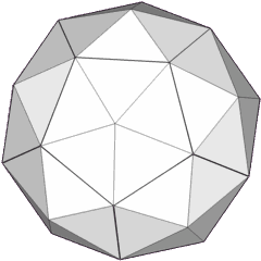
A 60 sided geodesic dome geometry can be derived from a dodecahedron
(the shape made of 12 pentagons), replacing each pentagonal face with
a shallow five-sided pyramid.
The nice thing about this shape is that all the triangles are identical
and symmetrical, which makes it easier to make.
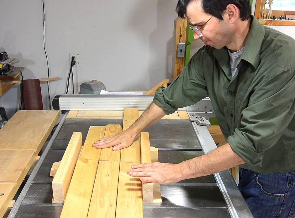
I started with some wood from a discarded futon. But the boards weren't
entirely straight, so I cut them where the bend was the most pronounced
before jointing the edges.
This is how the triangles are cut out of the boards. The cool thing is, after
bevelling both edges of the boards, the remaining sides can be cut
with just one bevel setting on the table saw, simply by flipping over the
workpiece.
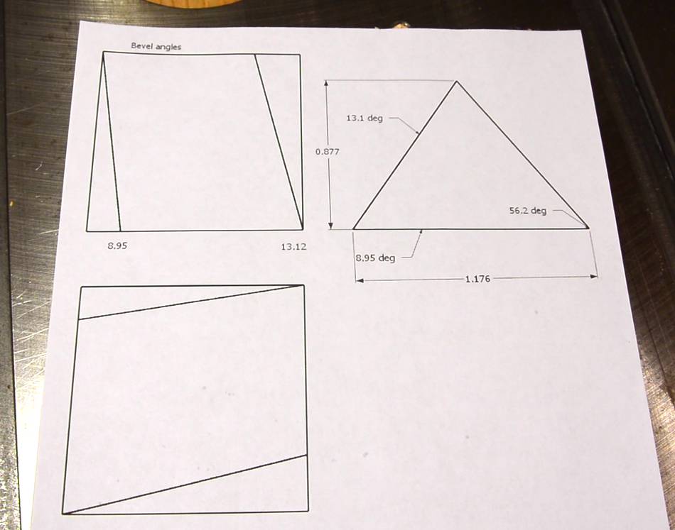
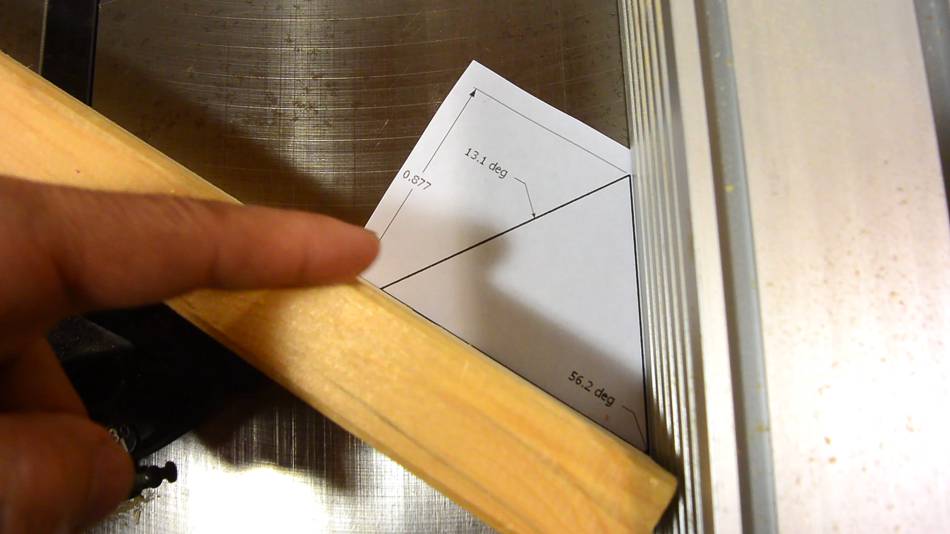
I printed off the dimensions from my CAD model, along with the angles I
needed. The angles are printed inside a square, and the square is
printed twice, once rotated 90 degrees.
Then laying the two squares on top of each other in front of the lamp, I
can check that both squares are still the same, which rules out
distortion from the printer.
If you want to build your own, I made a
PDF for you to print. In the PDF, I changed
the second square to be a mirror image instead of rotated,
figuring that might be handier. But do check that the square is square.
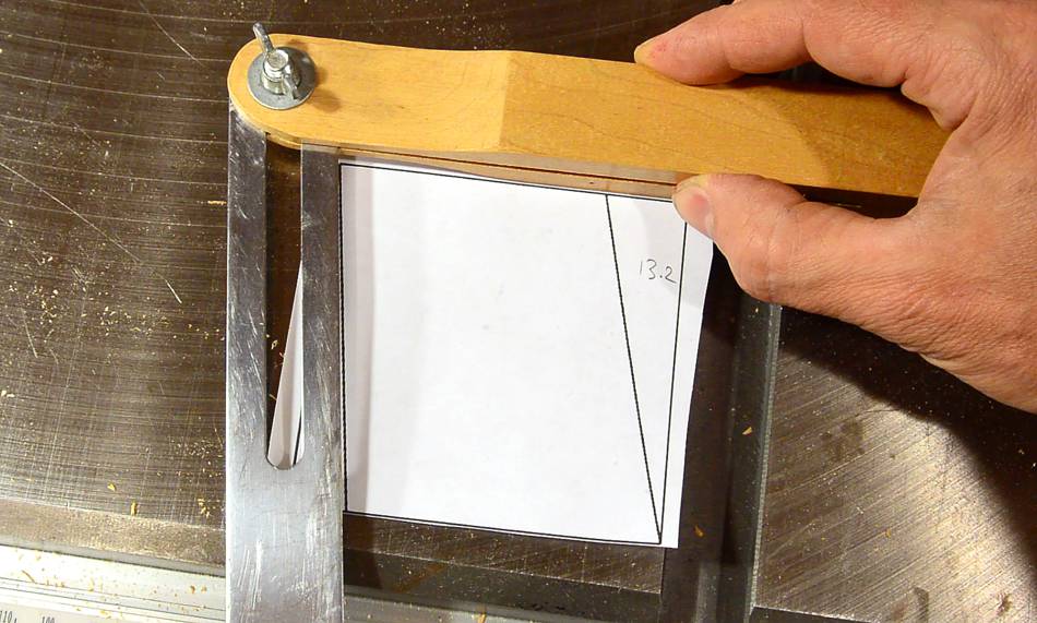
Setting a bevel gauge to the 8.95 degree angle that needs to go on the
edges of the boards.
I set the saw using the scale on the front, then checked the angle with
the bevel gauge. Close enough.
I then ripped the bevel onto both sides of the boards. The bevels are oriented
such that one bevel is facing up, the other is facing down (the two bevel
surfaces are parallel to each other).
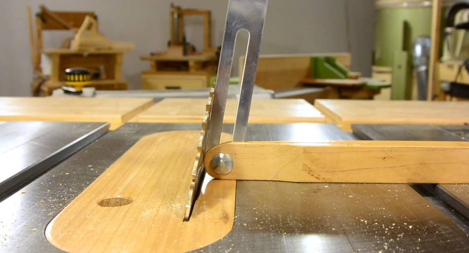
Next I set the miter gauge to the angle of the triangles, using the fence as
a reference.
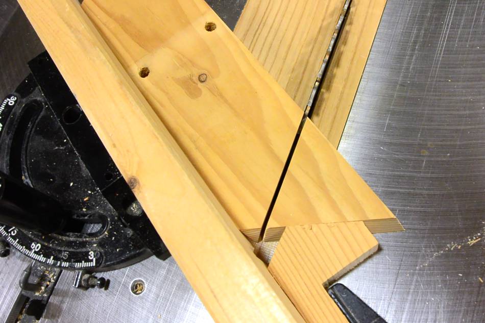
The triangles can be cut off one by one by just flipping the board upside
down (not end to end) and making another cut. Don't forget to
change the blade tilt to 13.1 degrees as well.
But then I realized it isn't quite as simple. If I just flip the board
over, there will be a piece missing from the corner of the next piece.
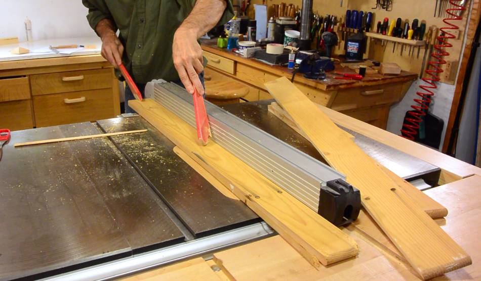
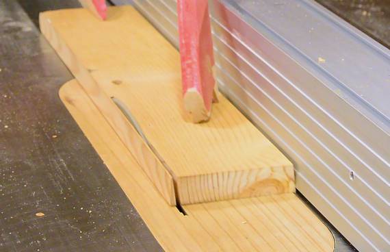
So I made a stop shaped such that after making a cut, I push the
workpiece against the stop block again and make another cut to cut
off the part with the missing corner.
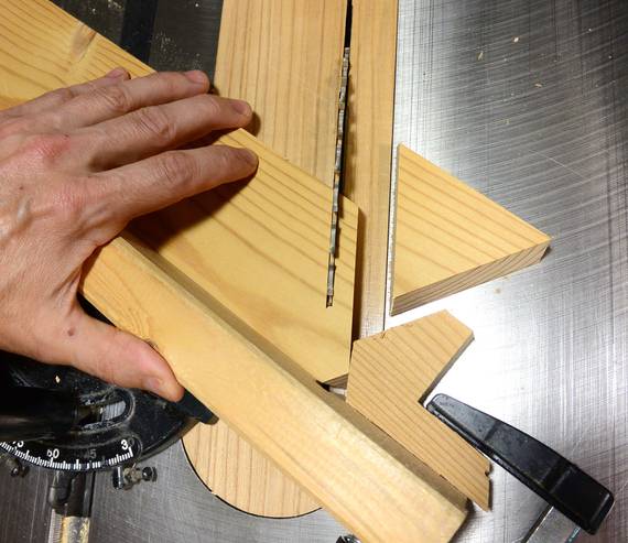
I have to say, it seems more intuitive to put the board on the
saw the wrong way. When I did that, not all the bevels on the triangles
are facing up or facing down at the same time. I made a number of scrap
triangles this way! So watch out for that mistake if you make one of
these!
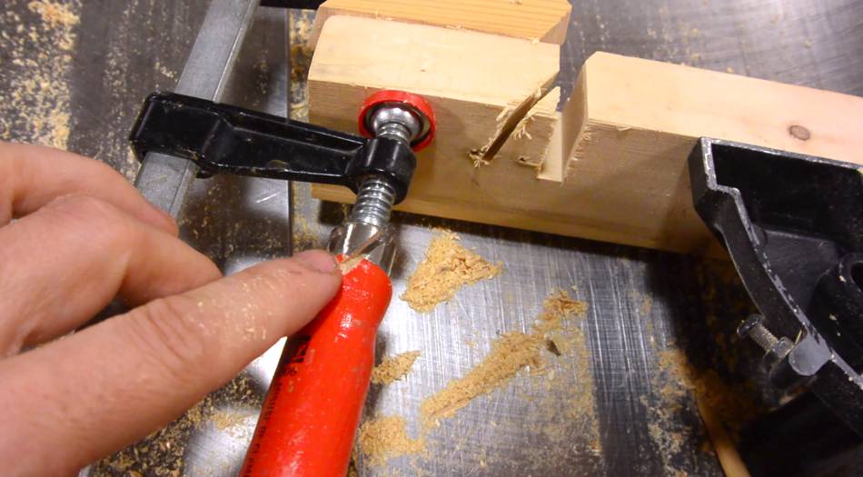
Making all these cuts, it could be easy to get careless and cut into
your fingers. A SawStop saw would be good for preventing this type of
injury. But at some point, I ended up cutting into my clamp.
That would have triggered the saw's destructive safety brake, and by
the time I replaced the cartridge and blade. I would have been out
at least $150, and a lot of time. So I'm quite happy not
having a SawStop saw!
Test fitting five pentagons. The miters for the two identical sides
(the end grain sides) look like they are just right.
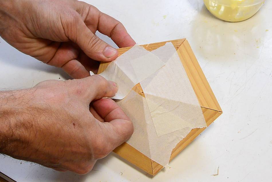
Putting it together with masking tape.
Then flipping it over and adding glue.
Then adding the last piece of tape to fix the pyramid shape.
This is my first time using tape as clamps. People have sent me
this suggestion many times, especially after
this article.
Based on my experience, I don't think using tape is a good method
for clamping. It's the best method I could think of for
this shape, but still not a very good method.
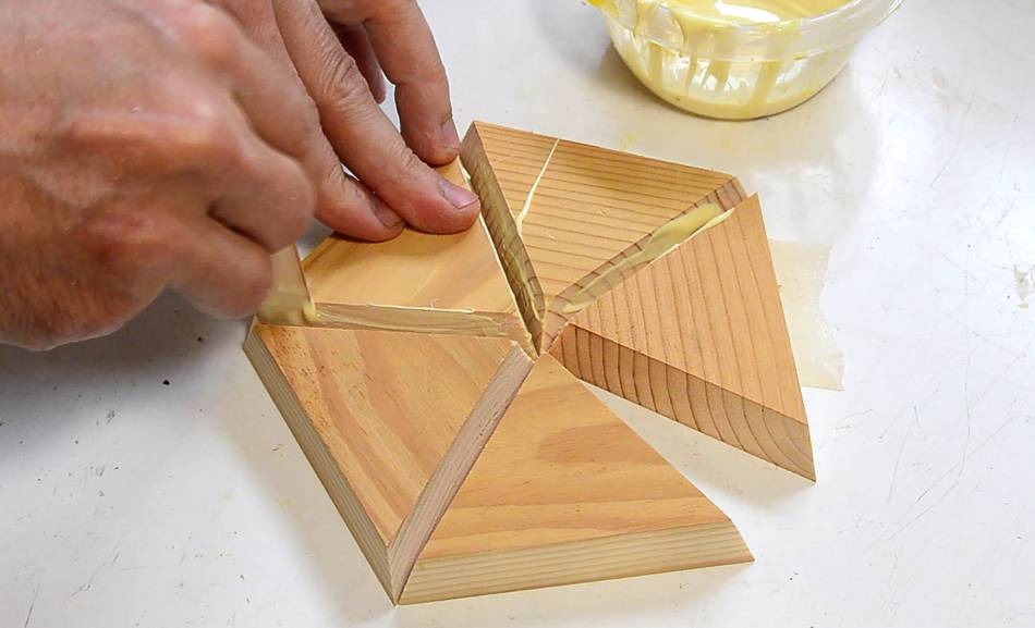
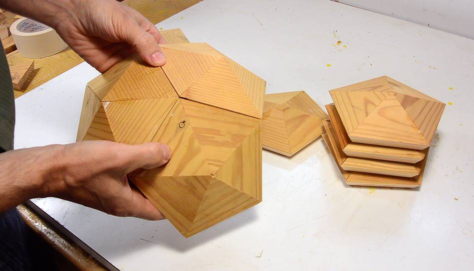
With the glue on my pentagons dry, here I'm checking how three of them will
fit together. It looks like the bevel on the bottom (long grain edge) of the
triangles is not quite right. I'm seeing some gaps on the outside.
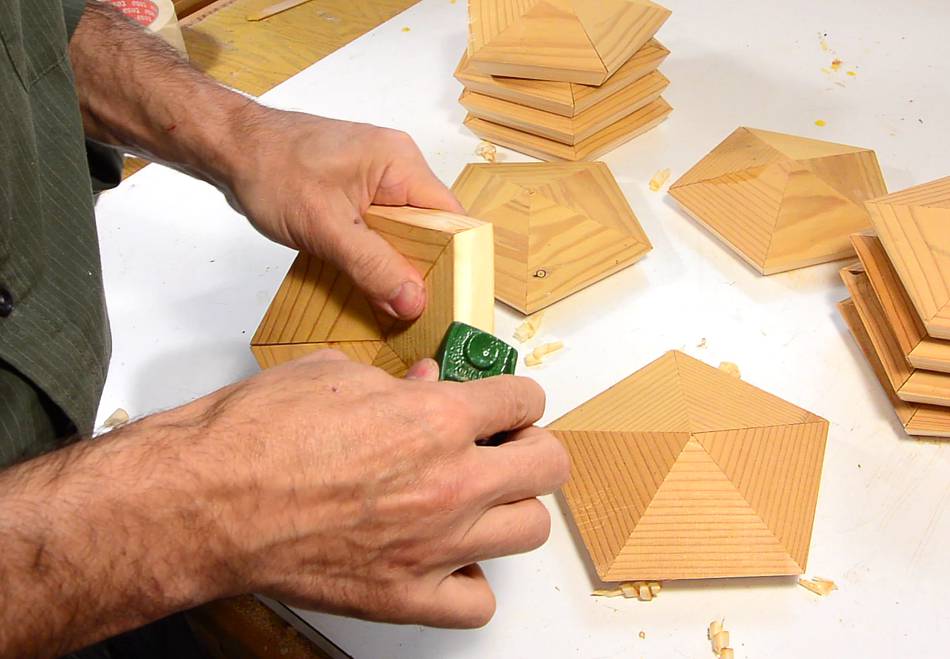
So I used a small hand plane to tweak the bevels a little. I also checked
my calculations and CAD model, and I'm sure the 8.95 degrees was the
correct angle.
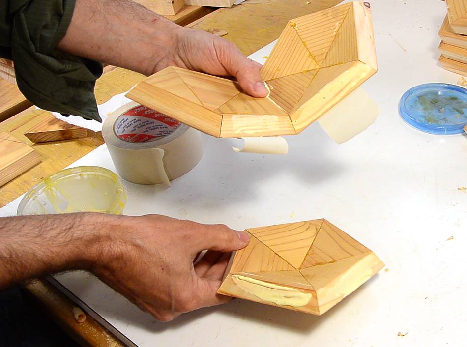
Gluing the pentagons together. The trickiest glue joint was the
first three pieces, because everything is a bit "floppy".
Subsequent pieces went in easier.
It was tempting to let the glue dry on what I already had assembled
and then add to that, but with every pentagon I added, I ended up slightly
warping what I assembled so far to accommodate the newest piece. So it's
better to keep adding pieces while the glue is still wet.
Second last piece going in.
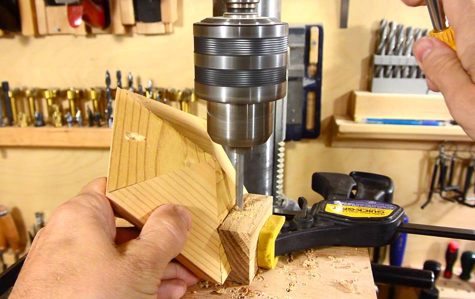
I mounted the last piece with screws instead of glue so I could still get at the
inside of it. And I'm screwing it in with pocket holes. Yes, pocket holes!
I rigged up a temporary pocket hole jig out of wood. I'm drilling 17/64"
(7 mm) holes for a #4 screw.
I'm not using a step drill, so next I have to drill a pilot hole for the
screw's shank.
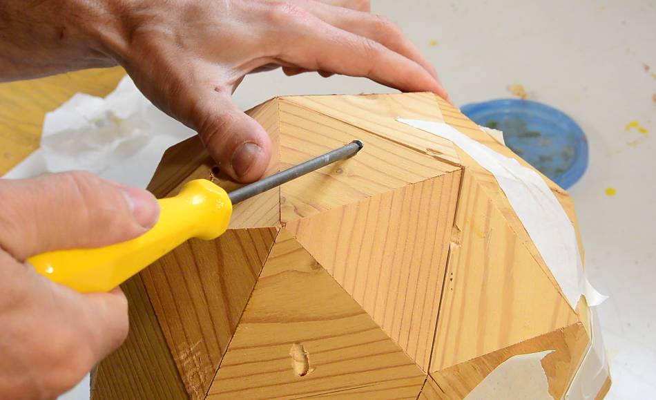
Then screwing the last pentagon in place, with just three screws. That way,
I don't have as many ugly pocket holes.
That said, the whole thing might have been easier to assemble with
pocket holes than with tape. With pocket holes, I could really pull the
pieces together. But pocket holes would have been a lot more work, and
then I'd have ugly pocket holes all over the final ball.
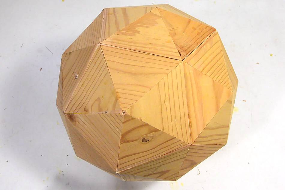
Final shape. There are a few gaps here and there. Making one of these is
tricky because you can't just check that things are square. Until final
assembly, you can't be sure that it will all fit.
The whole thing really is miter joints from hell.
I also have the SketchUp model of the ball I built.
In the CAD model, I also experimented with dividing each triangle into four
more triangles for a 240 sided geodesic dome.
 Back when I was in high school and had lots of time, I experimented
with making various types of geodesic dome shapes out of paper.
I also made a 60-sided one out of wood. I thought I'd revisit
that. I worked it all out on paper last time, but drawing it with SketchUp
today, I still needed to do a bit of trigonometry to work out some of
the angles, but at least I can be sure the geometry works out before I build it.
Back when I was in high school and had lots of time, I experimented
with making various types of geodesic dome shapes out of paper.
I also made a 60-sided one out of wood. I thought I'd revisit
that. I worked it all out on paper last time, but drawing it with SketchUp
today, I still needed to do a bit of trigonometry to work out some of
the angles, but at least I can be sure the geometry works out before I build it.
 A 60 sided geodesic dome geometry can be derived from a dodecahedron
(the shape made of 12 pentagons), replacing each pentagonal face with
a shallow five-sided pyramid.
A 60 sided geodesic dome geometry can be derived from a dodecahedron
(the shape made of 12 pentagons), replacing each pentagonal face with
a shallow five-sided pyramid.


 Wooden soccer ball
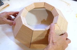 Splayed miter joints
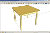 Sketchup tutorials
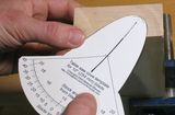 Asymmetric cove cutting
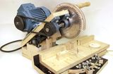
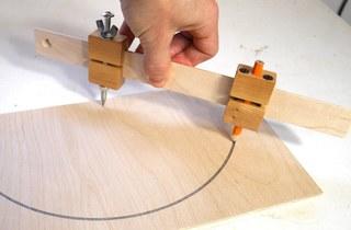 Trammel points compass