 Here’s the finished jig – or at least the first prototype:
Hi Matthias,
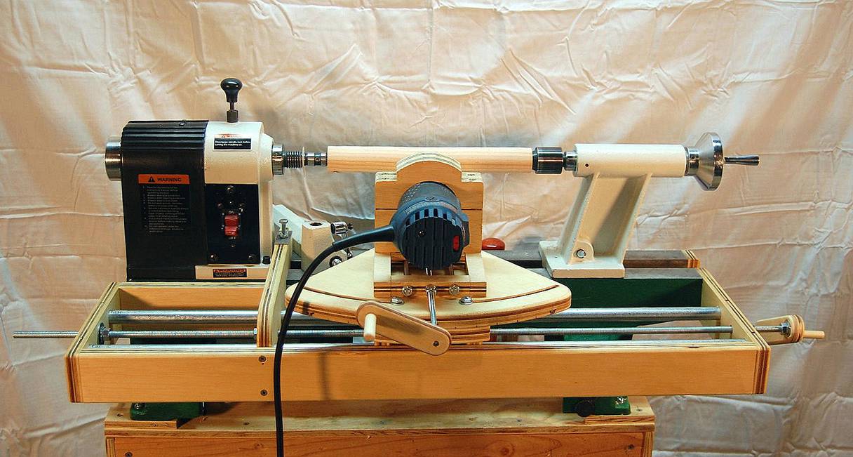
I thought you might be interested in seeing another application resulting from your gear generator. I’ve been thinking about a marble machine for a while and as part of it I wanted to have one way of lifting the marbles be done with an Archimedean screw. For that and other projects I wanted to make a machine that would cut helical spirals.
At first I considered a separate machine using the same small router I have for the 3D pantograph from your design. But, since nearly all of the parts would start out on the lathe and it already had the means to hold the object centered it would be best just to build it as an attachment to the mid-sized lathe I have. I wanted the design to allow for the full length (16”) and maximum diameter (~12”) that could be turned.
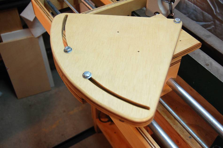
Here’s the finished jig – or at least the first prototype:
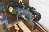
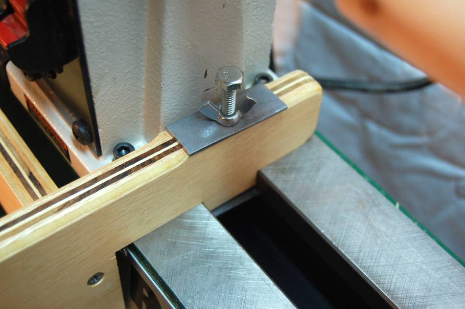 Headstock attachment point.
 It attaches to the tailstock end using threaded holes intended
for an extension bed. It was unfortunate that there aren’t similar
holes on the other end to keep the supports completely out of the way.
It attaches to the tailstock end using threaded holes intended
for an extension bed. It was unfortunate that there aren’t similar
holes on the other end to keep the supports completely out of the way.
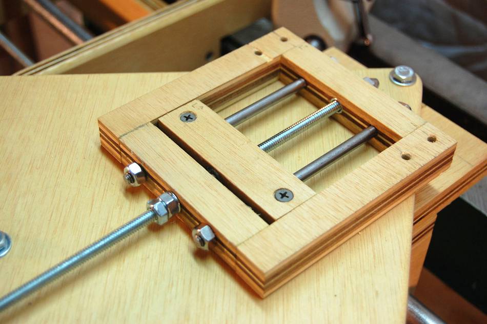
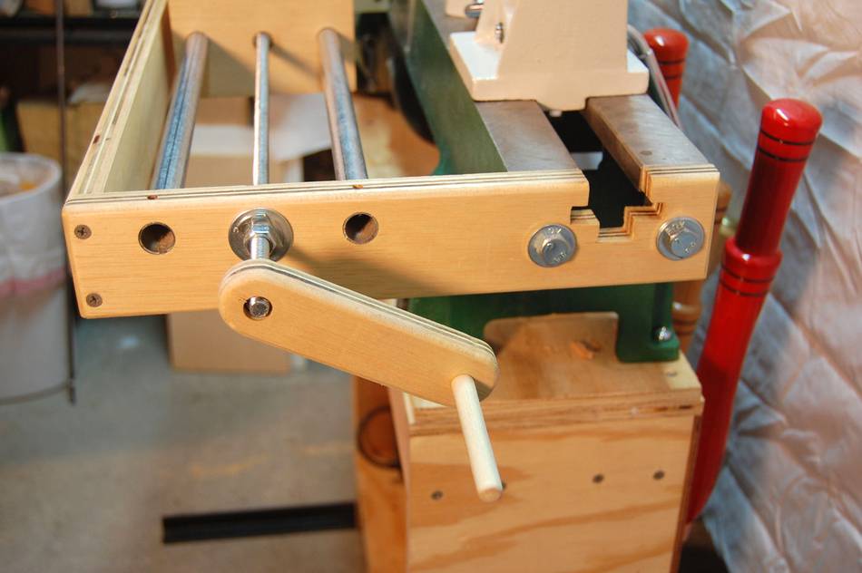 The “carriage” for the router rides on metal electrical conduit pipes –
straight and inexpensive. The threaded (3/8”-16tpi) rod drives the
carriage with two nuts embedded and epoxied in the sides, intentionally
positioned so as to minimize the backlash. I figured with 16 threads per
inch it would be easy to count turns, given most of my work is in
inches rather than metric dimensions and that metric is hard to find in
Colorado.
The “carriage” for the router rides on metal electrical conduit pipes –
straight and inexpensive. The threaded (3/8”-16tpi) rod drives the
carriage with two nuts embedded and epoxied in the sides, intentionally
positioned so as to minimize the backlash. I figured with 16 threads per
inch it would be easy to count turns, given most of my work is in
inches rather than metric dimensions and that metric is hard to find in
Colorado.
The crank was a starting point and at first I thought I was going to need some gearing or to use a variable speed drill for turning the rod but once I tried it the hand crank was just the right speed for cutting, although a bit tedious for running the carriage back from one end to the other.
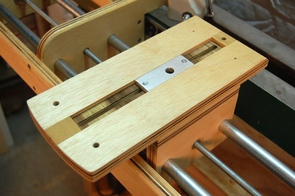 The first layer on top of the carriage is the “coarse” setting for the
diameter of the blank. This would stay fixed for any particular project
and taking care of this first avoided having to move a large amount with
the “plunge” screw. It is secured with two knobs on the underside with
threaded rods going into tapped holes in the small aluminum block.
The first layer on top of the carriage is the “coarse” setting for the
diameter of the blank. This would stay fixed for any particular project
and taking care of this first avoided having to move a large amount with
the “plunge” screw. It is secured with two knobs on the underside with
threaded rods going into tapped holes in the small aluminum block.
 The next level is a rotatable piece which will allow the router bit to
enter at an angle if the project requires. I put the center of rotation
as directly under the bit position as possible so it would not
hinder reaching both ends of the blank. Most projects won’t require
this so I also made a fixed piece that will reduce the total play
a small amount.
The next level is a rotatable piece which will allow the router bit to
enter at an angle if the project requires. I put the center of rotation
as directly under the bit position as possible so it would not
hinder reaching both ends of the blank. Most projects won’t require
this so I also made a fixed piece that will reduce the total play
a small amount.
 Next is a “plunge” adjustment which has about 2Ľ inches of movement. The
center piece attaches to the layer below and a threaded (1/4”-20tpi) rod
going through fixed nuts moves the outer square. In the end this had
more movement than I wanted so a slight redesign is in order to keep the
square part better aligned and less susceptible to wobble from a very
slightly bent rod.
Next is a “plunge” adjustment which has about 2Ľ inches of movement. The
center piece attaches to the layer below and a threaded (1/4”-20tpi) rod
going through fixed nuts moves the outer square. In the end this had
more movement than I wanted so a slight redesign is in order to keep the
square part better aligned and less susceptible to wobble from a very
slightly bent rod.
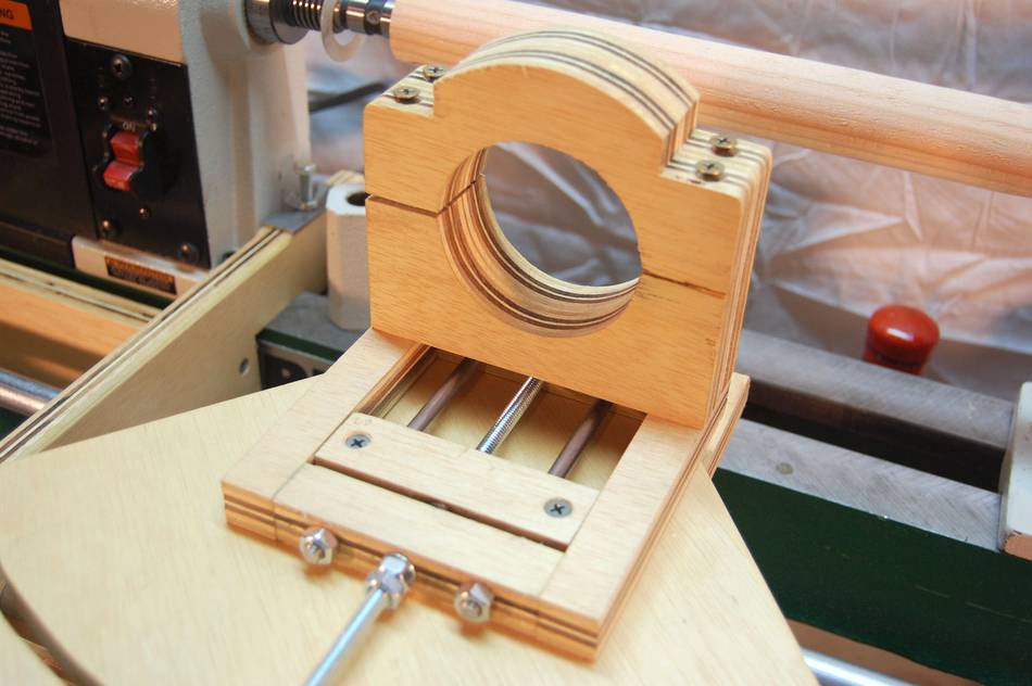 Last is the mounting for the router, a Bosch “Colt”.
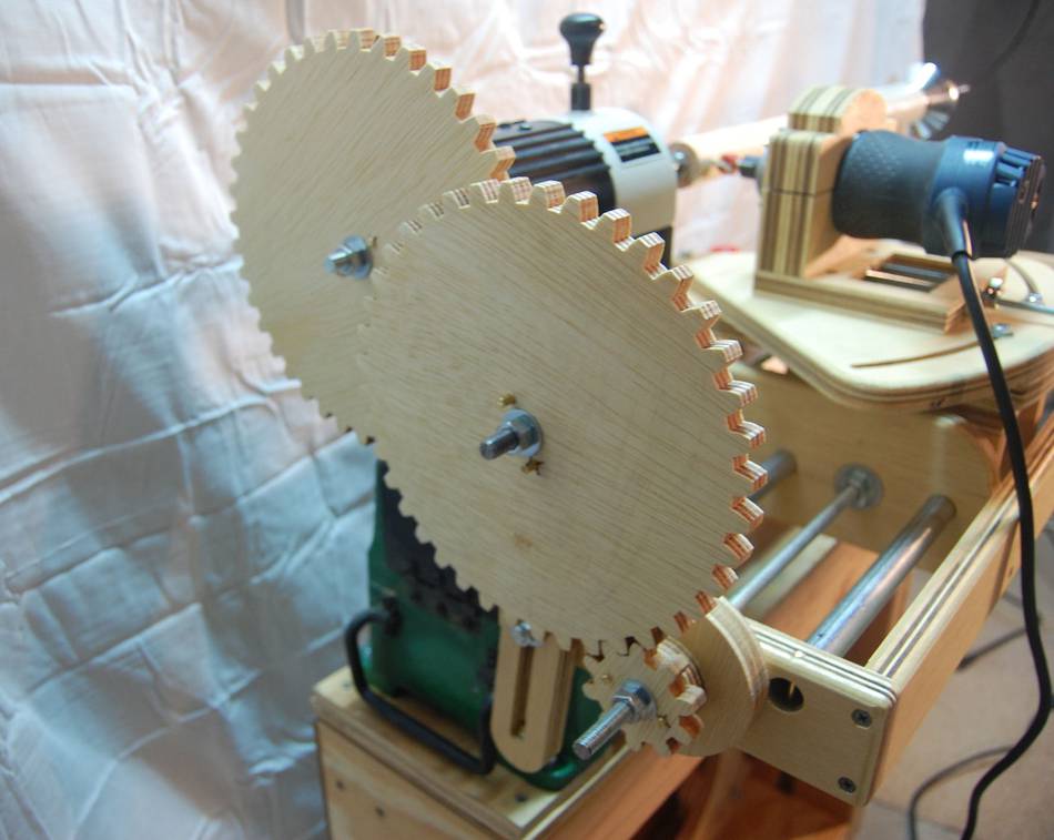
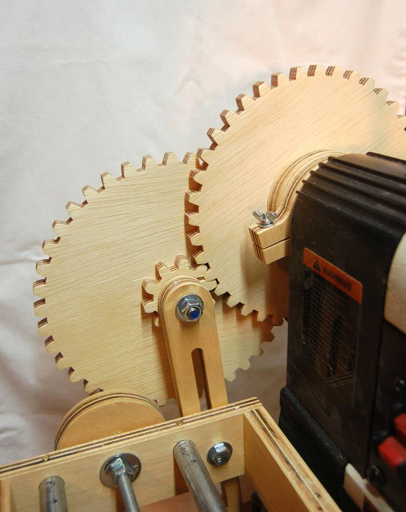 Here are two views of the gearing mechanism on the headstock end. As a
starting point I picked ratios that would give me a divide by 16 (10:40
teeth, for 1:4, twice) and produce one turn of the lathe for 1 inch of travel of the
router. The center pair of gears is held on an adjustable arm so they
act as an idler, allowing other combinations of gears, as long as the
total radii of the gears is enough to span the distance between the
drive rod and the lathe center. Eventually I will modify the design to
accommodate a single “reverser” gear in the drive path so I can make
both right and left-hand spirals.
Here are two views of the gearing mechanism on the headstock end. As a
starting point I picked ratios that would give me a divide by 16 (10:40
teeth, for 1:4, twice) and produce one turn of the lathe for 1 inch of travel of the
router. The center pair of gears is held on an adjustable arm so they
act as an idler, allowing other combinations of gears, as long as the
total radii of the gears is enough to span the distance between the
drive rod and the lathe center. Eventually I will modify the design to
accommodate a single “reverser” gear in the drive path so I can make
both right and left-hand spirals.
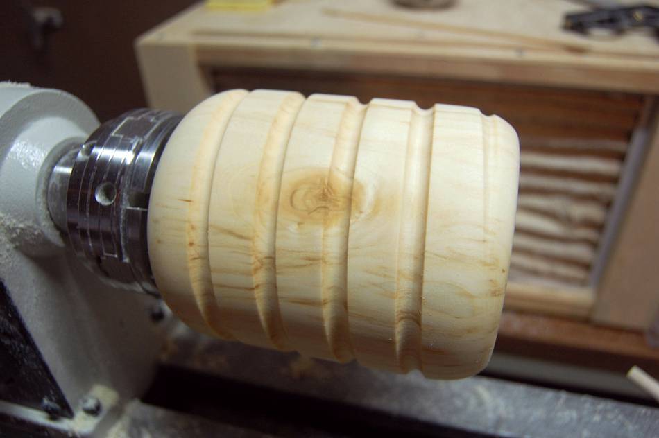
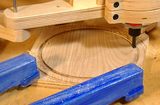
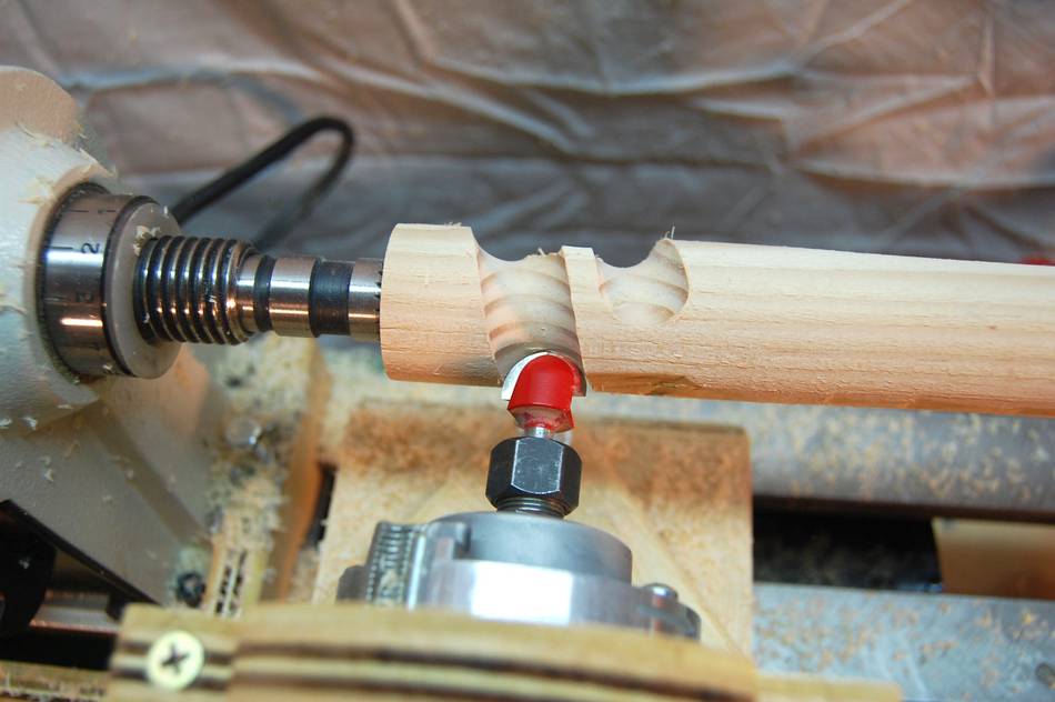 Here is a photo of the first cutting. I “rewound” a couple of times to
gradually increase the depth. Unfortunately the piece from a pine 2x4
split at a knot.
Here is a photo of the first cutting. I “rewound” a couple of times to
gradually increase the depth. Unfortunately the piece from a pine 2x4
split at a knot.
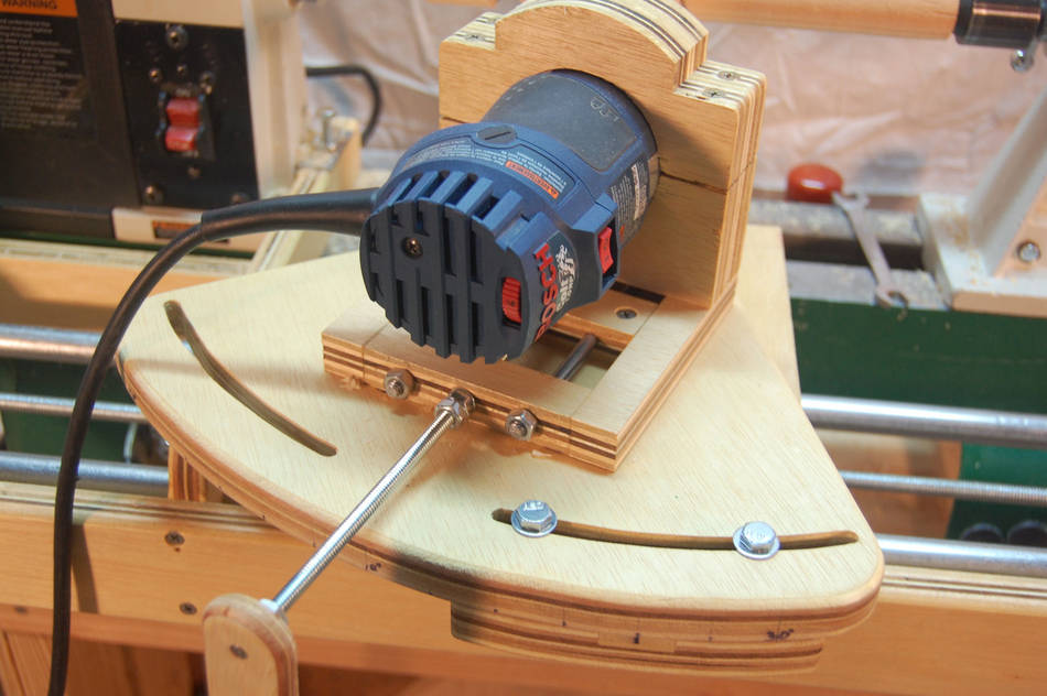 Here it is set up for an angled cut of 20 degrees:
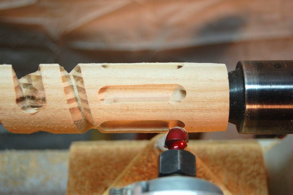 By disconnecting the gears and using the indexer on the lathe I can cut
flutes in the piece. I’ve found I have to pay very close attention to
what I’m doing to avoid going the wrong way with the plunge depth after
a cut. Also, I need to develop a habit of carefully counting the number
of turns of the drive and the plunge cranks for repeatability. Also
shown is a V groove and an angled cut with a straight bit.
By disconnecting the gears and using the indexer on the lathe I can cut
flutes in the piece. I’ve found I have to pay very close attention to
what I’m doing to avoid going the wrong way with the plunge depth after
a cut. Also, I need to develop a habit of carefully counting the number
of turns of the drive and the plunge cranks for repeatability. Also
shown is a V groove and an angled cut with a straight bit.
 Matthias commets:
I have that same turns-counting problem on my slot mortiser when making multiple mortises. The counting wheel worked out quite well.
 Beri's homemade lathe
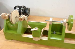 Homemade wooden lathe, from scratch
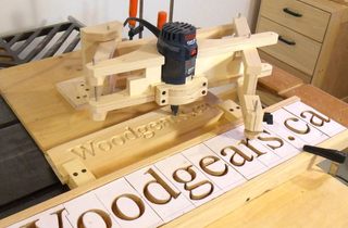 3D router pantograph
 Cutting circles with the router pantograph
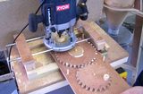 Stephen's router wheel lathe
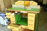 More reader projects