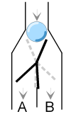
 The classic way to do this is with an inverted Y that rotates in the track. Each marble, on
exiting the fork, flips the Y, causing the next marble to take the other path.
The classic way to do this is with an inverted Y that rotates in the track. Each marble, on
exiting the fork, flips the Y, causing the next marble to take the other path.
The classic way to do this is with an inverted Y that rotates in the track. Each marble, on
exiting the fork, flips the Y, causing the next marble to take the other path.
This shape is hard to make out of Lego. My attempt at building this worked, but it was
big and inelegant, and the force of the marbles hitting the tail of
the 'Y' would cause it to frequently disassemble itself.
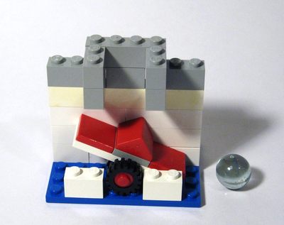 So I modified the design such that the force of the falling marbles would, if anything
only press the Lego together. I came up with a very minimalist Lego seesaw design.
So I modified the design such that the force of the falling marbles would, if anything
only press the Lego together. I came up with a very minimalist Lego seesaw design.
The one at left is built with one side open to better illustrate how it goes together. This seesaw design proved itself to be very durable and reliable. And as an added advantage, the marbles come out the left and right, so less vertical height is lost, leaving more height for the marble tracks.
Naturally, the next logical thing to do is to cascade several of these together
so that the stream of marbles is split into more than two directions.
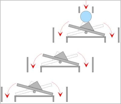 If we arrange several dividers all off to one side as shown, (each one off-set
to one side) and keep dropping marbles in the top, every marble will flip the
uppermost rocker, every second the rocker below that, and every fourth
marble will flip the bottom rocker. If we interpret a rocker that
is rocked to the left as a 'zero' and one rocked to the right as a 'one',
then the rockers represent a binary count of the number of marbles dropped
in the top. So already, we have something that we could consider a counter.
If we arrange several dividers all off to one side as shown, (each one off-set
to one side) and keep dropping marbles in the top, every marble will flip the
uppermost rocker, every second the rocker below that, and every fourth
marble will flip the bottom rocker. If we interpret a rocker that
is rocked to the left as a 'zero' and one rocked to the right as a 'one',
then the rockers represent a binary count of the number of marbles dropped
in the top. So already, we have something that we could consider a counter.
We can increase the counter's value by two at a time by dropping marbles directly onto the middle rocker, or by fours by dropping them directly onto the third rocker. Moving from 'counter' to 'adder' is just a matter of controlling which rockers the marbles fall onto.
However, if such an 'adder' were to become part of a larger marble computer, it would still
be necessary to have some means of transmitting the state of the counter as a pattern of marbles.
I spent some time thinking about this, and came up with a simple way to retain the marble
in the adding element. That way, the computer's stored number could be released
as a series of marbles when the counter is 'read out'.
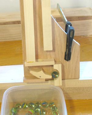 The single rocker at left is a refined version of the Lego prototype. Marbles are dropped in from
the top. The horizontal piece of wood above the rocker has a hole in it to align the marbles
accurately before they fall onto the rocker.
The single rocker at left is a refined version of the Lego prototype. Marbles are dropped in from
the top. The horizontal piece of wood above the rocker has a hole in it to align the marbles
accurately before they fall onto the rocker.
The cavity to the right of the rocker keeps the marble from falling out until the rocker is rocked back to the left. This one-bit counter is shown in a state of a '1' (rocker rocked to the right). When the counter is reset, by manually flipping the rocker back to the left, the marble in the cavity to the right can roll out and is released as the counter value.
Getting this to work reliably is tricky, and I experimented with different shapes for the rocker and cavity. But as it turned out, the original Lego rocker shape was close to ideal, and I ended up nearly copying its dimensions. The cavity needs a gentle slope to hold the marble so that it doesn't push too hard against the rocker, and the granularity of Legos was just a bit too coarse to prototype that aspect.
If you want to build your own adding machine, I highly recommend prototyping a one-bit adder first, because getting this to work reliably is tricky. It's best to assemble it with just hot glue, so that it's possible to pry pieces off when making alterations. Also note the relatively high drop at the top of this prototype. With the marbles falling a fair distance before hitting the hole on the left most (most significant) bits, I found the marble would on occasion bounce off the rims of the hole, so testing it with a large drop is helpful for debugging that.
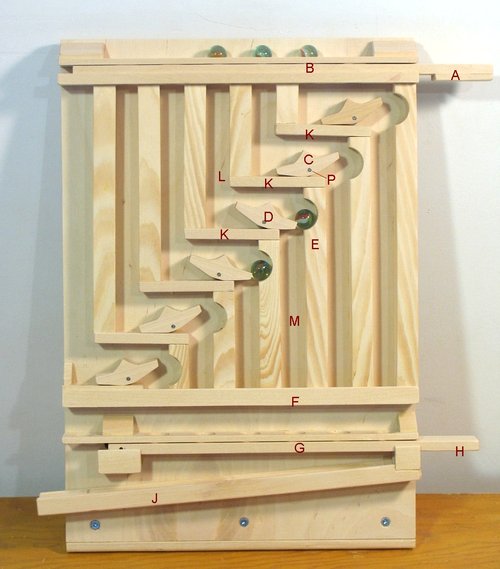 The number to add is placed on the inputs at the top of the machine B.
There is a hole for each bit position. The holes are blocked by a slider A.
When this slider is pushed in (to the left), its holes align with those in the machine,
allowing the marbles to fall through.
The number to add is placed on the inputs at the top of the machine B.
There is a hole for each bit position. The holes are blocked by a slider A.
When this slider is pushed in (to the left), its holes align with those in the machine,
allowing the marbles to fall through.
The internal state of the machine is held by the toggles, such as C and D. Toggle C is in a '0' state, while toggle D is in a '1' state. Toggles in the 1 state have a captive marble E
Above each toggle is a hole K exactly above the pivot P of the toggle. The role of the hole is to make sure that the marble falls straight and directly onto the toggle.
When a marble falls onto a toggle in the '0' state such as C, the marble is deflected to the right by the toggle's peak. It then rolls off to the right, causing the toggle to flip to the right, and trapping the marble, such as in position E. This results in a '1' being stored such as the toggle in position D.
When a marble falls onto a toggle in the '1' state, the marble is deflected to the left. It rolls off to the left, causing the toggle to flip and release the captive marble in position E. After rolling off the toggle, the marble falls through the hole K to the left of the toggle, and onto the top of the next toggle. The marble effectively acts as a carry, adding a '1' to the bit in the next most significant position.
In addition to the carry marble, an input marble may also fall onto the same hole K through path L. However, the carry marble is always slightly delayed compared to the marble falling directly down path L so that the marbles will not jam each other trying to fall down the same hole at the same time.
When a toggle flips from a '1' to a '0', the captive marble is released and falls down path M. The marble must pass through a hole at position F which helps to steady the marble, before falling through the holes in position G and rolling off the ramp J into a container.
To release the result from the machine, and reset it, the result slider H is pushed to the left. This first closes the holes at G, and then forces all the toggles to the left, releasing all the marbles held in the machine down path such as M, through hole F, to finally come to rest above the holes at G, which are blocked by the slider which was moved left.
Once the result is read, the slider is moved back to the right. This releases all the
marbles down ramp J, and also unblocks all the toggles.
The machine is left with all zeros in it and ready for the start of another addition.
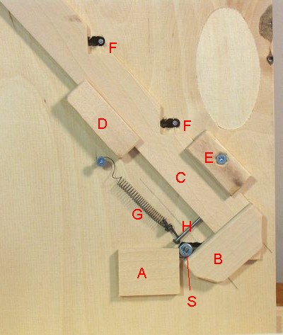 The reset mechanism is on the back of the machine. A screw S on the slider protrudes
through the plywood base of the machine. When the slider is moved left (right as seen from the back),
the screw pushes block B diagonally down to the right.
This block is attached to the reset bar C.
which slides diagonally, held by blocks D and E. In sliding down
towards the right, and pushes the nails, which protrude through slots at F. The bar forces the
nails to the right.
The nails are part of the toggles of the machine, and thus force the toggles to flip to the right
(or to the left as seen from the front). This puts the toggles back in the '0'
position, and releases any captive marbles they may have held.
Once the result slider is pulled back out (to the left as seen from the back), bar C
is pulled back by spring G, which pulls on the nail H in the bar.
Finally, the slider slides until the screw S hits block A,
which ensures that when the slider is pulled out, it stops at the position where its holes
(on the front side) line up with the holes in the rail above it, allowing any result marbles to
fall out of the machine.
The reset mechanism is on the back of the machine. A screw S on the slider protrudes
through the plywood base of the machine. When the slider is moved left (right as seen from the back),
the screw pushes block B diagonally down to the right.
This block is attached to the reset bar C.
which slides diagonally, held by blocks D and E. In sliding down
towards the right, and pushes the nails, which protrude through slots at F. The bar forces the
nails to the right.
The nails are part of the toggles of the machine, and thus force the toggles to flip to the right
(or to the left as seen from the front). This puts the toggles back in the '0'
position, and releases any captive marbles they may have held.
Once the result slider is pulled back out (to the left as seen from the back), bar C
is pulled back by spring G, which pulls on the nail H in the bar.
Finally, the slider slides until the screw S hits block A,
which ensures that when the slider is pulled out, it stops at the position where its holes
(on the front side) line up with the holes in the rail above it, allowing any result marbles to
fall out of the machine.
It's hard to find a spring soft enough for this purpose. A rubber band would work just as well, though rubber bands do tend to go bad after a few years.
The diagonal slider is a piece of birch 5 mm thick and 23 mm wide. It's best to size this off your machine,
rather than from plans. To get the location of where the notches need to go, just push the piece against
the nails, and mark where the nails touch it to know where to cut the notches.
![]() To get the layout onto my piece of plywood, I took my 1:1 printout and clamped it onto the piece
of plywood that was to become the back of the machine.
I used an awl to punch the centers of all the holes that needed drilling through the template and onto the wood.
I also transferred the positions of key corners by pushing a chisel onto the lines,
which cut through the paper and left a shallow cut in the wood.
If you build your own machine, be sparing in how many spots you mark
and circle where on the paper template you punched through as it can be difficult to figure out which
mark is which once the paper template is removed. The punched through edges are hard to spot on
the paper template afterwards if you don't circle them.
To get the layout onto my piece of plywood, I took my 1:1 printout and clamped it onto the piece
of plywood that was to become the back of the machine.
I used an awl to punch the centers of all the holes that needed drilling through the template and onto the wood.
I also transferred the positions of key corners by pushing a chisel onto the lines,
which cut through the paper and left a shallow cut in the wood.
If you build your own machine, be sparing in how many spots you mark
and circle where on the paper template you punched through as it can be difficult to figure out which
mark is which once the paper template is removed. The punched through edges are hard to spot on
the paper template afterwards if you don't circle them.
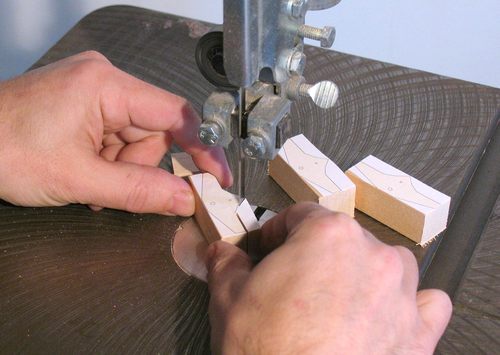 I also made six paper templates for the toggles. I glued these onto the pieces of wood that I
cut the toggles out of, and cut them out with a band saw. After I cut them out and drilled
the holes, I just sanded off the paper template.
I also made six paper templates for the toggles. I glued these onto the pieces of wood that I
cut the toggles out of, and cut them out with a band saw. After I cut them out and drilled
the holes, I just sanded off the paper template.
 Next I cut the pieces for the overall layout.
I used birch for all the horizontal pieces. It's a closed grain hardwood and doesn't
stand out too much. Maple would be just as suitable as birch.
For the uprights, I just used spruce cut from 2x4's.
I cut pieces wide enough
for two uprights, and drilled the 1 1/8" holes with a forstner bit in them, then cut them down the middle.
The holes are much easier to drill that way. Don't try to cut the 1 1/8" holes with a spade bit.
If you don't have a 1 1/8" forstner bit, cut the rounds out with a fine band saw blade
or a scroll saw.
Next I cut the pieces for the overall layout.
I used birch for all the horizontal pieces. It's a closed grain hardwood and doesn't
stand out too much. Maple would be just as suitable as birch.
For the uprights, I just used spruce cut from 2x4's.
I cut pieces wide enough
for two uprights, and drilled the 1 1/8" holes with a forstner bit in them, then cut them down the middle.
The holes are much easier to drill that way. Don't try to cut the 1 1/8" holes with a spade bit.
If you don't have a 1 1/8" forstner bit, cut the rounds out with a fine band saw blade
or a scroll saw.
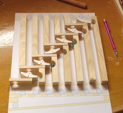
The photo at left shows me doing a check of the parts on the paper layout. I hadn't cut
the uprights to their final length yet when I did that.
 It's important to de-burr all the holes. In this photo, I'm cutting a chamfer on the edge of
one of the holes. I have to do this so that the knife is always pulling out of the grain.
It's important to de-burr all the holes. In this photo, I'm cutting a chamfer on the edge of
one of the holes. I have to do this so that the knife is always pulling out of the grain.
For my original machine, I used a 5/8" forstner drill bit. Only about half the marbles I tried would pass through a 5/8" hole, so I had to carefully sort the marbles. I also had to be very careful because even the slightest burr on any of the holes could get the marbles stuck.
For this machine, I used a 11/16" drill. It's not a common size, so it needs to be bought or mail ordered from a woodworking supply place. I got mine from Lee Valley Tools, but you could can also mail order it from places such as rockler.com, woodcraft.com, leevalley.com or amazon.com.
I wouldn't recommend going any larger than 11/16". The holes serve to align the marbles
at various points in the machine, and if you went to 3/4", they wouldn't align the marbles very well.
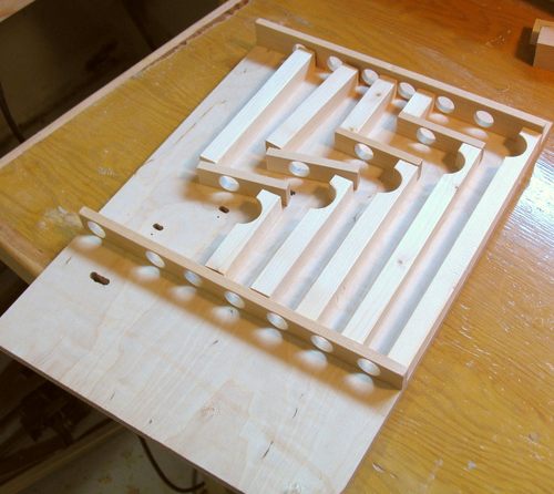 After cutting out the parts, the next step is to glue everything together.
It's enough to just use carpenters glue and glue the pieces straight down on the plywood.
After cutting out the parts, the next step is to glue everything together.
It's enough to just use carpenters glue and glue the pieces straight down on the plywood.
For the main part of the machine, I glued down the rails at the top and bottom first, along with the rightmost upright. After the glue for those dried, I glued in the sets of two uprights and one horizontal for each bit position. The image shows the two leftmost sets of parts just loosely positioned (not glued yet).
To mount the slider for releasing the marbles on top, I added a temporary spacer made of
cereal box cardboard to the slider, and then glued the rail that goes above the slider
pressed against that. That way, there will be enough slack for the slider to slide freely.
Use the same approach for mounting the support blocks for the result slider on the bottom.
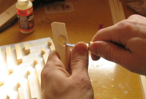
 I used 1 1/4" finishing nails for the pivots of the toggles. I drilled 3/64" holes in the toggles,
which allows the toggle to spin freely on the nail. I also drilled 3 mm (1/8") into the front
with a 3/32" drill, so that the nail head can be recessed into the toggle.
The pivot nail is nailed into the back panel, into a pre-drilled 1/32" pilot hole.
I also drilled a 1/32" pilot hole for the other nail, which is used for the reset mechanism.
This nail protrudes through the elongated holes above the pivot in the back panel.
I used 1 1/4" finishing nails for the pivots of the toggles. I drilled 3/64" holes in the toggles,
which allows the toggle to spin freely on the nail. I also drilled 3 mm (1/8") into the front
with a 3/32" drill, so that the nail head can be recessed into the toggle.
The pivot nail is nailed into the back panel, into a pre-drilled 1/32" pilot hole.
I also drilled a 1/32" pilot hole for the other nail, which is used for the reset mechanism.
This nail protrudes through the elongated holes above the pivot in the back panel.
To make a base for the machine, bevel the edge of a piece of 2x6 at 17 degrees, and screw the machine to it. Hopefully, this angle should be sufficient to keep the marbles from getting ejected out the front of the machine. If you find the marbles falling out the front, it may help to carve out the back edges of some of the holes that the marbles pass through, or just to increase the lean of the machine.
Chances are, your machine may need a little bit of debugging after you finish it to get it working perfectly.
 My original page about the adding machine (version 1)
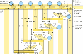 Plans for the marble adding machine (version 2)