A friend, Joel, recently asked me about how to calculate the miters for making
a sort of tapered cylinder out of wood segments. For example, for a straight
eight sided cylinder, the pieces need to be bevelled at 22.5 degrees.
But when the cylinder is tapered, that same 22.5 degree bevel leaves gaps on the inside.
Joel works in a high school wood shop, so first he turned to the math teachers at his school,
but they weren't able to give him an answer. When he showed me the high school
wood shop he works in, he asked me if I knew anything about how to work it out.
I knew about the problem, but hadn't had a reason to work out the math for it so
far. Looking around the web, I couldn't readily find a site that already had it worked
out, so I thought it might be a fun thing to cover on this site.
I worked out the math for it. It's a lot of trigonometry. All based on high school
math but, at the same time, no doubt too much for most high school math teachers.
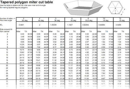
A number of people have asked about the math for the claculations.
I worked it out on paper, and then made a Sketchup drawing to verify
my calculations. I also typed the formulas into the Sketchup model so I wouldn't
lose them. You can enlarge the image at left to for a better view.
You can also download the sketchup CAD model for
this drawing to have a closer look (you need to install the free
Google Sketchup to open the CAD model)
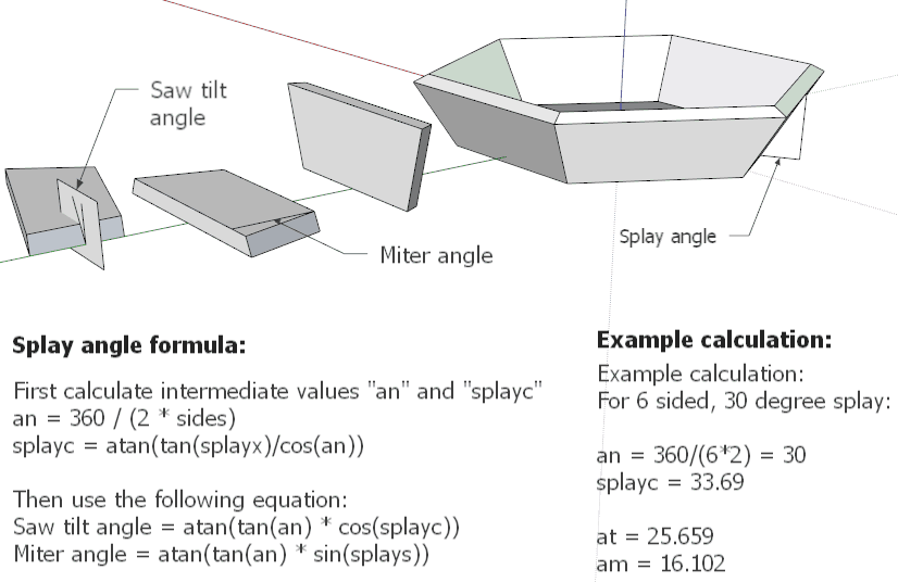
The values "splayc" and "splays" at left are inrmediate values and don't
represent any useful physical measurement. They are just there to simplify
the calculation. If that is too difficult, either don't use the formulas
or ask a friend who is good at math, because I'm afraid I don't have
time to teach you math.
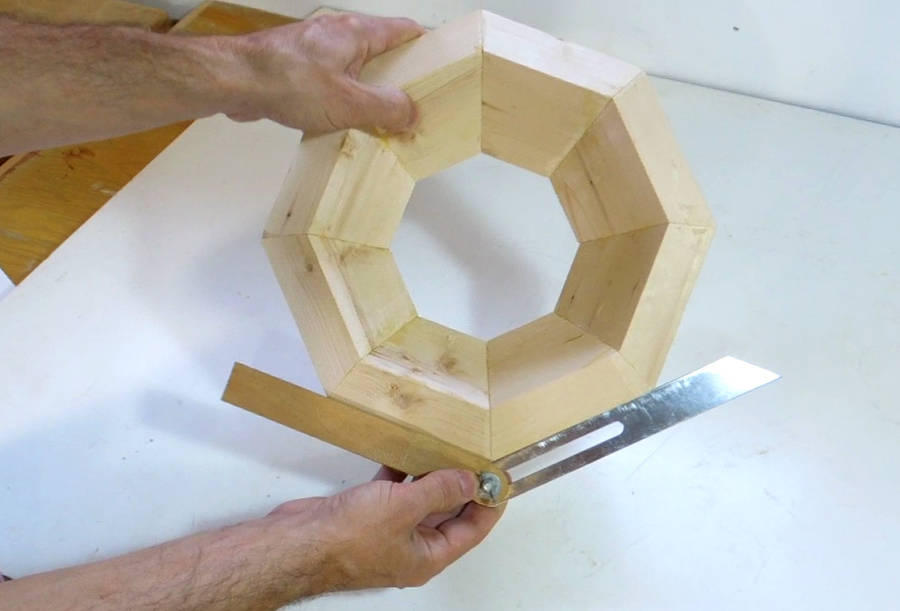
To try my calculations on a real workpiece,
I made an octagon, tapered by 30-degrees.
Looking at it from the top, the angles around the outermost edge are
all 45 degrees (or 22.5 on each piece).
But looking at it along the joint, that 45 bevel gauge set to 45 degrees no longer
fits the joint. The more the shape is tapered, the closer to 90 degrees the miters become.
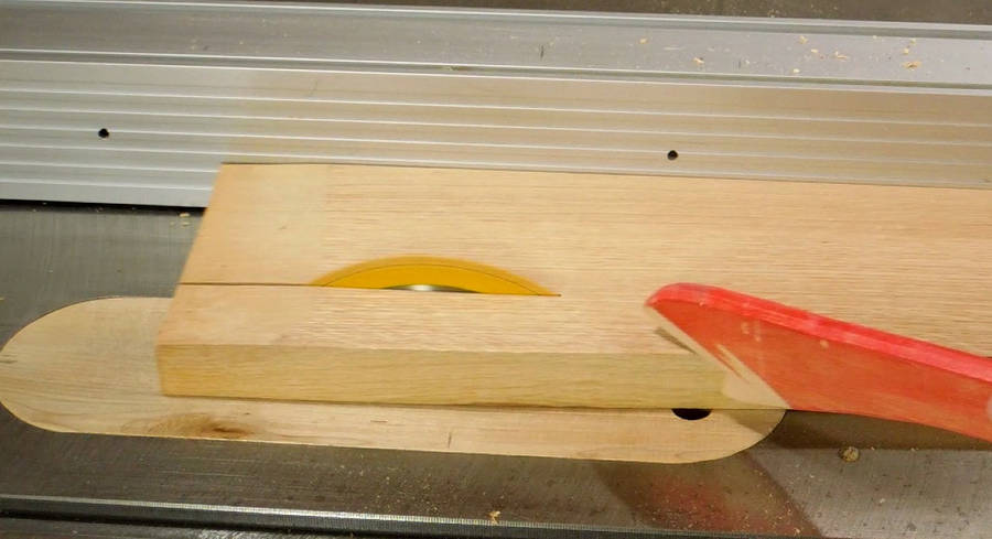
I had cut the test pieces using my miter saw. But I'm really no fan of using a miter saw,
especially for small pieces, where it's difficult to secure the workpiece against the low fence.
For my second piece, I went back to using the table saw.
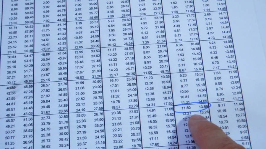
For my next piece, I chose ten sides, and a 40-degree taper angle. Looking up the angles on my
spreadsheet, the miter comes to 11.8 degrees, and the saw needs to be tilted by 13.69 degrees.
Note that the miter and blade tilt angles apply the same way on the miter saw as on the table saw.
I chose some nice clear red oak this time. The oak was from firewood, but the shortness
of my stock didn't matter much because I needed to cut it into even shorter pieces.
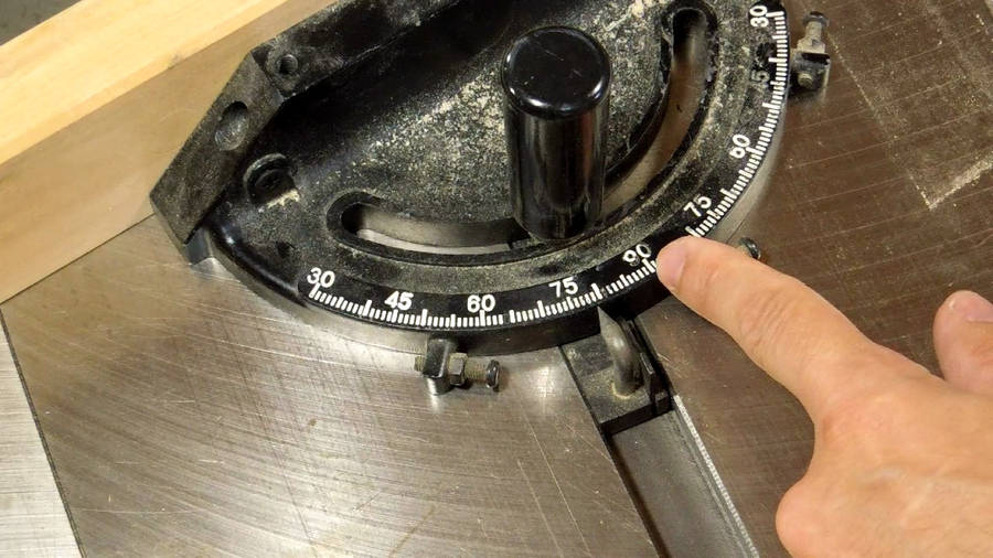
Setting the miter angle. Experience has shown that the scale on the miter gauge that
came with my Delta hybrid saw is surprisingly
trustworthy. I'm always amazed how people swap these out for the costly Incra ones
that are only made of bent sheet metal.
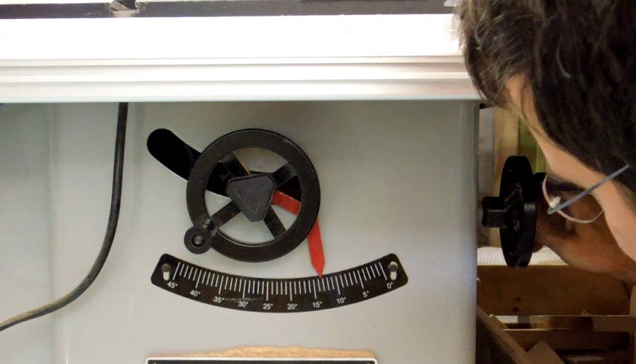
Setting the bevel angle on the saw. As long as the end of the pointer starts at zero and
exactly follows the arc of the scale, these large scales are also quite trustworthy.
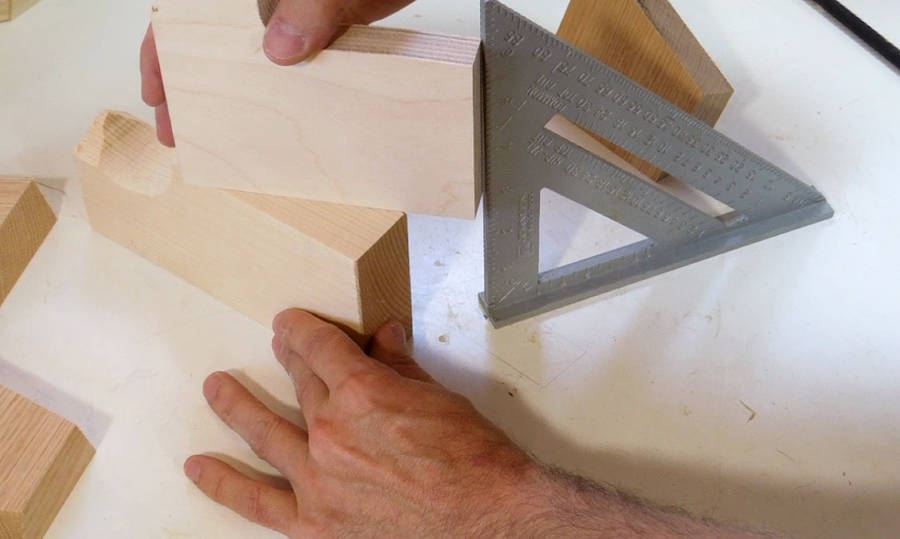
But if you want to second guess and check, a good way to get accurate angles is to use
one of those rafter gauge type squares to set a bevel gauge. The rafter square is one piece,
with a large angle scale, so there's little to go wrong.
Just push the bevel gauge against the inside corner and set it to the scale on the long
edge.
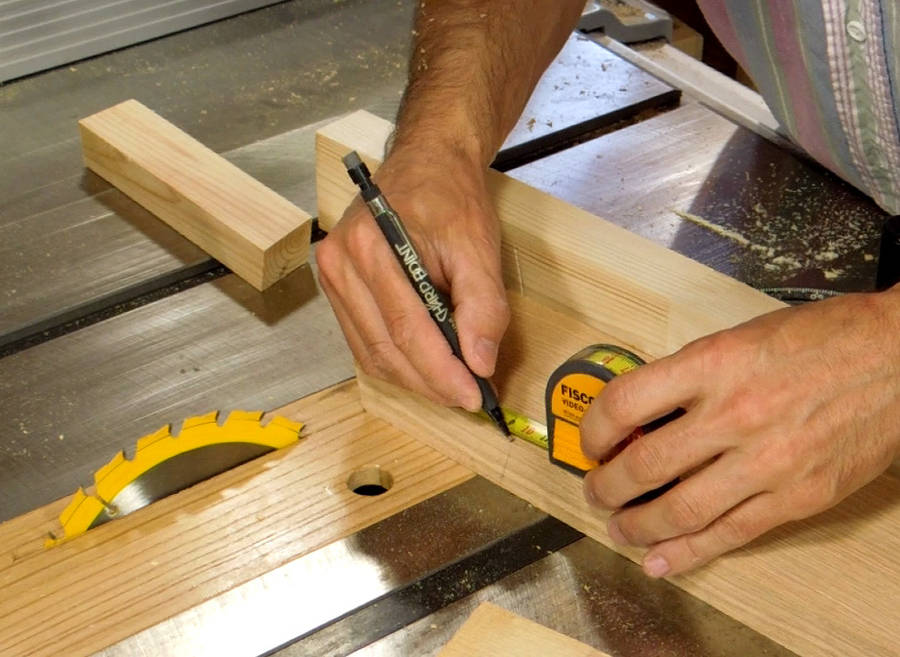
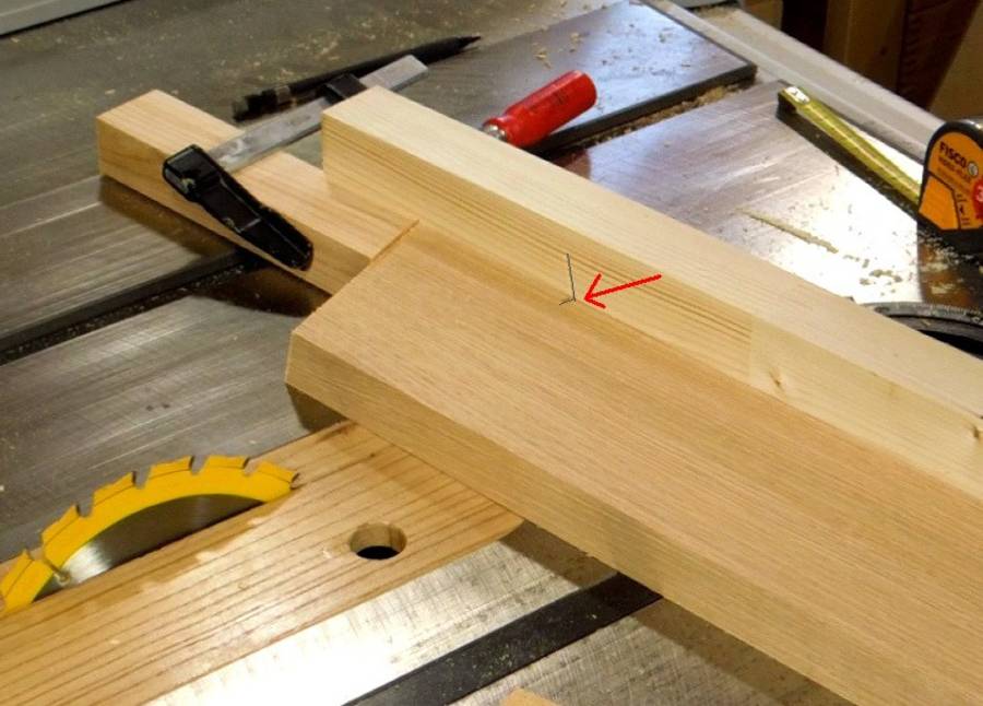
I wanted this 10-sided shape to have a diameter of 30 cm (flat to flat),
and using my table, I had worked out that the longest edge on the pieces needs to
be 9.7 cm long. Here's measuring the first piece.
Now flipping it over, transferring my mark to the other side, and lining it up with the kerf in my
sacrificial fence. I clamped a stop to the fence so I could just push subsequent workpieces
up against it.
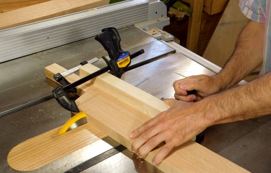
Cutting the pieces. I used a quick grip clamp to clamp the workpiece against the fence.
Although, in retrospect, that caused the workpiece to rock up slightly, which may have
contributed to some inaccuracy.
Next challenge: how to glue the pieces end to end. This is tricky for miter joints, and even
more tricky for these angled miter joints!
Ideally, I'd like to apply a clamping force that is centered on the area of the joint.
Many people prefer to clamp joints like this by applying tape to the outside, but
it's impossible to get good clamping force with tape. I want to make sure these
are good and solid joints.
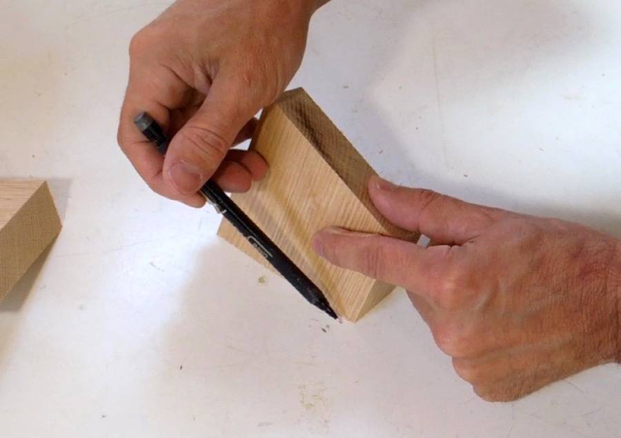
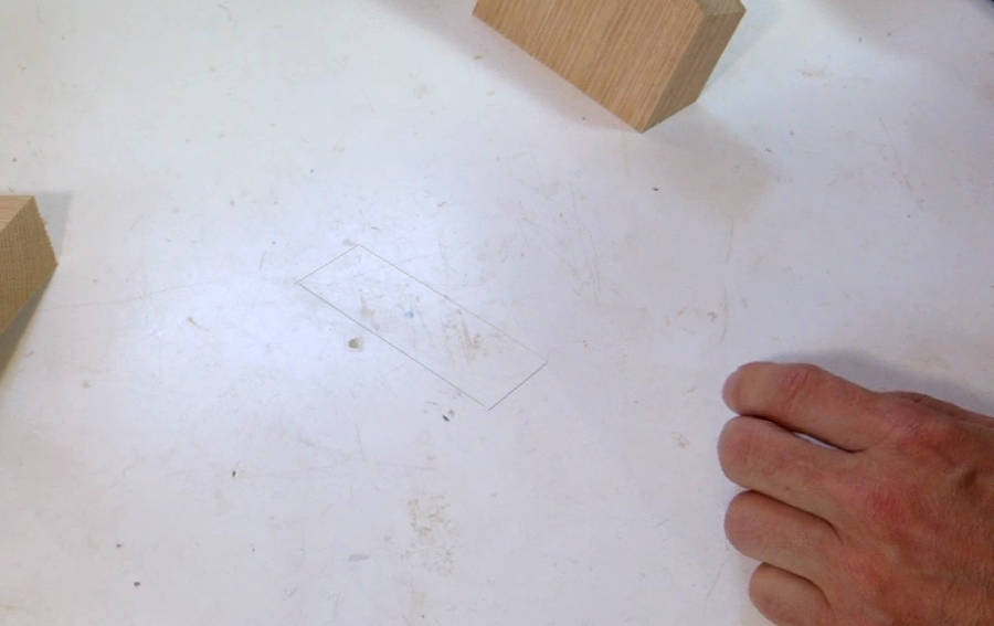
So I start by sketching the outline of the joint on my workbench.
Outline and center marked.
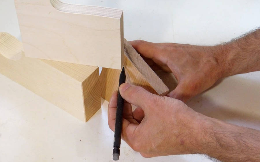
Now using a square and some blocks of wood to "mark" a line perpendicular
to that center point in space above the workbench surface.
With the workpiece put back in place, I can see where the center
of clamping force needs to go.
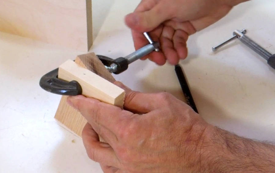
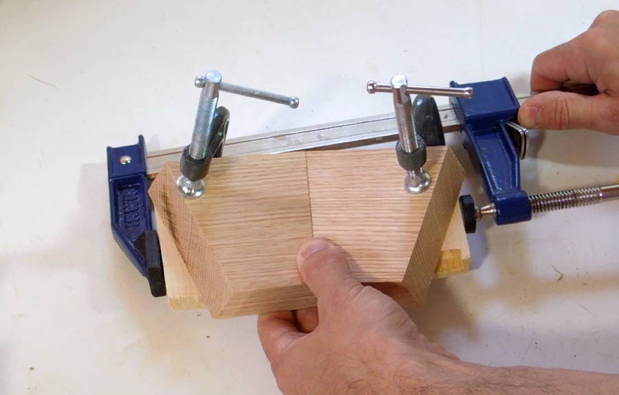
A bevelled piece of scrap wood, clamped to the workpiece, provides a place to apply
the clamp.
What bevel angle to cut on the scrap piece? Exactly the same angle as the joint, so I just
ripped some scrap wood with the angle that I already had set from cutting the
workpieces.
With two scrap pieces clamped to the work pieces, a clamp can now push them together.
This photo makes it look too easy. It's actually quite fiddly getting these
together. One of those one-handed quick-grip clamps makes it much easier, but, unfortunately,
these quick grip clamps can't apply very much force, so I don't consider them suitable
for glueups.
A piece of tape applied to the outside of the joint would probably have made
it easier to keep it aligned, but I'm not used to working with tape in the
workshop, so I didn't think of it at the time.
Here's another view of the clamp applied.
The joint is a simple butt joint. When I did my
glue experiments, I found that a
well glued butt joint can be surprisingly strong. Butt joints need a lot
of glue though, because the end-grain really soaks it in.
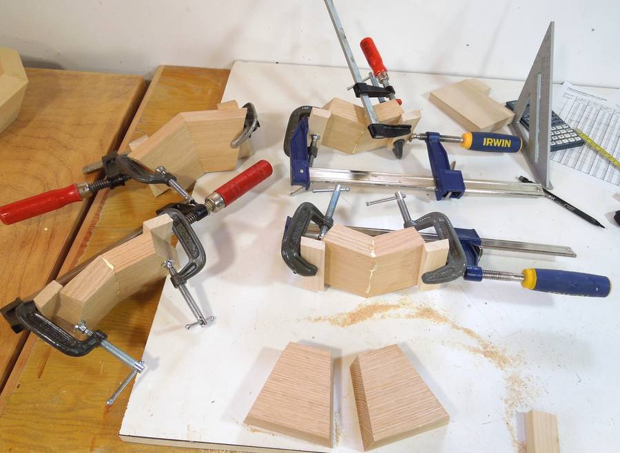
Four pairs of two glued up. I was about to glue the fifth pair of two when I realized --
oops, that would not be a good idea. I want to glue the pieces to two halves, then joint
the halves, so I need to end up with two parts of five segments each.
So I made two segments of three by using the same clamping technique to add
another piece to a segment of two...
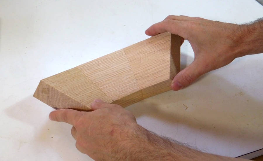
... and then jointed a two and a three segment to make halves of five pieces.
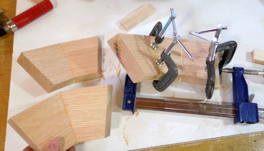
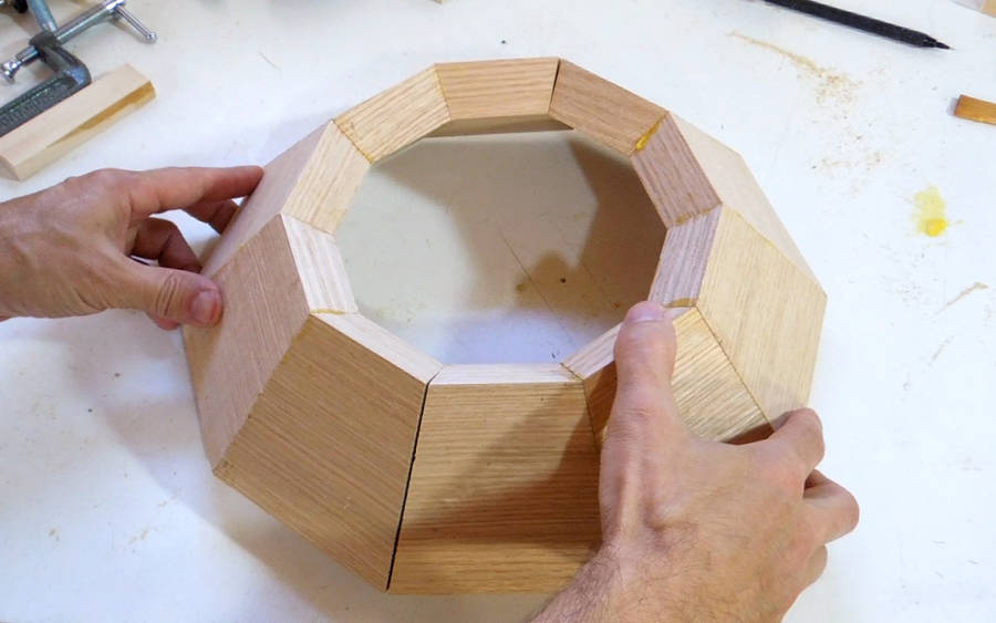
With two halves of five pieces each glued together, the result aligns fairly closely,
but definitely not an exact fit!
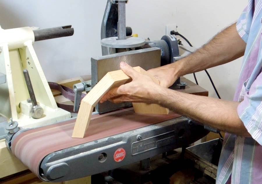
With ten miter cuts on each half, any angle error in the miter joints will add
up ten times at the gap! So I wasn't expecting to
get this perfect, although I had hoped for better. My workpieces tended to lift up
off the table saw when I clamped them to the fence. That may have added some error.
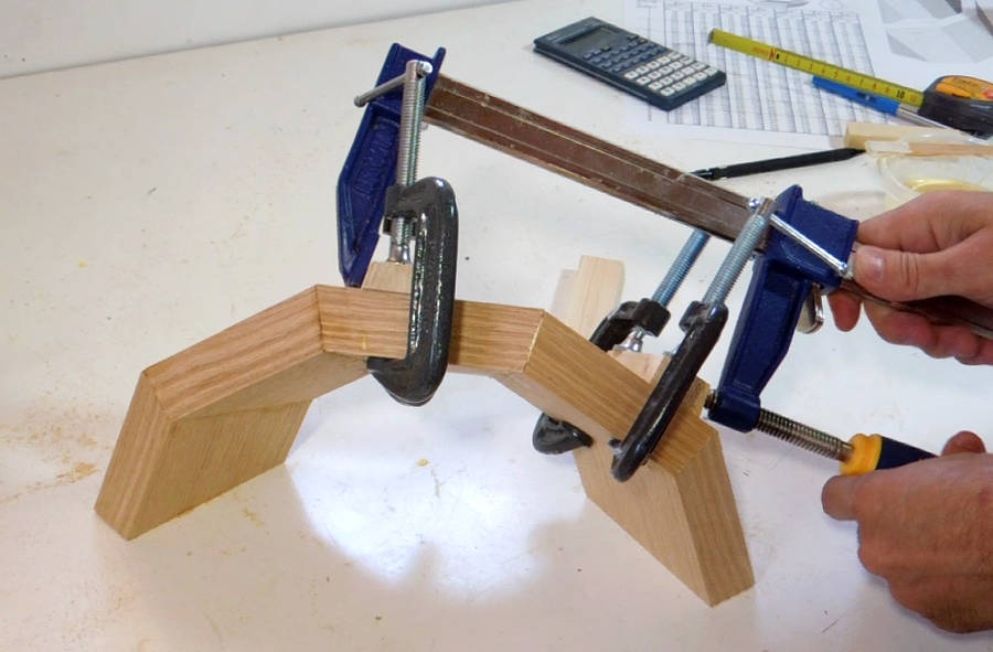
But - no problem! I just put the halves on my belt sander until the two faces
for each piece were in one plane with each other.
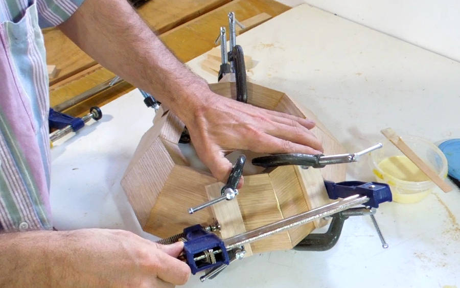
By clamping the joints one joint at a time, all the error accumulated to
just two joints. Had I clamped it together using rubber bands or tape,
the error would have resulted in small gaps in random places instead.
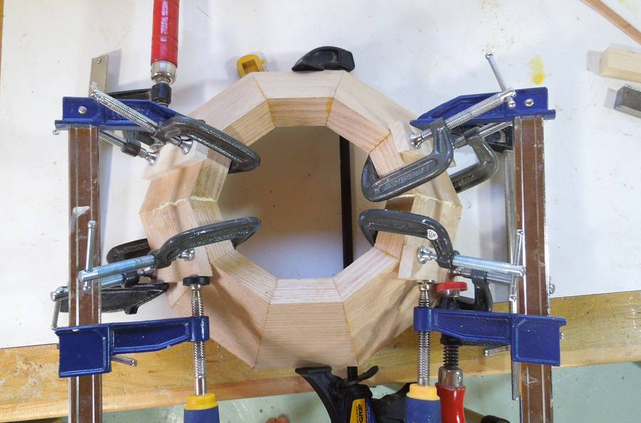
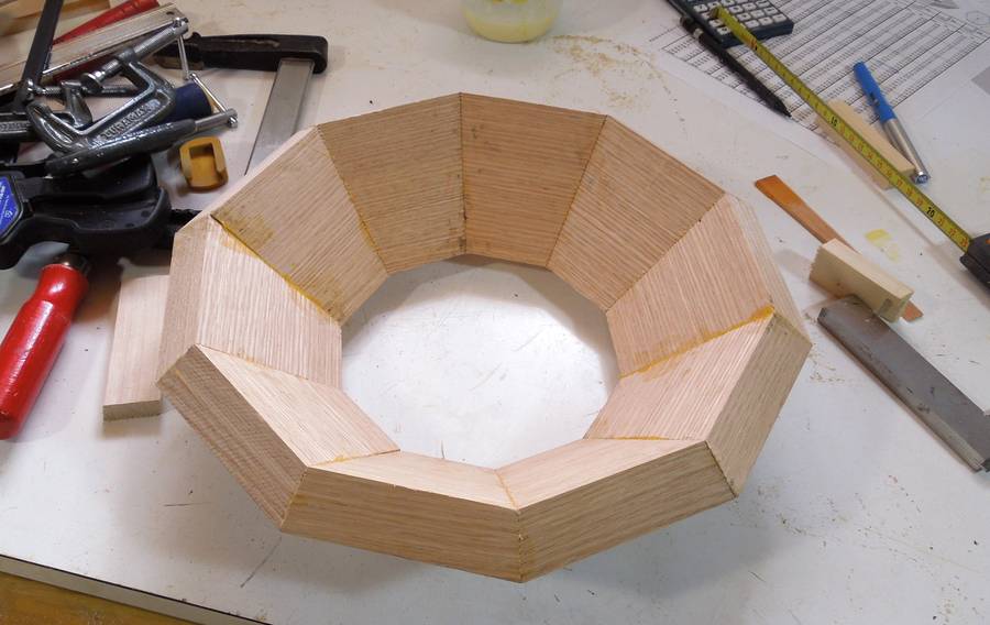
Now the halves fit perfectly!
Same method again with the beveled pieces of scrap to clamp to. But getting it to
align is a tricky thing to do. You may want to curse a bit when you do this.
Not that cursing helps any, but maybe it makes you feel better :)
 A friend, Joel, recently asked me about how to calculate the miters for making
a sort of tapered cylinder out of wood segments. For example, for a straight
eight sided cylinder, the pieces need to be bevelled at 22.5 degrees.
But when the cylinder is tapered, that same 22.5 degree bevel leaves gaps on the inside.
A friend, Joel, recently asked me about how to calculate the miters for making
a sort of tapered cylinder out of wood segments. For example, for a straight
eight sided cylinder, the pieces need to be bevelled at 22.5 degrees.
But when the cylinder is tapered, that same 22.5 degree bevel leaves gaps on the inside.


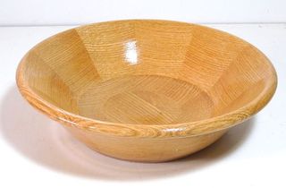 Turning a segmented bowl
 Making a bevel gague
 60-sided geodesic
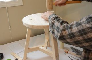 Building a 3-legged stool
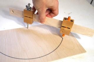 Trammel points compass
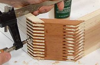 Octagonal box joined box
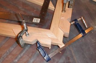 Gluing picture frame
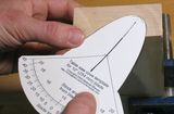 Asymmetric cove cutting
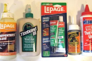 Testing glue types