When I did my pantorouter comparison
with the all-metal version that Kuldeep builds,
I mentioned that I liked how Kuldeep made the followers with a bearing on a shaft,
but didn't have a way to attach a bearing myself, so I'm keeping with the old system
of mounting follower bearings on my wooden pantorouter.
I received many suggestions, such as using Locktite to mount the bearing on the shaft.
But my real problem is actually that shaft size and bearing holes in the bearings I
have don't match. But with so many suggestions, I started thinking about how to make
round followers on shafts for my pantorouter.
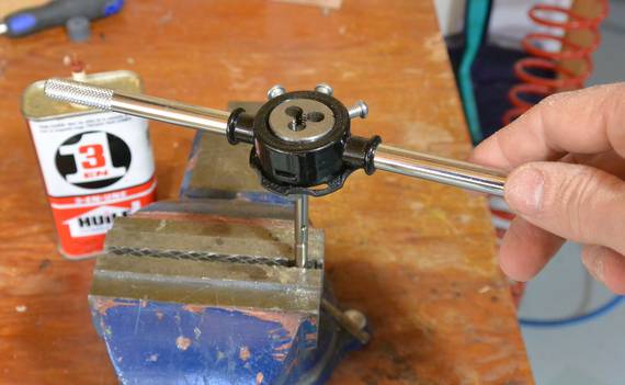
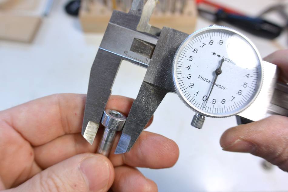
If I cut a thread on the end of the shaft, I could then mount various nuts on it,
like this knock down nut with a nice wide circular flange, so it already forms
a round follower. You can buy nuts like that at The Home Depot.
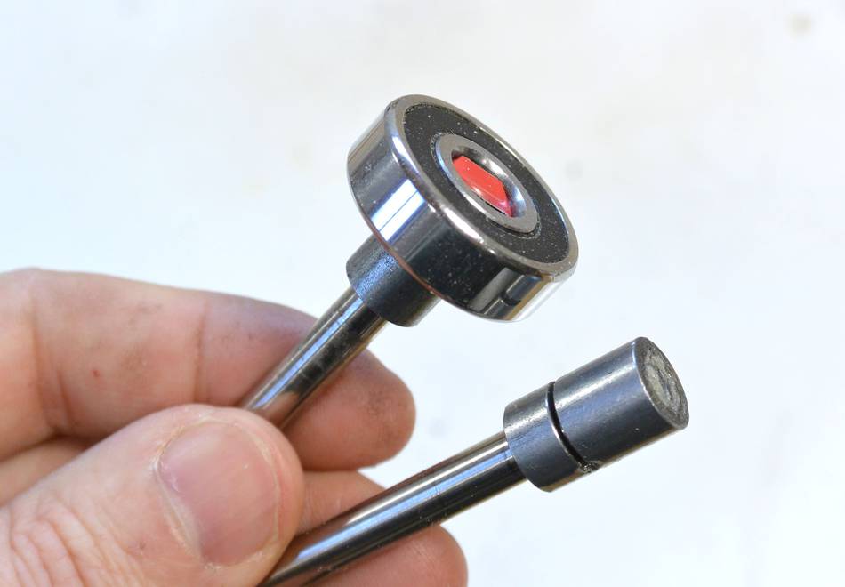
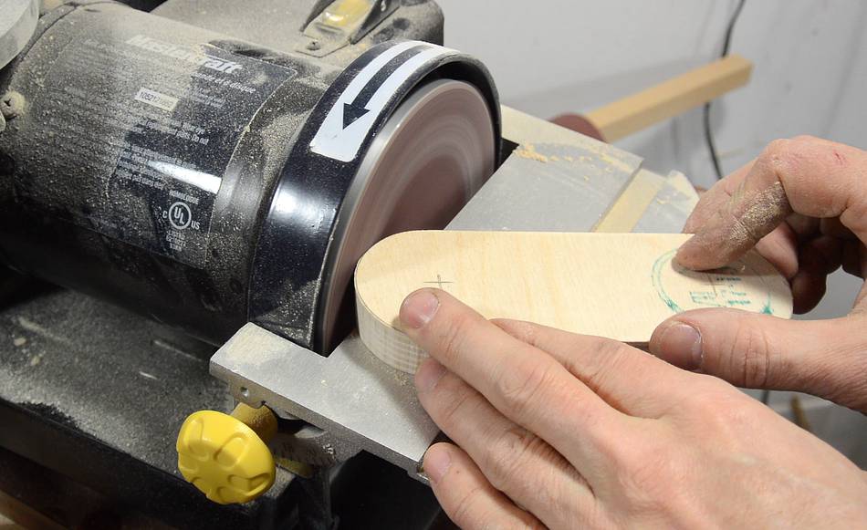
Or I could put a hex nut on the end of the shaft and grind that round
on my bench grinder. With a bit of sanding and polishing, that makes for a fairly
easily sliding round follower, and it turned out quite precise too.
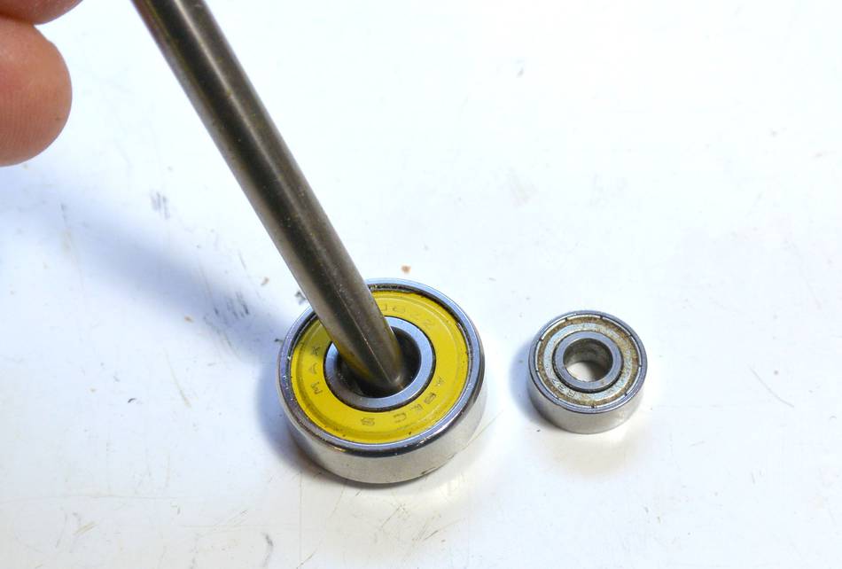
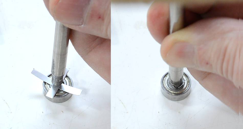
1/2" bearings have smaller holes in them, but using the same technique on the bench grinder
I was able to grind the shaft down so it fit in the bearing, though not tightly. But some shims,
cut from aluminium cans, made for a tight fit.
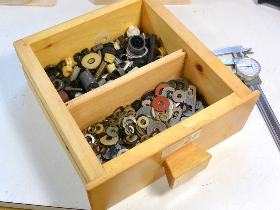
Whenever I take something apart, I always keep the washers and other small hardware that
might be useful. So I have a whole drawer full of round bushings and spacers, and I
started to dig through those to see what might work.
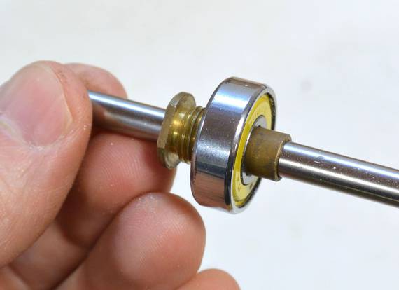
I found some bushings that fit snugly on the 6 mm shafts I was using. I used 6 mm to make
it compatible with Kuldeep's. I used one bushing as a follower directly and ground another one
down a little (again on the bench grinder) to fit the hole of a 26 mm bearing I had. Again,
with a shim from an aluminium can to make it fit snug. I also found one bushing that fit
perfectly between the 6 mm shaft and the 8 mm hole for another bearing.
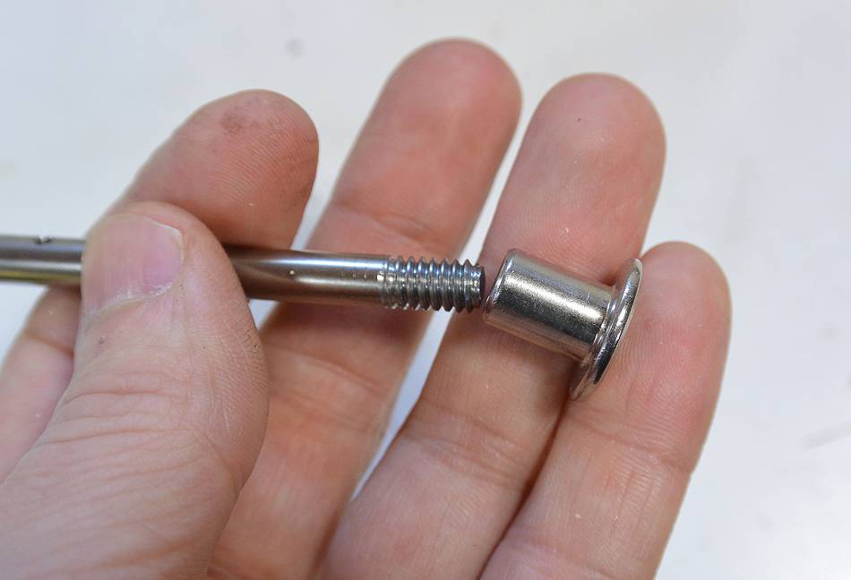
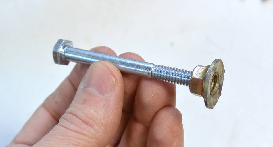
You could also make your followers out of 1/4" bolts, which already have threads on them.
Combined with a nut with integral washer, as shown, all you would have to do is glue the nut on
and cut off the bolt head to make a follower.
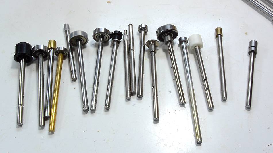
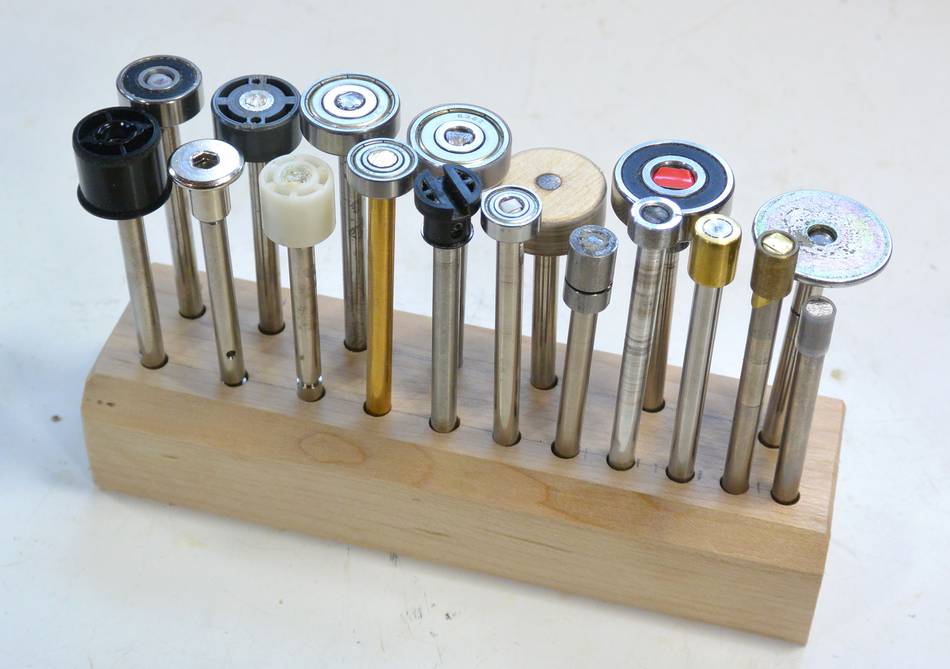
Going through my junk, I made quite a lot of followers of different sizes.
But one size I didn't have was 1" (25.4 mm), so I decided to make one that size
out of wood.
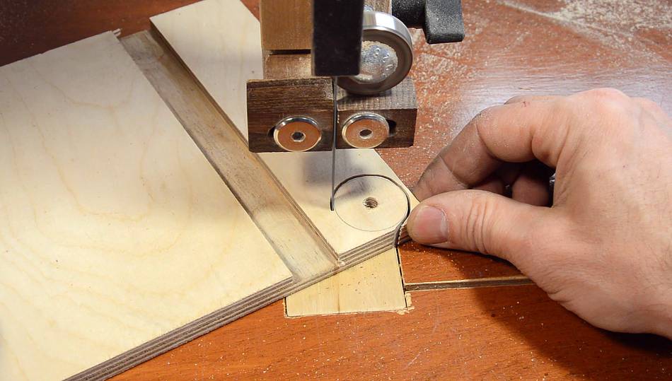
I started by cutting a slightly larger circle from Baltic birch plywood on the bandsaw.
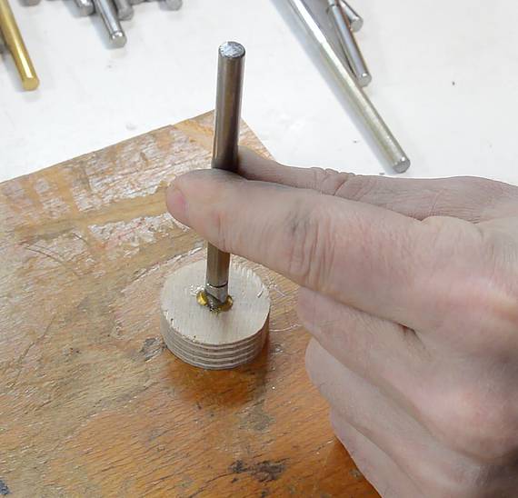
The hole I drilled is a bit undersized for the shaft. I roughened up the end of the shaft
and used some Gorilla glue in the hole and shaft, then drove the shaft in with a hammer.
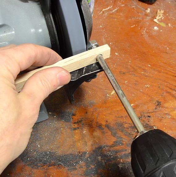
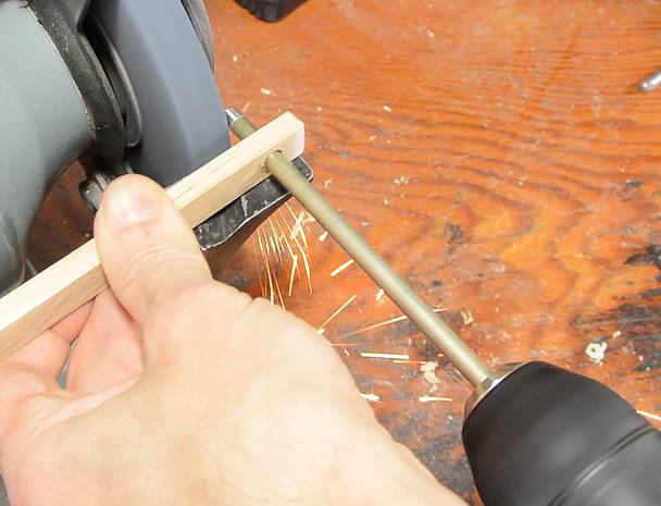
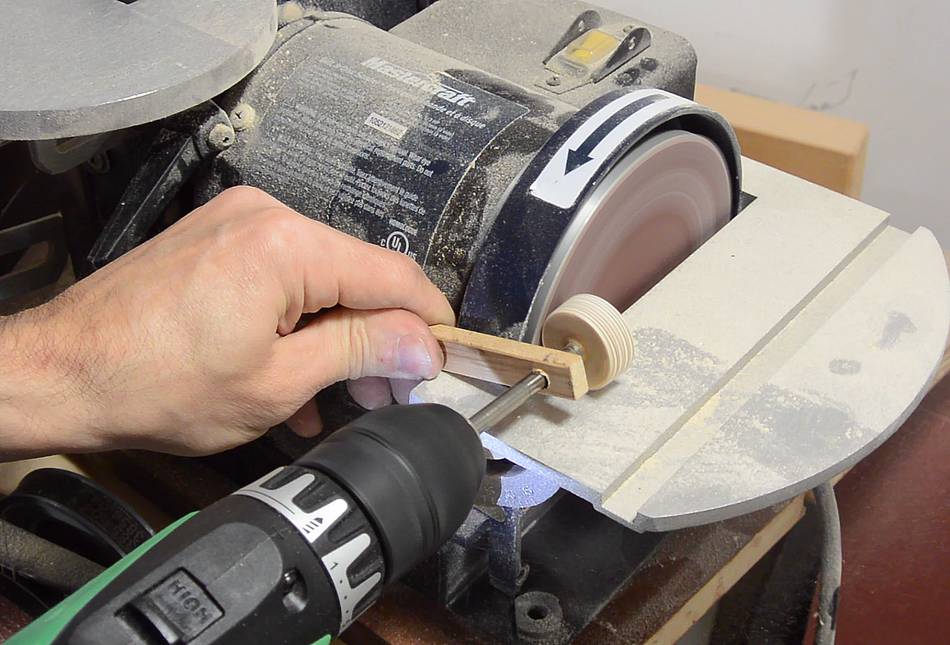
After that, I spun the disk in a hand drill, held up to my disk sander to make it perfectly round.
I'm guiding the shaft with a piece of wood, near the end to make sure it's steady.
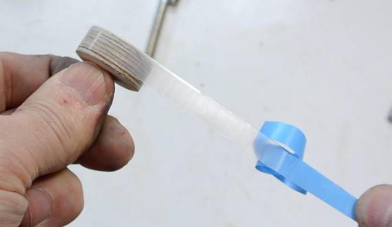
I ended up sanding that one down to just under 1", then applied some UHMW tape to it to
bring it back up to size and make it slide easier.
UHMW tape is also useful for up-sizing metal followers. Each turn of UHMW tape adds 0.3 mm
to the diameter of the follower. Just be sure to have a whole number of turns on the follower so
the tape is the same thickness all around.
I ended up making a lot of followers, mostly from random bushings and round plastic parts.
I have no more than 1 mm of size difference between most of them.
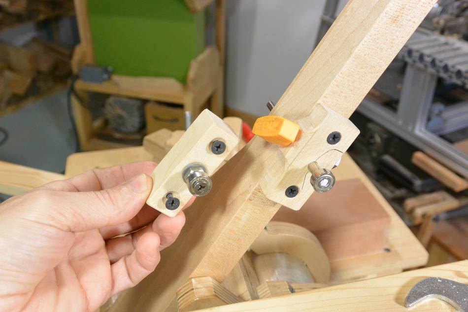
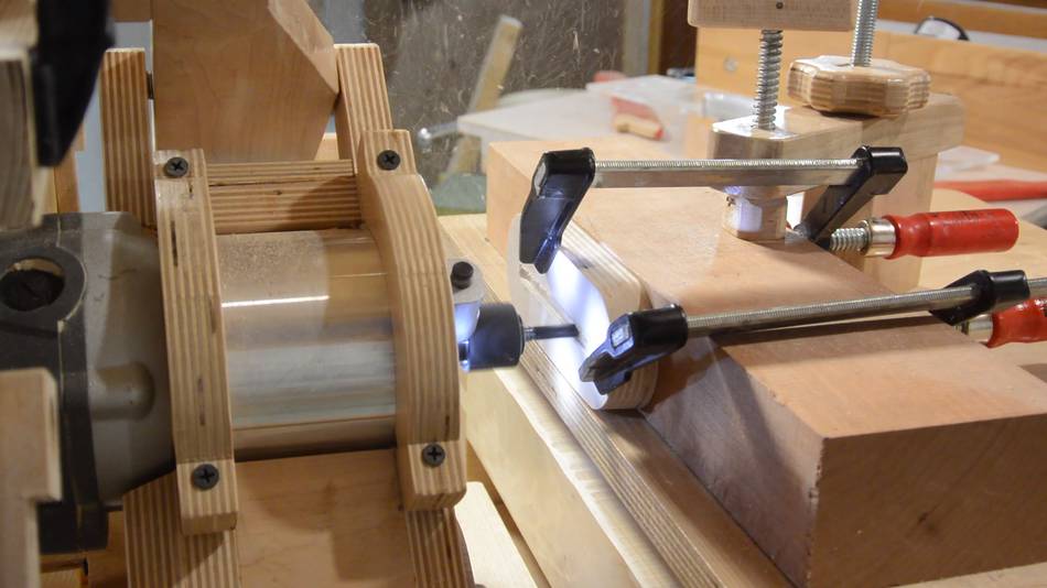
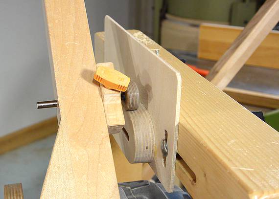
I made a mounting block to clamp the 6 mm shaft on my pantorouter. I didn't have a 6 mm drill,
but a 15/64" drill made for a hole that fit the 6 mm shaft just snugly. The only change I had
to make to my wooden pantorouter was to drill a 17/64" (6.7 mm) hole all the way through the
operating lever, then mount the new holder. The orange knob on the holder clamps the block
together to lock the 6 mm shaft in it. That knob came from a broken Ryobi circular saw.
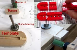
Making tapered and slotted tenon templates
Having figured out how to make followers like on the
all metal pantorouter, the next challenge
was to make the clever templates with the slot in the middle and tapered edges around
the outside. The tapered edges of the tenon template allow fine adjustments in
tenon size to be made.
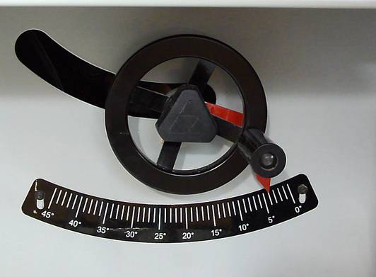
I set my table saw to four degrees, then cut a bevel on a piece of 18 mm thick
Baltic birch plywood. 18 mm is perhaps a bit thick, but I figured more thickness is better,
and the next thinnest Baltic birch plywood I had was 11 mm.
With the wide side of the plywood facing up, I set my compass to half the width, then
use it with the point on either edge to check the center of the mark, and draw an arc
from there.
I tilted the bandsaw to four degrees, checking it with a speed square, because my
homemade bandsaw doesn't have any angle
scale.
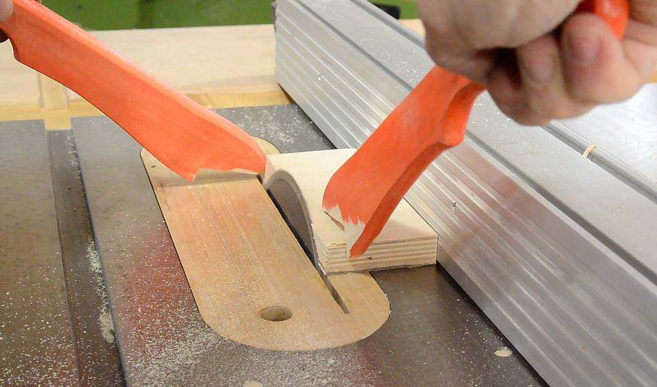
Cutting out the semicircles. I cut within half a millimeter to the line...
...so that I don't have to sand away very much material finishing it up.
For my first tapered template, I drew the semicircles on the front (the narrow side),
but then realized the disk sander table doesn't tilt towards the disk. Oops! That's why
I drew the semicircles on the back this time. I was however able to tilt the strip
sander table towards the belt a bit, but the disk sander is better for this job.
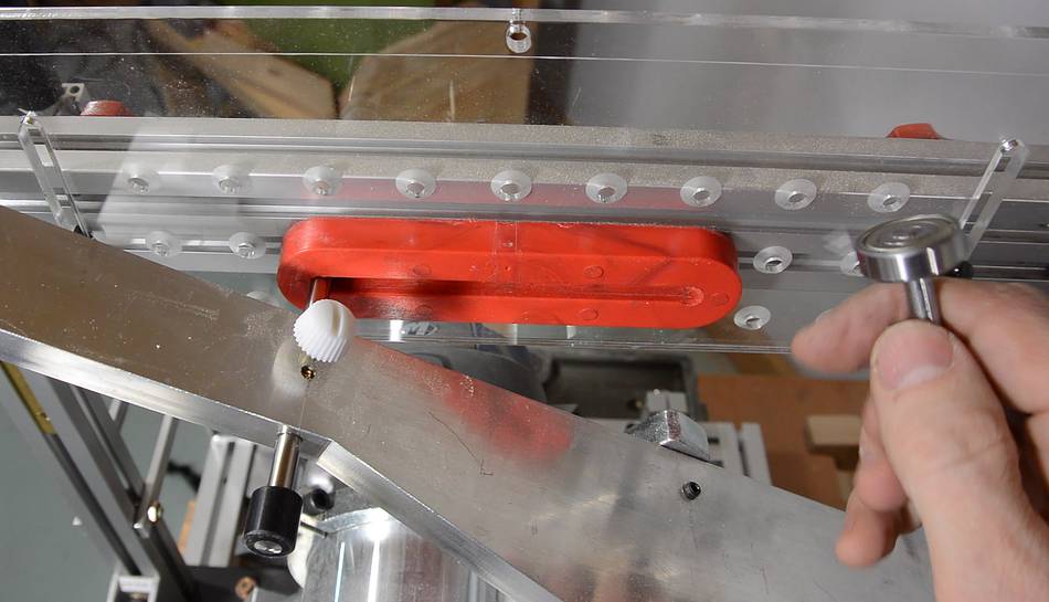
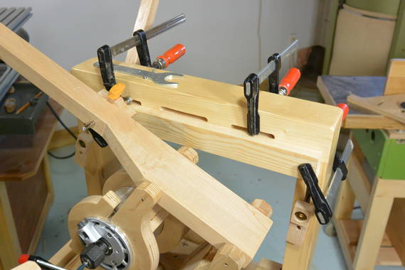
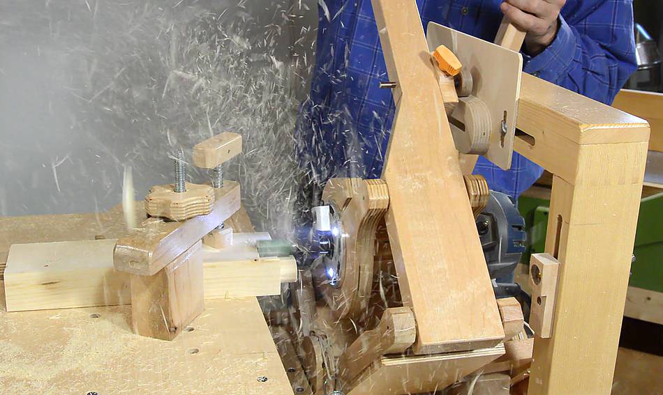
I cut the slot in the template on my pantorouter, just using a straight piece of wood to roll
the follower bearing along to get the straight line.
Despite being very careful, I got the line about 1 mm off center and, worse yet, about
0.2 mm higher on one side. Arrgh! Sliding the template on a router table to cut the slot
could be iffy, but would avoid the possibility of getting the angle wrong. I ended up "fixing" it
by doing a plunge cut on the table saw (with the template held down against the fence),
then finishing it with a chisel.
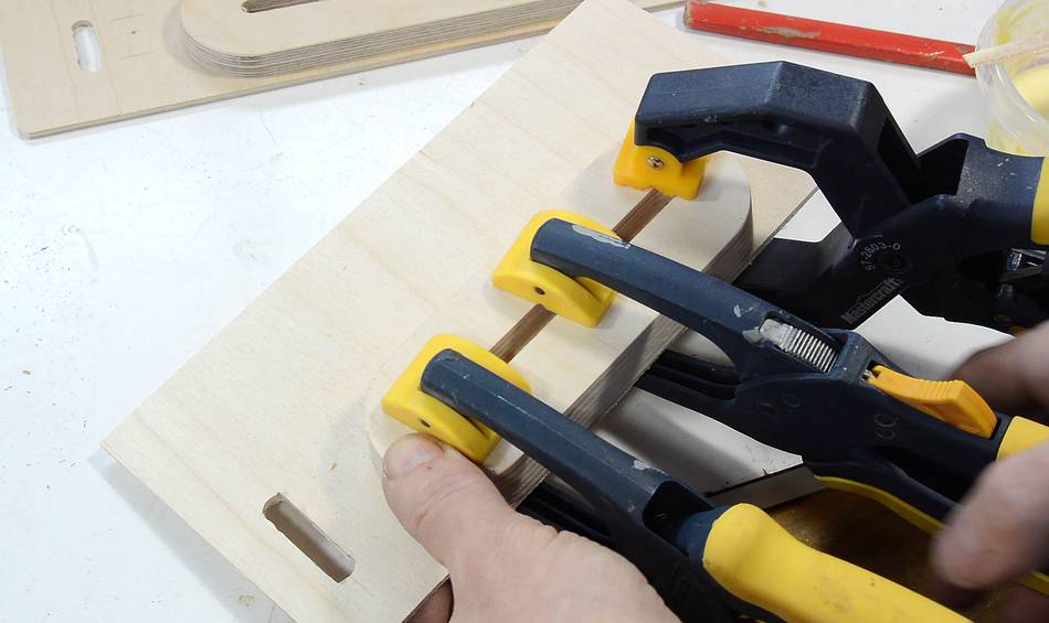
Gluing the template on a backer board, being very careful to keep the template
exactly flush along the bottom edge to make sure it's straight.
So I hope this gives you some ideas for how to make followers and tapered
templates for a wooden pantorouter.
I had originally designed the pantorouter with the follower bearing
mounted to a small block of wood
, but this method of mounting the bearing on the end of a rod
is much better, and I have since changed the plans to reflect using this method.
 When I did my pantorouter comparison
with the all-metal version that Kuldeep builds,
I mentioned that I liked how Kuldeep made the followers with a bearing on a shaft,
but didn't have a way to attach a bearing myself, so I'm keeping with the old system
of mounting follower bearings on my wooden pantorouter.
When I did my pantorouter comparison
with the all-metal version that Kuldeep builds,
I mentioned that I liked how Kuldeep made the followers with a bearing on a shaft,
but didn't have a way to attach a bearing myself, so I'm keeping with the old system
of mounting follower bearings on my wooden pantorouter.


 Making and setting up tenon templates
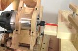 Big mortise and tenons
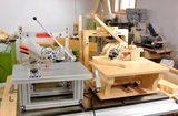 Comparing pantorouters
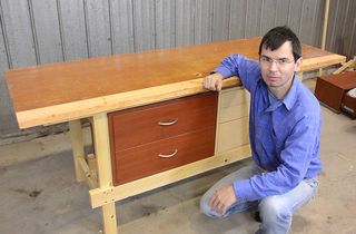 Quickie workbench
 More about
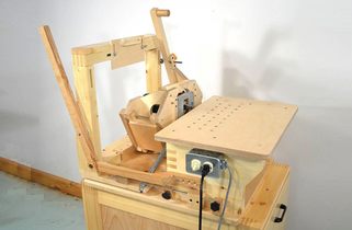 Pantorouter XL
 Tearing down a printer
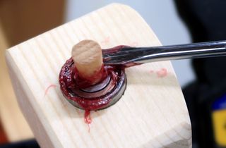 Re-greasing shielded bearings, no disassembly