 Previously the saw had a single pivoting assembly for raising
and lowering the blade. Raising the blade would also
raise the motor (motor removed in this picture).
Previously the saw had a single pivoting assembly for raising
and lowering the blade. Raising the blade would also
raise the motor (motor removed in this picture).
The purpose was incorporating a true riving knife ino my table saw. This was achieved successfully as shown. The design is heavily based on that of the new Delta Unisaw. The secret lies in a parallel linkage arm. This must be located in a parallel to the line from the arbor center to the pivoting center of the raising mechanism. If you inspect the photos carefully you'll see what I mean. The result is a riving knife that travels exactly at 3mm from the blade all along the height range.
This one, in particular, I believe has the merit of addressing a much neglected safety issue.
The Europeans have been using riving knifes for ages and I felt it was time to emulate their concern. Hopefully, my work should prove it is possible to, at least, consider the addition and that putting some work into it the outcome is more than acceptable.
Previously the saw had a single pivoting assembly for raising
and lowering the blade. Raising the blade would also
raise the motor (motor removed in this picture).
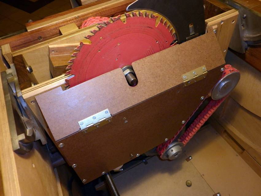
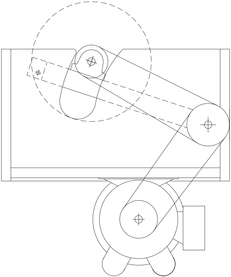 My modified design is inspired by how the SawStop drive train works.
Actually, the SawStop arbor is fixed and the whole unit is raised/lowered along two vertical bars. The saw blade and the riving knife just go for the ride. The advantage is that there is no need for linkage to control the riving knife position.
In my case, the blade arbor platform pivots to raise/lower the blade. By using an intermediate axle, the motor remains in a fixed position and transfers its power to this axle. Since the arbor platform will now pivot with the same center as the intermediate axle, the belt length from this axle to the arbor remains constant.
The final result is that the blade height handwheel will only have to move the arbor platform and NOT the motor. This reduces wear on the yoke nut and should provide a much smoother and easier blade height control.
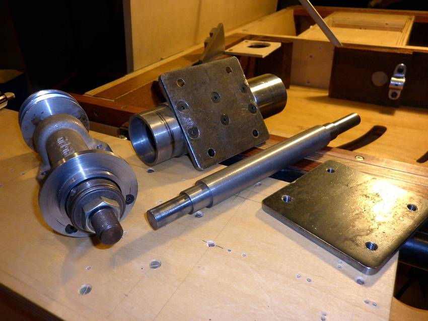 The arbour, jackshaft, and jackshaft mount
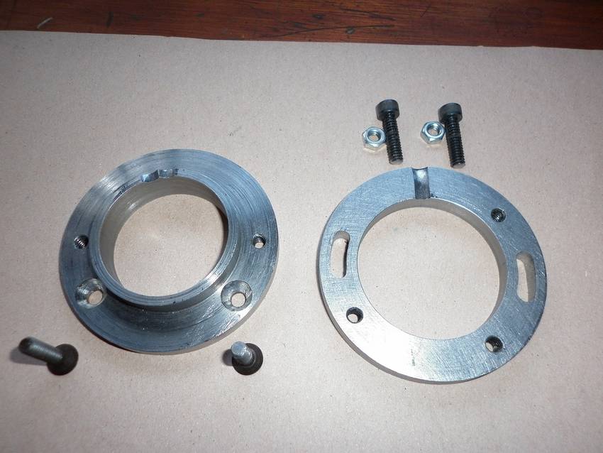 This is the two-part ring where the Riving Knife Arm is mounted. On the left
is the fixed base, which is screwed onto the saw arbor casing. On the right
is the movable ring where Riving Knife Arm is attached.
This is the two-part ring where the Riving Knife Arm is mounted. On the left
is the fixed base, which is screwed onto the saw arbor casing. On the right
is the movable ring where Riving Knife Arm is attached.
 The Riving Knife Arm is in two parts to provide a suitable offset
and simplify assembly.
The Riving Knife Arm is in two parts to provide a suitable offset
and simplify assembly.
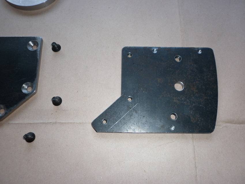
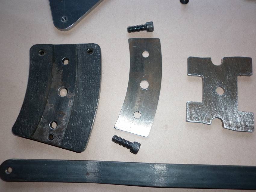 Left to right: Riving Knife Base, Retainer and Pressure Plate.
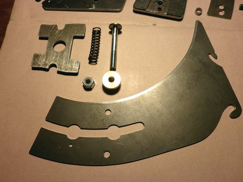
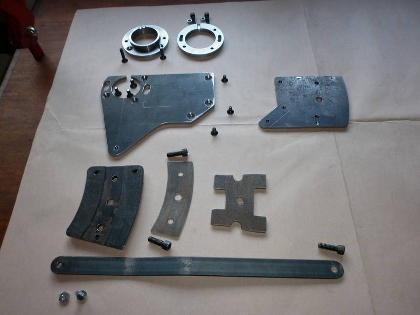 A view of the components. The linkage arm is at the bottom.

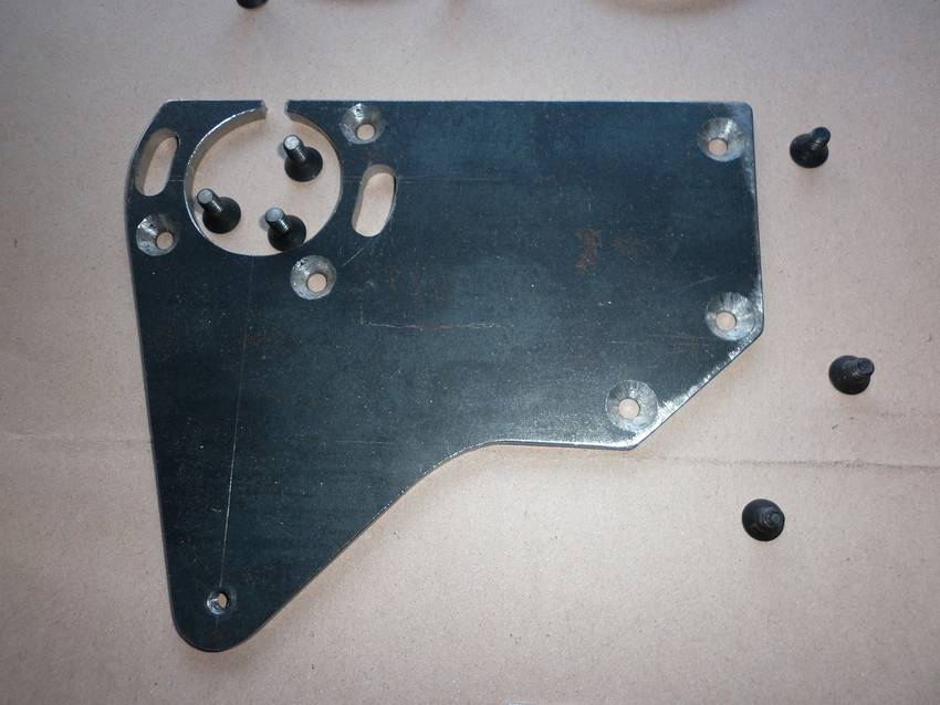
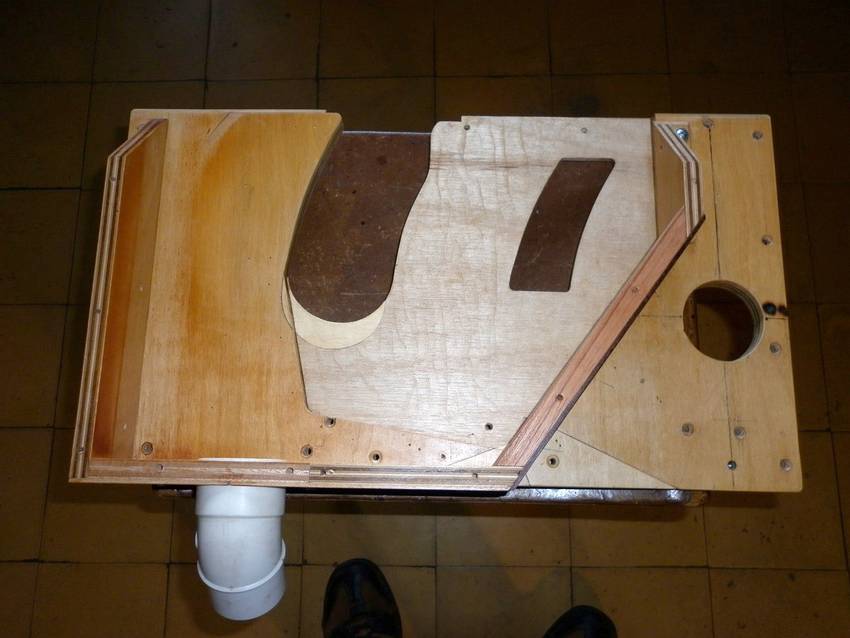 The lighter area is a recess routed to provide clearance for the riving knife
mechanism. The frame is for the dust collection arrangement.
The lighter area is a recess routed to provide clearance for the riving knife
mechanism. The frame is for the dust collection arrangement.
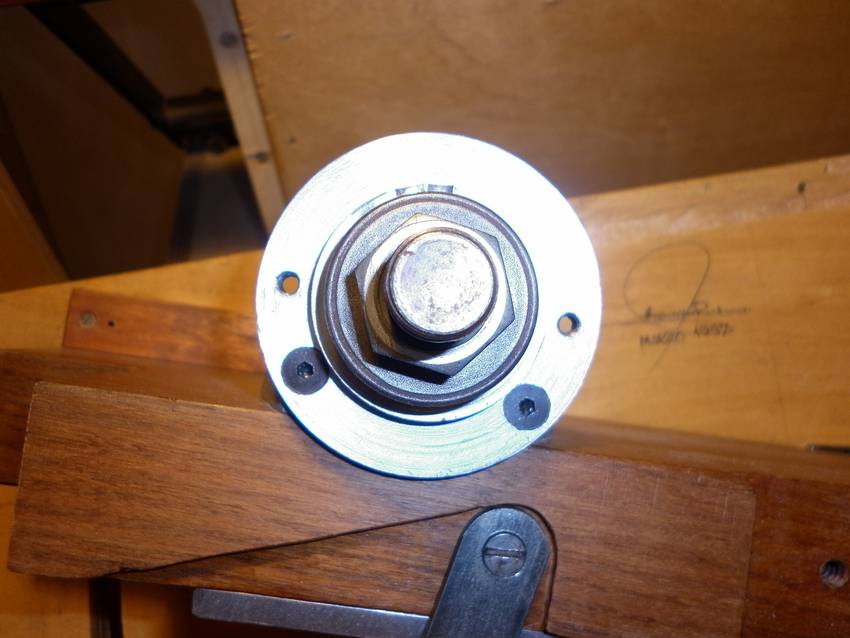
 The ring mounted on the saw arbor.
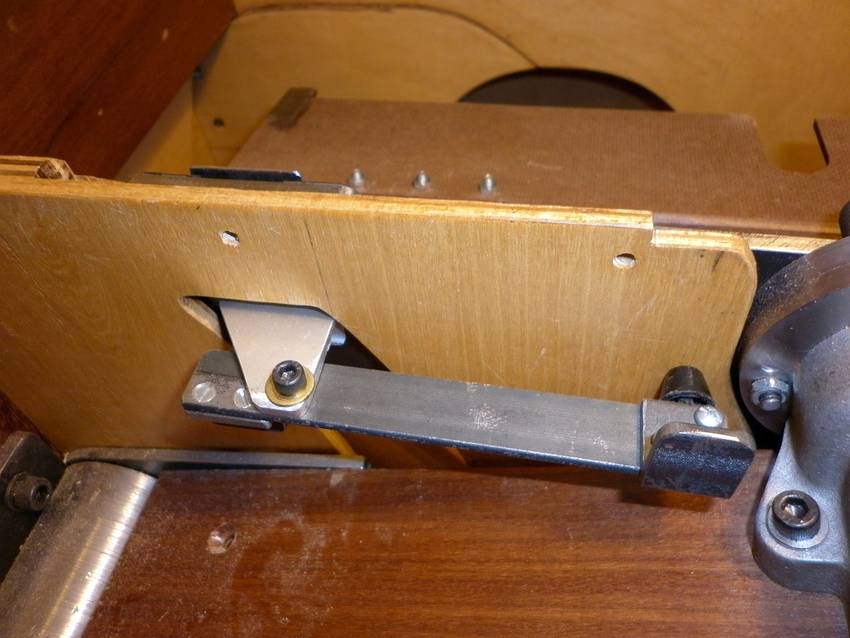
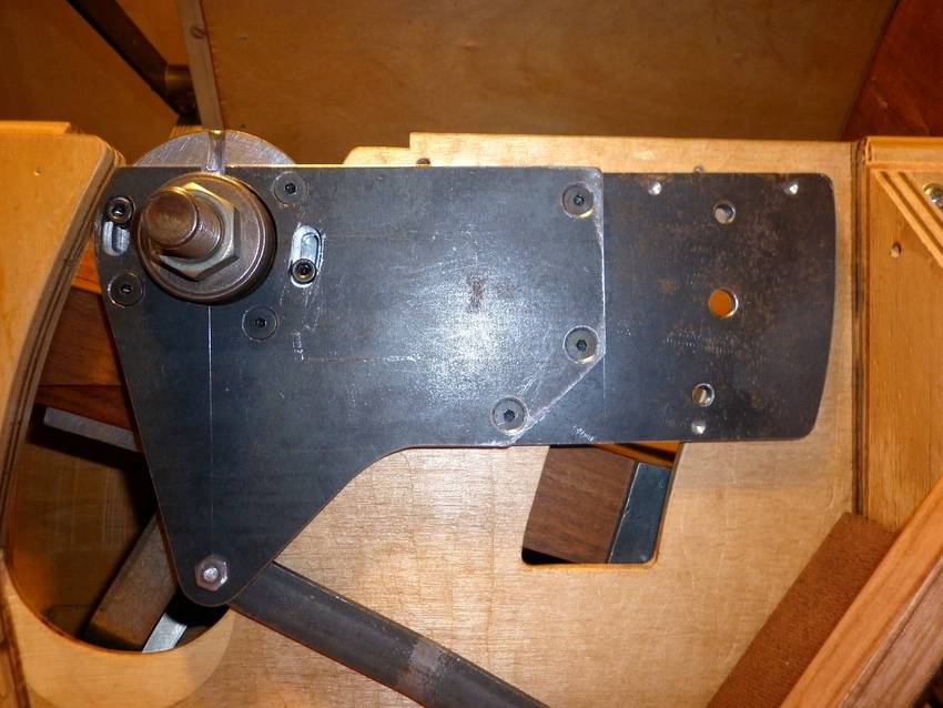 The riving knife Arm mounted in place and the linkage installed.
This is the highest position.
The riving knife Arm mounted in place and the linkage installed.
This is the highest position.
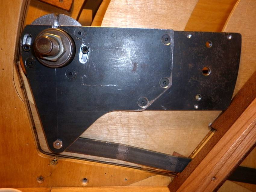 The riving knife Arm in the lowest position.
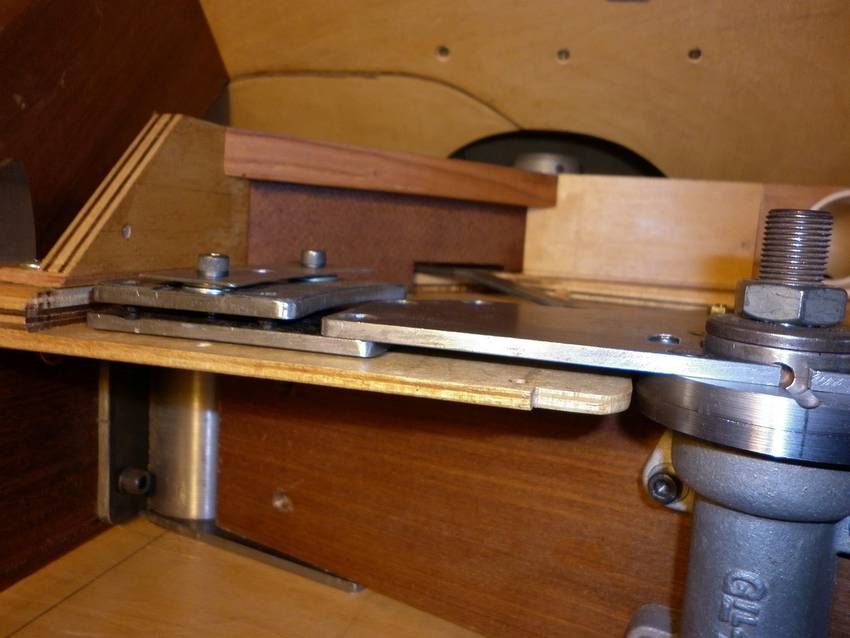 View from above. Notice the offset created with the two part Arm.
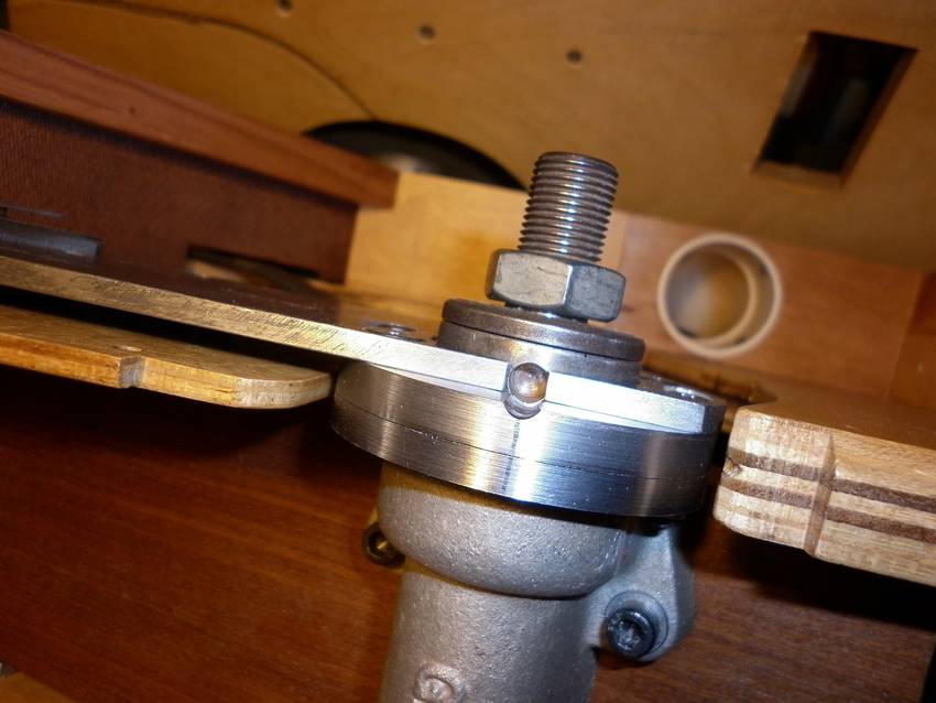 A hole in the arbor can be aligned to receive a 1/4" steel rod. This
locks the arbor for blade changing.
A hole in the arbor can be aligned to receive a 1/4" steel rod. This
locks the arbor for blade changing.
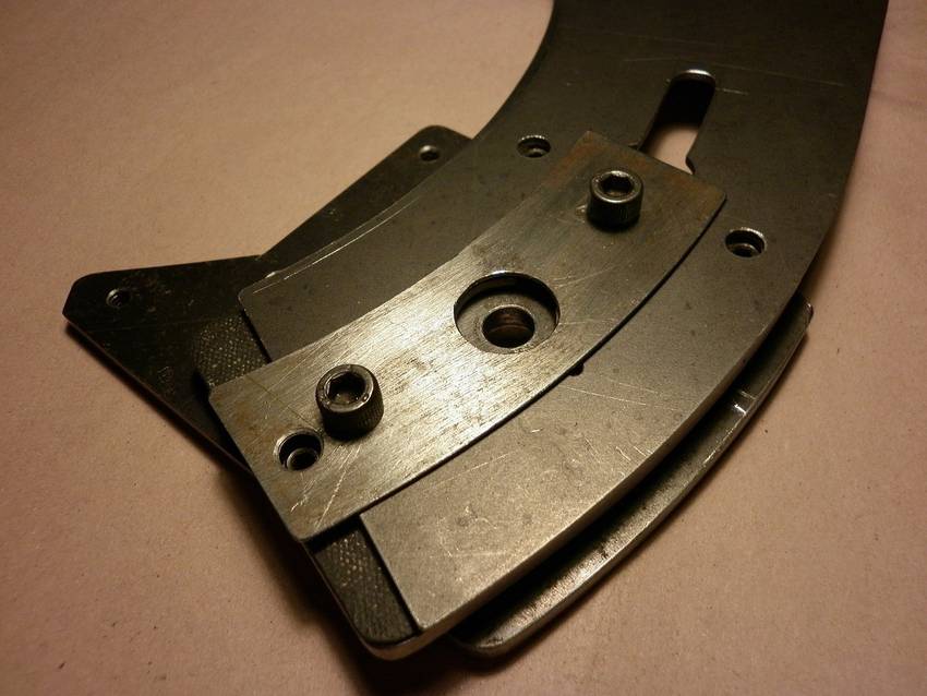
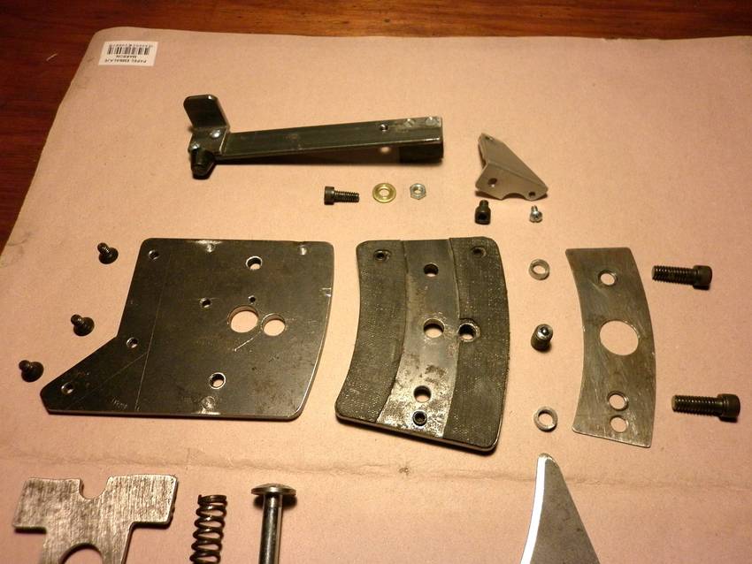 This is the final array of parts before assembly. There are more holes in some
of them. These were necessary to provide for adjustments and proper assembly
procedure.
This is the final array of parts before assembly. There are more holes in some
of them. These were necessary to provide for adjustments and proper assembly
procedure.
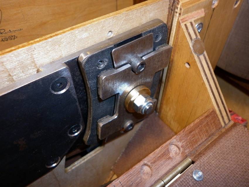
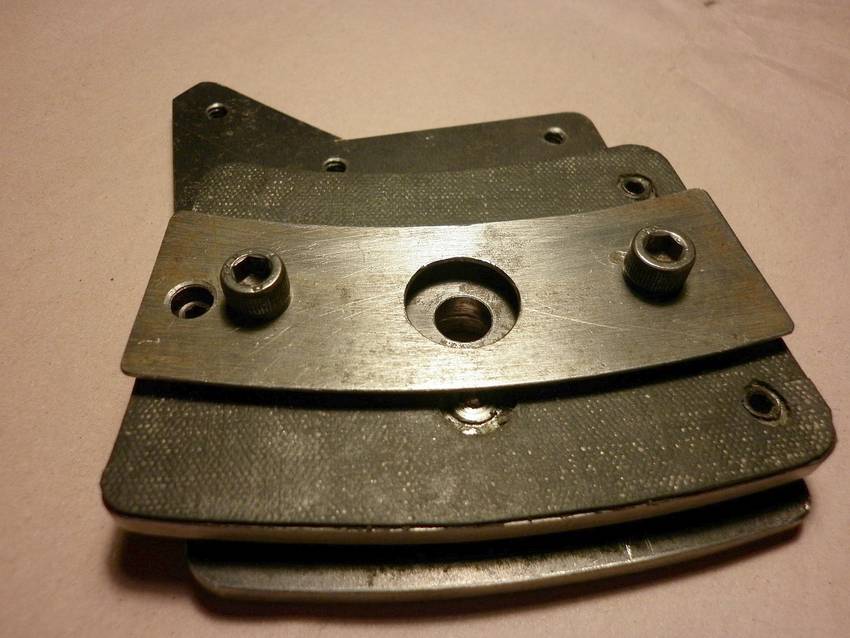 The Arm, Base and Retainer assembled. Loosening the two capscrews the riving
knife can be aligned with the three grub screws. Re-tightening the capscrews
effectively locks the unit securely. There are a couple of spacers under
these to provide just enough clearance for the riving knife under the retainer.
The base is partially covered with 0.8 mm hard rubber strips. The shiny thing
is a (barely visible) spring loaded steel ball to lock the riving knife in the
through cut position. For non-through cuts the riving knife is simply dropped
as far as it goes.
The Arm, Base and Retainer assembled. Loosening the two capscrews the riving
knife can be aligned with the three grub screws. Re-tightening the capscrews
effectively locks the unit securely. There are a couple of spacers under
these to provide just enough clearance for the riving knife under the retainer.
The base is partially covered with 0.8 mm hard rubber strips. The shiny thing
is a (barely visible) spring loaded steel ball to lock the riving knife in the
through cut position. For non-through cuts the riving knife is simply dropped
as far as it goes.
 Showing the riving knife in the through cut position, which is also the correct
one for riving knife alignment.
Showing the riving knife in the through cut position, which is also the correct
one for riving knife alignment.
 The actuating arm. Pulling to the left side loosens the clamp and the riving
knife may be moved to either of two positions or completely removed.
The actuating arm. Pulling to the left side loosens the clamp and the riving
knife may be moved to either of two positions or completely removed.
 The brass button and lock-nut are mounted on a 5/16" spring loaded screw.
The actuating arm pushes on the screw head and loosens the clamp. The clamp
is also rubber lined with the same material used on the base.
The brass button and lock-nut are mounted on a 5/16" spring loaded screw.
The actuating arm pushes on the screw head and loosens the clamp. The clamp
is also rubber lined with the same material used on the base.
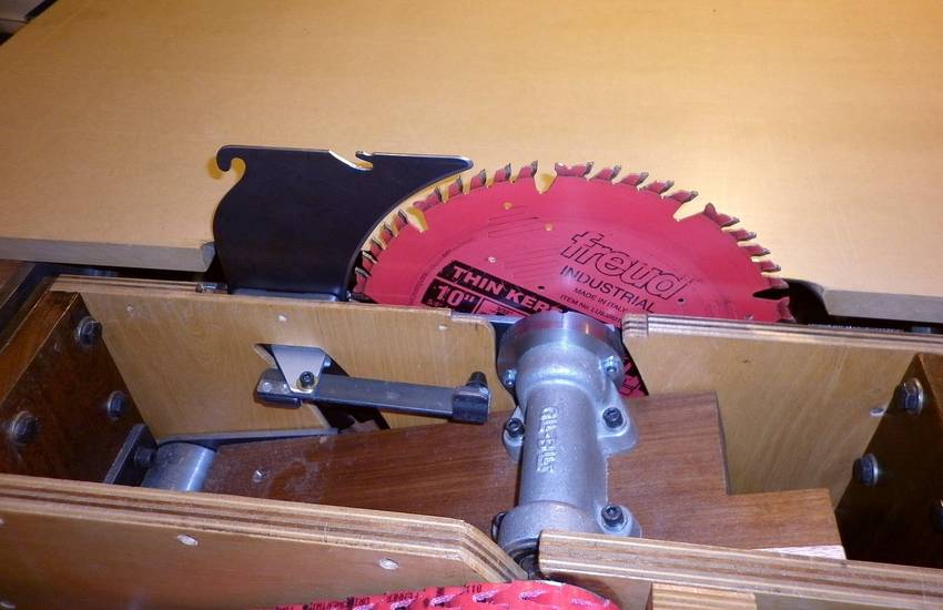
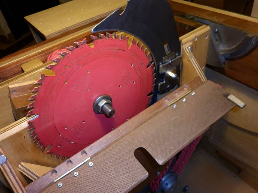 The saw blade in place. Note the dust baffle, which pivots out of the way for
blade mounting.
The saw blade in place. Note the dust baffle, which pivots out of the way for
blade mounting.
 The dust-box with the hinged cover closed.
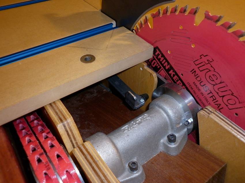 Pushing the sliding table as far as it will go provides ample access to the
actuating arm.
Pushing the sliding table as far as it will go provides ample access to the
actuating arm.
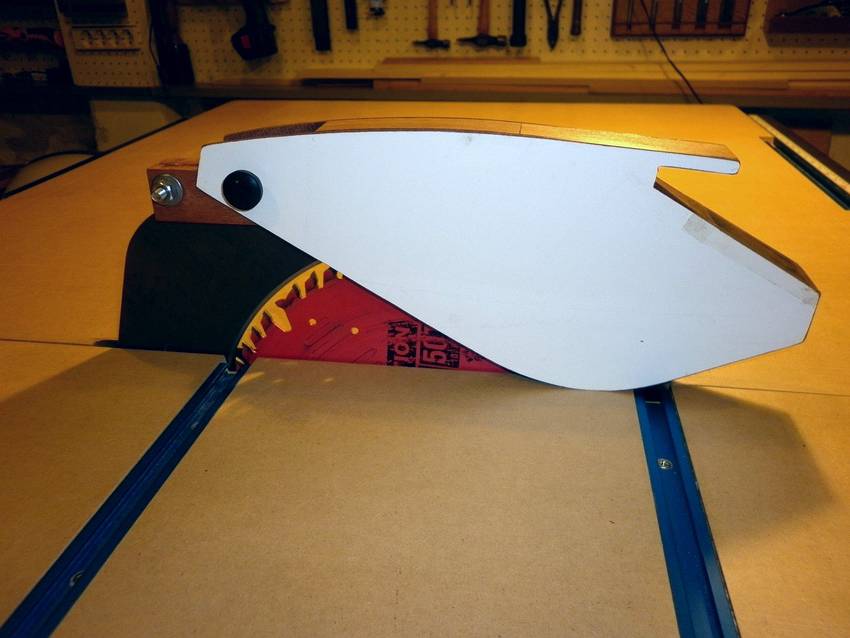 A prototype for a saw guard was cobbled from hardboard and scraps.
After some testing in real situations I intend to rebuild it from
polycarbonate. This will provide a better view of the blade and the
cutting line
A prototype for a saw guard was cobbled from hardboard and scraps.
After some testing in real situations I intend to rebuild it from
polycarbonate. This will provide a better view of the blade and the
cutting line
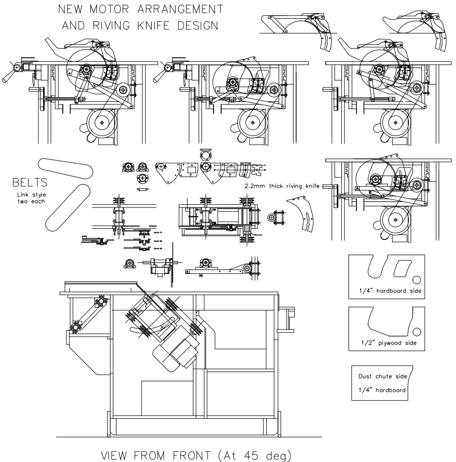 You can download these drawings:
PDF version of table saw drawings
DWG (AutoCAD) version of table saw drawings
Please note that the drawings are 2D plan views, not 3D models.
More of Hector's prjects