Jens Larsen's dial-a-tenon jig
 Jens Larsen, from Denmark writes:
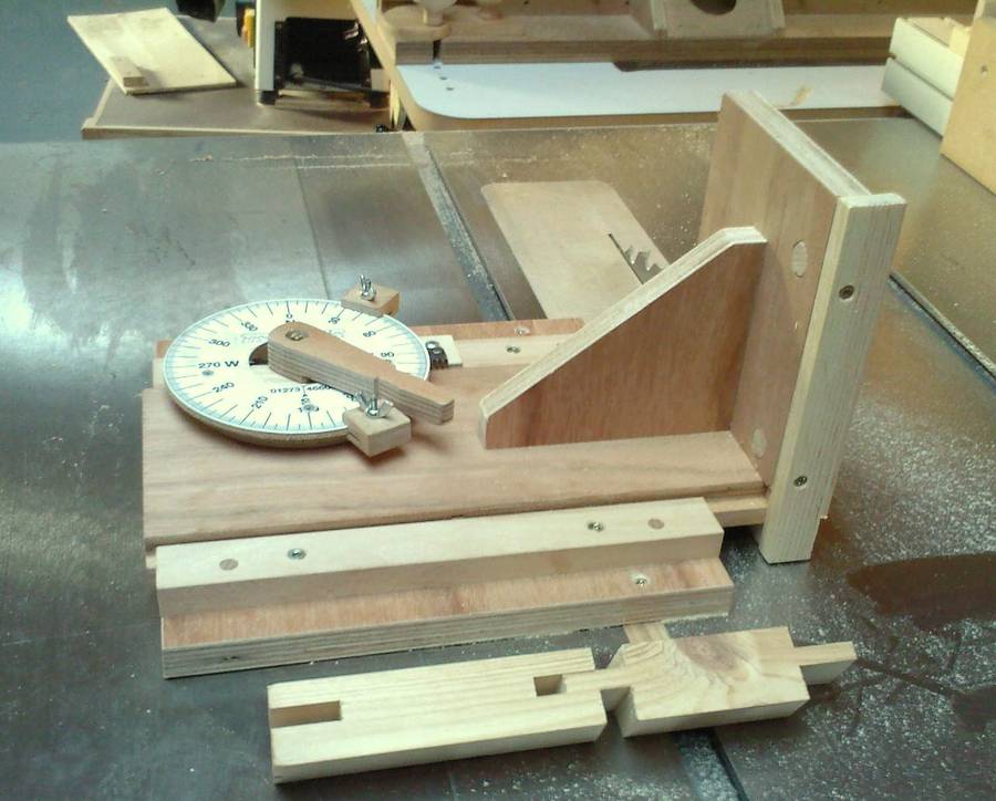
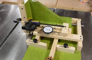
The idea was to make a jig that, like yours, could cut both cheeks in one go, is reasonably accurate, and easy to set and use.
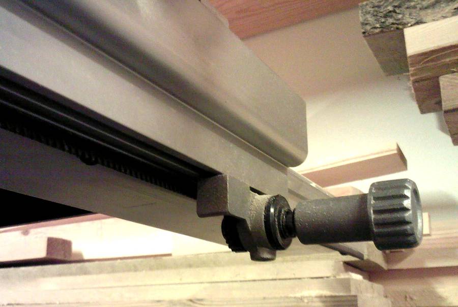 Seeing how well the fine adjustment of the fence of my new table saw
worked, it inspired me to try the same principle with a rack and pinion
on the jig. I also happened to have a set left over from a
previous project (the steering on a kids car).
Seeing how well the fine adjustment of the fence of my new table saw
worked, it inspired me to try the same principle with a rack and pinion
on the jig. I also happened to have a set left over from a
previous project (the steering on a kids car).
Considering that the jig is probably not going to be used that much, wear is not a real issue. With the limited travel, and the small effect a possible racking would have on the accuracy, I decided that carefully made wooden runners would do. Effects of seasonal changes in wood size can be minimized by keeping the dimensions as small as possible.
 The dimension were chosen to give reasonably long guides on
the jig and the sled, room for the dial and stops, and good support
for the workpiece being cut. With this in mind, and the bit of plywood I had
available, I made the base plate 260 x 260 mm, the sled 130 x 300 mm,
the upright 130 x 190 mm, and the bracing 110 x 130 mm.
The dimension were chosen to give reasonably long guides on
the jig and the sled, room for the dial and stops, and good support
for the workpiece being cut. With this in mind, and the bit of plywood I had
available, I made the base plate 260 x 260 mm, the sled 130 x 300 mm,
the upright 130 x 190 mm, and the bracing 110 x 130 mm.
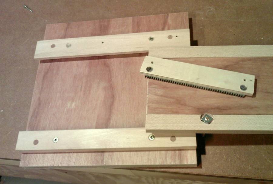
The runners and rails were made from beech, 10 x 22 x 300 and 16 x 30 x 300 mm respectively.
The runners are glued into rabbets in the sled, the rabbets are dimensioned so that the sled is clear of the base plate and rails.
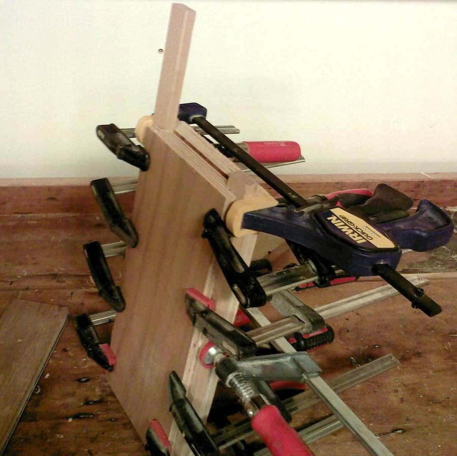
 Having made sure the outside of the runners were dead parallel (and yes,
I did need to adjust this with a hand plane), the sled was used as
spacer while fitting the rails to the base plate. Rather than gluing the
rails to the base plate I secured their position by drilling in a couple
of 6 mm dowels in each (just as easy and allows for dismantling if
needed).
Having made sure the outside of the runners were dead parallel (and yes,
I did need to adjust this with a hand plane), the sled was used as
spacer while fitting the rails to the base plate. Rather than gluing the
rails to the base plate I secured their position by drilling in a couple
of 6 mm dowels in each (just as easy and allows for dismantling if
needed).
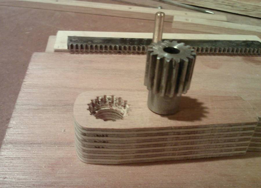 I prepared the pinion gear and rack, handle, scale, stops
etc. I happened to have a brazing rod that fit exactly in the hole of the
pinion gear (6 mm), so this was threaded and cut to length to serve as the
axle.
I prepared the pinion gear and rack, handle, scale, stops
etc. I happened to have a brazing rod that fit exactly in the hole of the
pinion gear (6 mm), so this was threaded and cut to length to serve as the
axle.
The pinion (16 mm, a common standard in this part of the world) has an outer diameter of about 17.5 mm and a smooth neck of 13 mm. It's held in the handle by pressing / hammering it into holes drilled at 16 and 13 mm respectively (the bigger hole drilled first and 6-7 mm deep).
 The rack is also standard, and the piece I had was about
140 mm long. Even though I only needed 60 mm of it, I used it as it was
and drilled and threaded a hole in each end for a 5 mm machine screw.
The rack was then screwed to a piece of ply of appropriate thickness to
keep it clear of the sled (in my case 6 mm).
The rack is also standard, and the piece I had was about
140 mm long. Even though I only needed 60 mm of it, I used it as it was
and drilled and threaded a hole in each end for a 5 mm machine screw.
The rack was then screwed to a piece of ply of appropriate thickness to
keep it clear of the sled (in my case 6 mm).
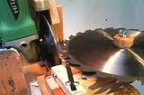
The scale is a compass rose (found on the net) glued to a piece of ply, and cut to size on the band saw using my circle cutting jig.
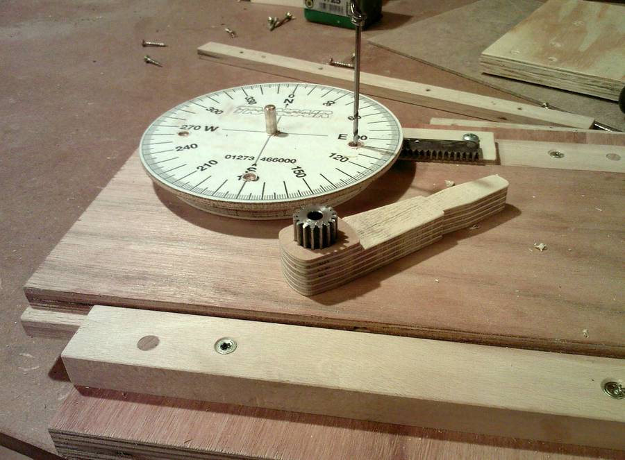 Next was to determine the position of the axle for the pinion. I
chose to place this as far from the edge of the sled as was allowed by the
overhang of the rack, and far enough from the end of the sled for the
scale wheel not to extend past it. Once the position was determined,
a 6 mm hole was drilled from the top and countersunk from the bottom
with a 20 mm Forstner bit.
Next was to determine the position of the axle for the pinion. I
chose to place this as far from the edge of the sled as was allowed by the
overhang of the rack, and far enough from the end of the sled for the
scale wheel not to extend past it. Once the position was determined,
a 6 mm hole was drilled from the top and countersunk from the bottom
with a 20 mm Forstner bit.
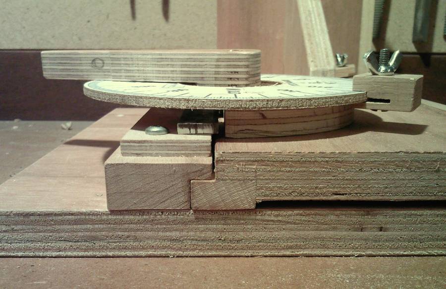
The rack needs to be mounted so there is absolutely no play between it and the pinion. Play will result in inaccurate cuts. I did this by pressing the rack hard against the wheel with this aligned with the screws (one end at a time of course), and to allow for adjustment, the “holding plate” is fixed to the rail with round headed screws.
This done, the spacer between the sled and the scale can be cut and fixed in place. Also the middle of the scale is cut away to make room for the handle and visibility of the rack and pinion during operation.
To ensure the correct position and ease of assembly, I cut a shallow
rabbet in the upright as a seat for the sled, and drilled in a couple
of dowels to receive the screws holding the fence (this as the fence
will be replaced frequently).
Last was to make the stops, then give the thing a try. The stops are blocks of oak, 12 x 22 x 32 mm with a slot cut to fit the thickness and curvature of the scale, and slid to about 5 mm from the end of the block.
I figured that the max travel I would need was about 50- 60 mm and fitted the runners accordingly.
I’d figured out that with the 16 mm pinion gear, a 10 mm travel of the sled should correspond to a turn of 72 deg and thus one deg corresponds to a travel of about 0.14 mm. Tests confirmed this to be near enough and that the kerf of the saw blade I used, corresponded to a turn of 22 deg
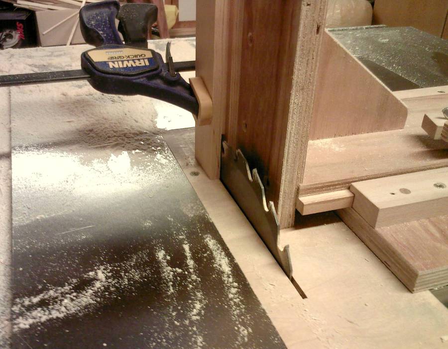 This done, it was time to make some test cuts, and it worked out as well
as I’d hoped. I first cut the mortise and then the tenon, using only
the scale for the setting. They fit well enough, but were a bit
loose, adjusting one stop by one deg cured that.
This done, it was time to make some test cuts, and it worked out as well
as I’d hoped. I first cut the mortise and then the tenon, using only
the scale for the setting. They fit well enough, but were a bit
loose, adjusting one stop by one deg cured that.
I’ve since used the jig a few times and am pleased with it.
See also:
 Jens Larsen's dust extractor Thien-baffle modifications
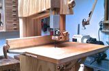
 Quick-set tenon jig
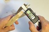 Accuracy of mortise and tenon joints
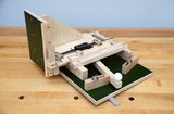 Harlan Opie's Quick-set tenon jig
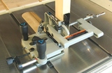 Delta tenon jig review