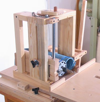
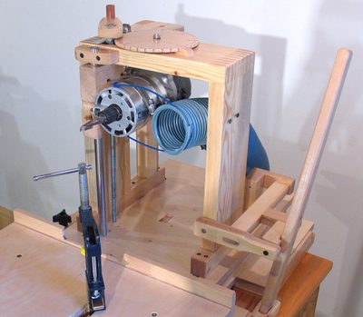
 The router is mounted inside a sort of inverted 'U' bracket. The bracket is
box joined at the top corners and double tenon joined into the pieces that mount
it against the piece of plywood.
The router is mounted inside a sort of inverted 'U' bracket. The bracket is
box joined at the top corners and double tenon joined into the pieces that mount
it against the piece of plywood.
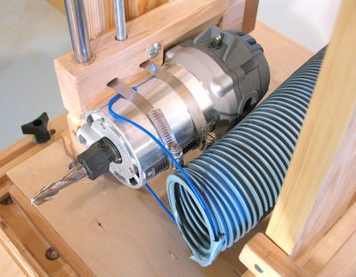 For the router mount, I cut a cove in a piece of maple to match the
curvature of the router's 3.5" sleeve. I used
this method to cut the cove.
For the router mount, I cut a cove in a piece of maple to match the
curvature of the router's 3.5" sleeve. I used
this method to cut the cove.
I then just attached the router to the mount with a pair of hose clamps. I originally had some ideas for a more robust bracket to hold the router, but decided to try just clamping it on with hose clamps first, and was pretty happy with how those worked out.
The precise position is provided by the shape cut into the block, and the hose
clamps are just to press it against the block, so their stiffness is not an issue.
Really, it would work almost as well if I held the router in place with tight
enough bungee cords.
The router is mounted inside a sort of inverted 'U' bracket. The bracket is
box joined at the top corners and double tenon joined into the pieces that mount
it against the piece of plywood.
I'm sometimes asked what router I used. I used the store-brand "Mastercfart" router from a Canadian hardware store, called "Canadian tire". It only cost $125 + tax.
Most fixed-based routers will have a 3.5" (89 mm) diameter body suitable for this application. However, fixed based routers are hard to find outside of Canada and USA. More about this at the end of this article
If you live outside of North America, this style of router is harder to find,
you may have to order it online. Don't order it from the US or Canada, because
we use 110 volts for our electrical system here.
 The router slides up and down along a 5/8" polished stainless steel shaft.
The router mount slides up and down along this shaft with two bronze bushings,
one pressed into a hole in the mounting block from the top, the other from below.
The router slides up and down along a 5/8" polished stainless steel shaft.
The router mount slides up and down along this shaft with two bronze bushings,
one pressed into a hole in the mounting block from the top, the other from below.
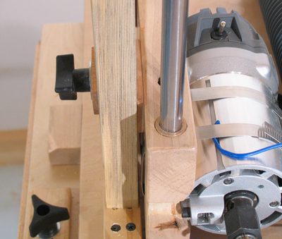
The router's vertical position can also be locked by tightening the knob in the left of this photo. This presses the router mounting bracket against the frame, locking it in place and stiffening the whole assembly.
The vertical shaft is nearest the front, so that it's nearest to the router bit.
The location of the router bit is what really matters, so it made sense to
put the guides as close as possible to that.
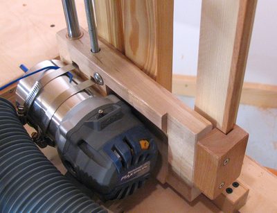 But the single shaft doesn't secure the assembly against rotating about its shaft.
So to keep the router pointing straight and forward, there is another guide rail
in the back, with a block that fits around it.
But the single shaft doesn't secure the assembly against rotating about its shaft.
So to keep the router pointing straight and forward, there is another guide rail
in the back, with a block that fits around it.
The guide shaft, bushings, and another guide parallel but offset from the shaft is the same approach that I had used on my quick set tenon jig
If this machine were made all out of metal in a machine shop, a logical thing
would have been to have a second guide shaft just like the one in the front.
But aside from not having a second polished shaft handy, it would also
have been impossible to make it this apparatus precise enough that it would
slide freely, especially in the face of humidity changes.
 The router is moved up and down by turning a 3/8" threaded rod with a crank.
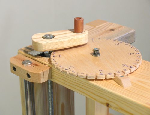
I found that due to vibration, the crank would slowly drift downward on its own, especially if I didn't tighten the vertical router position knob. So I added a "detent" mechanism that gives the crank six clicks per turn. It's just a spring loaded piece of metal that pushes against a nut on the shaft.
For many types of joints, I need to move the router up and down by a set number of turns for each joint. I found that I'm not that good at keeping track of how many turns I have put on the crank. So I added a "counter wheel" to count the number of turns. This wheel is advanced by a pin in the bottom of the crank, and is advanced by one notch for each turn, not unlike how a Geneva drive mechanism works. The difference is that the position of the intermittently turning wheel is not locked in between advances, whereas on a Geneva drive it is. So if the wheel is turned by half a notch when the pin is not engaged, it will jam on the next turn. To make this less likely, I made sure it turns with a fair bit of friction. There is a spring between the mounting screw and the wheel to press it down.
The advantage of the counter wheel not locking is that I can change where "zero" is,
so that's one less position I have to remember.
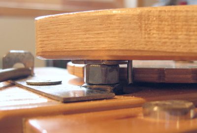 This view, looking under the crank, shows more detail. The nut in the middle of the photo
is a space between the crank, and the ball bearing further down. You can see the
pin to the right of the nut, which is the part that slides into one of the
notches and advances the wheel by one notch.
To the left, you can see the piece of metal that is pressing against a larger nut by
a spring. The hexagon shape of the nut makes for six "clicks" for each turn of the crank.
This view, looking under the crank, shows more detail. The nut in the middle of the photo
is a space between the crank, and the ball bearing further down. You can see the
pin to the right of the nut, which is the part that slides into one of the
notches and advances the wheel by one notch.
To the left, you can see the piece of metal that is pressing against a larger nut by
a spring. The hexagon shape of the nut makes for six "clicks" for each turn of the crank.
This feature is also important for cutting multiple slots side by side. These need
to be spaced within a few thousandth's of an inch of each other. Because the router
moves 1 1/16'th of an inch for each turn (1.58 mm), stopping the crank just 15 degrees
off from where it was last time would be a .0025" error in vertical position, which
would make the machine noticeably less consistent.
 I designed the jig to have a very large range of vertical travel. The router
can be moved up and down by about 22 cm (nearly 9"). This is overkill, but I figured
it might be handy if I want to make a very long series of slots across the side
of a wide board, such as if I wanted to make some super strong T-joints by making
16 mortises side by side.
I designed the jig to have a very large range of vertical travel. The router
can be moved up and down by about 22 cm (nearly 9"). This is overkill, but I figured
it might be handy if I want to make a very long series of slots across the side
of a wide board, such as if I wanted to make some super strong T-joints by making
16 mortises side by side.
This feature could also come in handy if I jigged something large up on the table.
But if I was building it again, I'd probably make it have just 15 cm of vertical travel, which would still be lots. Not that the large vertical travel is a problem, just that having less would make the machine a little more compact.