 Eventually, I tried some keyboard drawer slides. These, it turned out, had much more
rigidity to them and were closer to what I needed. But they still needed modifications.
Eventually, I tried some keyboard drawer slides. These, it turned out, had much more
rigidity to them and were closer to what I needed. But they still needed modifications.
 My original idea for sliders for the slot mortising machine was to use some
full extension drawer slides. I figured on recombining two pairs of slides, using
the inside ball races for one direction, and the outside races for the other, and using
the balls from both slides in both for extra rigidity.
My original idea for sliders for the slot mortising machine was to use some
full extension drawer slides. I figured on recombining two pairs of slides, using
the inside ball races for one direction, and the outside races for the other, and using
the balls from both slides in both for extra rigidity.
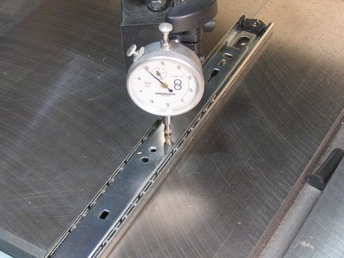
I used a dial indicator to measure how much give the slides would have under various pressures and motion, and found that at least the outside part of the slide had too much give for my application. That, and the middle track of the slide was too hard to mount, and too flexible.
So I put aside the idea of using drawer slides. But then I came across some keyboard drawer slides, which which turned out to be a much closer to what I needed.
Eventually, I tried some keyboard drawer slides. These, it turned out, had much more
rigidity to them and were closer to what I needed. But they still needed modifications.
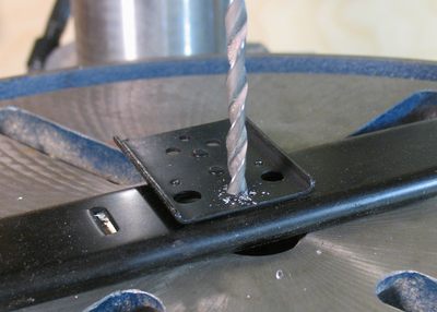
Both halves of the slides had protruding mounting brackets and tabs. The mounting brackets (for the stationary part) were spot-welded on. By drilling out most of the welds, the bracket could be broken off without deforming the slide itself.
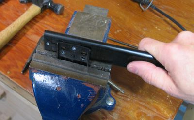 I broke what was left of the welds after drilling by clamping the bracket in
a vise and twisting the rail back and forth until it popped apart.
I broke what was left of the welds after drilling by clamping the bracket in
a vise and twisting the rail back and forth until it popped apart.
There were also some tabs sticking out of the other part of the rail. I ground these off with a cut off disk on a Dremel tool.
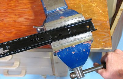 Next I tightened up the rails a little bit by squeezing them in a vise. This operation is
a little tricky. It's a matter of giving the rail enough of a squeeze to deform just slightly.
I did this by squeezing the rail in the vise, then releasing it, and
sliding it so that the balls were in the part that I had squeezed to check the tightness.
The metal deforms elastically a fair bit before before it actually bends, so it's not possible
to check for tightness while actually squeezing the rail.
I ended up squeezing, then releasing and sliding back and forth to check fit, then squeezing
again, slightly harder, testing again, and so forth, until I got the desired fit. I had to do this
for each vise-width along the rail.
Next I tightened up the rails a little bit by squeezing them in a vise. This operation is
a little tricky. It's a matter of giving the rail enough of a squeeze to deform just slightly.
I did this by squeezing the rail in the vise, then releasing it, and
sliding it so that the balls were in the part that I had squeezed to check the tightness.
The metal deforms elastically a fair bit before before it actually bends, so it's not possible
to check for tightness while actually squeezing the rail.
I ended up squeezing, then releasing and sliding back and forth to check fit, then squeezing
again, slightly harder, testing again, and so forth, until I got the desired fit. I had to do this
for each vise-width along the rail.
 There is, of course, risk of over-bending the rail in this procedure. But if you build
such a machine, you will have to buy at least one extra set of slides
just to get more ball bearings and bearing guides to double up on the number of ball bearings.
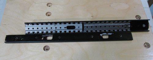
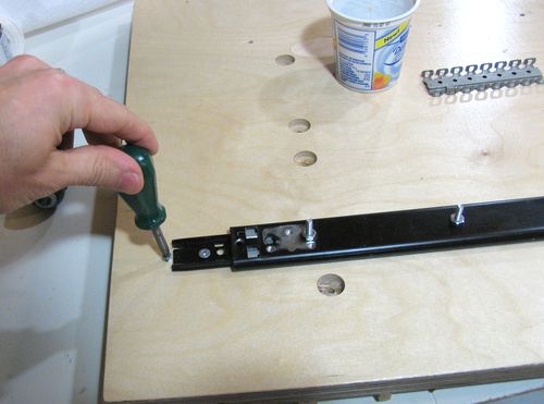
The picture at left shows a rail with two ball bearing guides in it. With both in, I can still
get 15 cm of motion end to end, which is sufficient for my mortising machine.
There is, of course, risk of over-bending the rail in this procedure. But if you build
such a machine, you will have to buy at least one extra set of slides
just to get more ball bearings and bearing guides to double up on the number of ball bearings.
The picture at left shows a rail with two ball bearing guides in it. With both in, I can still
get 15 cm of motion end to end, which is sufficient for my mortising machine.
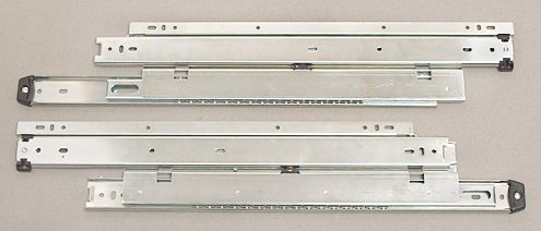 Another type of slide that would work quite well for this is tiered full extension slides.
If I had thought of this type of slide ahead of time, I would probably have used these instead.
The advantage of these is that once the welds are drilled out, you are left with two
usable slides out of each slide. They tend to be a bit longer though, so it won't be possible to
shield them from dust as well as the shorter slides. But longer is better.
If you do use this type of slide, you may still want to buy a second pair, though,
just to get more balls and ball cages to double up the number of balls in the tracks.
Slides like this aren't available at the home depot, but Lee Valley Tools has them.
Another type of slide that would work quite well for this is tiered full extension slides.
If I had thought of this type of slide ahead of time, I would probably have used these instead.
The advantage of these is that once the welds are drilled out, you are left with two
usable slides out of each slide. They tend to be a bit longer though, so it won't be possible to
shield them from dust as well as the shorter slides. But longer is better.
If you do use this type of slide, you may still want to buy a second pair, though,
just to get more balls and ball cages to double up the number of balls in the tracks.
Slides like this aren't available at the home depot, but Lee Valley Tools has them.
I have since created a more detailed article and video on modifying drawer slides for this purpose.
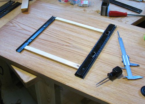 The ball tracks need to be exactly parallel for the machine to move freely.
As spacers, I used two pieces of wood of exactly the same length.
The spacers were cut from one piece which I cut to length first, and then rip cut along
its length to make sure I had two pieces of exactly the same length.
The ball tracks need to be exactly parallel for the machine to move freely.
As spacers, I used two pieces of wood of exactly the same length.
The spacers were cut from one piece which I cut to length first, and then rip cut along
its length to make sure I had two pieces of exactly the same length.
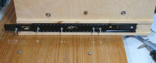
I ended up drilling several mounting holes into the rails along their length, seeing that I had cut and ground off the original mounting points. The pieces are mounted with #8-32 countersink head machine screws through the plywood, with a nut on the other side of the plywood.
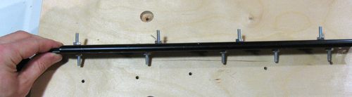 This photo shows one of the prepared tracks, ready for mounting. I had to insert the
mounting screws into the halves of the track before reassembling the track with its ball guides.
This photo shows one of the prepared tracks, ready for mounting. I had to insert the
mounting screws into the halves of the track before reassembling the track with its ball guides.
This is a very fiddly sort of task, and the loose counter sink screws kept jamming against the ball guides. So I temporarily held the countersink screws in place with some nuts. I removed these nuts again when I mounted it against the plywood.
Once mounted, the machine screws are held in place by nuts in 3/4" counter bored holes from the other side. You can see some of these holes in the next photo.
 Part of my preparation of the ball tracks involved removing most of the stops from the tracks, so
that I could disassemble it all. As such, there is nothing that prevents the ball tracks
from eventually working their way out of the machine over time. So I put a small wood
screw at the end of the tracks to act as a stop for the ball guides.
Part of my preparation of the ball tracks involved removing most of the stops from the tracks, so
that I could disassemble it all. As such, there is nothing that prevents the ball tracks
from eventually working their way out of the machine over time. So I put a small wood
screw at the end of the tracks to act as a stop for the ball guides.
 Assembling the slides and plywood layers was tricky. I had to do it in just the right order.
If I had just assembled the middle layer with its slider to
the base, I would no longer have had access to the bottom of the middle layer, and would not
have been able to mount the tracks onto the layer above. So I had to mount both sets of
tracks to the middle layer, and only then mount the middle layer onto the base.
Assembling the slides and plywood layers was tricky. I had to do it in just the right order.
If I had just assembled the middle layer with its slider to
the base, I would no longer have had access to the bottom of the middle layer, and would not
have been able to mount the tracks onto the layer above. So I had to mount both sets of
tracks to the middle layer, and only then mount the middle layer onto the base.
The above shot shows one of the rails for side to side motion ready to mount onto the base piece of plywood. You can see holes for where the screws stick out. You can also see two screws in the base nearer to the camera. Another screw in the plywood above bumps against these screws, to limit the side to side range of motion.
Before putting this together, I still had to remove the nuts that I temporarily put on the mounting screws. With the nuts removed, the mounting screws just flop around loosely inside their countersink holes.
 Getting all the screws go into their holes all at once was tricky. Especially because
I drilled the holes to be just big enough for the screws, so that things would stay
aligned precisely.
Getting all the screws go into their holes all at once was tricky. Especially because
I drilled the holes to be just big enough for the screws, so that things would stay
aligned precisely.
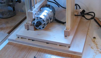 This photo shows the layers assembled, with the router mounting bracket on it already.
I had not yet put a lot of trim around the sliders yet.
This photo shows the layers assembled, with the router mounting bracket on it already.
I had not yet put a lot of trim around the sliders yet.
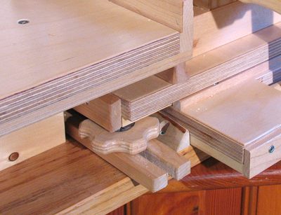
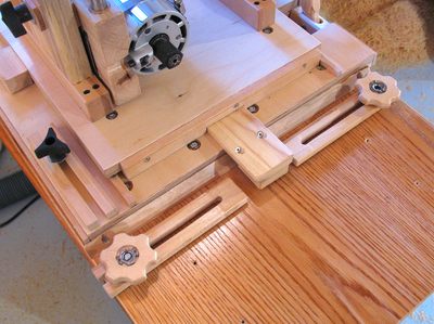 In this photo, the trim to protect the sliders from sawdust is installed.
I also installed the side to side stops. The wooden knobs on either side are to hold down the stops (the parts with a slot in them). These limit how far the piece of wood between them can move. This piece in the middle in turn is attached to the middle plywood layer, so that it moves side to side with the whole carriage.
I have to admit that I hadn't really thought about where to put the side to side stops until I actually built them. And it turned out, the only logical place to put them was in front of the slider, which ends up being under the table.
 Space is a little tight around the stops. With the router carriage slid all the way
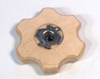 forward and to one side, it ends up overhanging the knobs. For this reason, I was unable
to use off the shelf plastic knobs. Instead, I made some very low profile knobs cut
out of 3/8" birch plywood. For the thread in the knob, I just installed a T-nut.
The T-nut is recessed in the knob a little bit, so that it doesn't add thickness.
I also pre-drilled holes for the T-nut's prongs. I don't think T-nuts are normally
meant to be hammered into birch plywood, but this way, they installed without a
great amount of force.
forward and to one side, it ends up overhanging the knobs. For this reason, I was unable
to use off the shelf plastic knobs. Instead, I made some very low profile knobs cut
out of 3/8" birch plywood. For the thread in the knob, I just installed a T-nut.
The T-nut is recessed in the knob a little bit, so that it doesn't add thickness.
I also pre-drilled holes for the T-nut's prongs. I don't think T-nuts are normally
meant to be hammered into birch plywood, but this way, they installed without a
great amount of force.
I may make knobs like that in the future - the plastic knobs are not particularly cheap, and these wooden knobs are actually kind of nice to use.