 Having modified the belt tension and tracking mechanism,
I was finally ready to build a base and table allowing this sander to be used
as an edge belt sander.
Having modified the belt tension and tracking mechanism,
I was finally ready to build a base and table allowing this sander to be used
as an edge belt sander.
Having modified the belt tension and tracking mechanism,
I was finally ready to build a base and table allowing this sander to be used
as an edge belt sander.
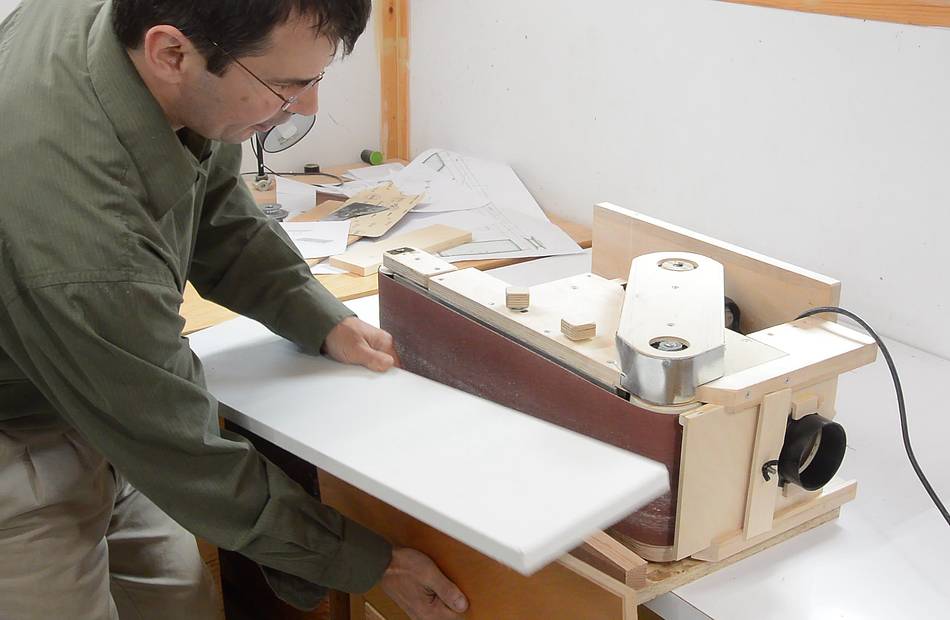
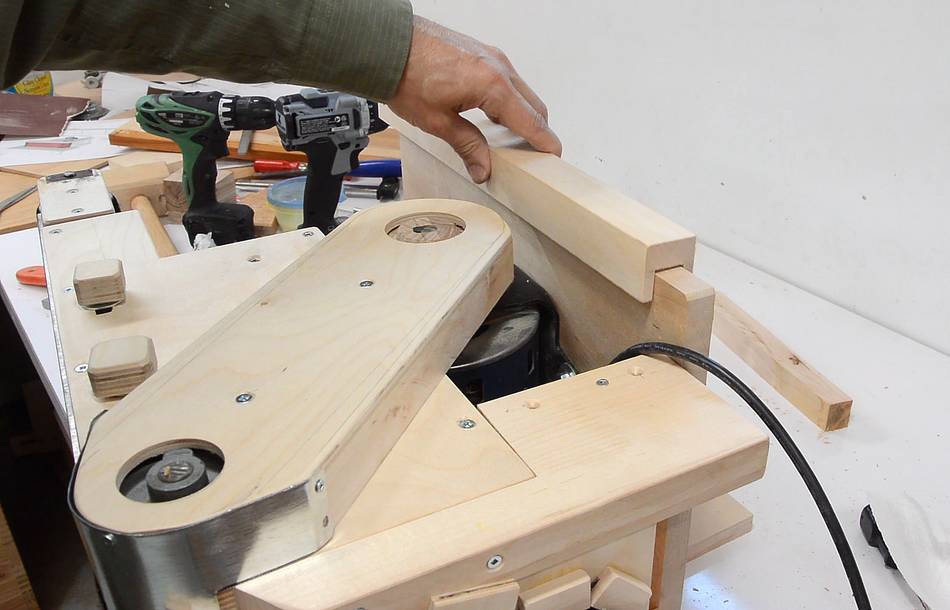
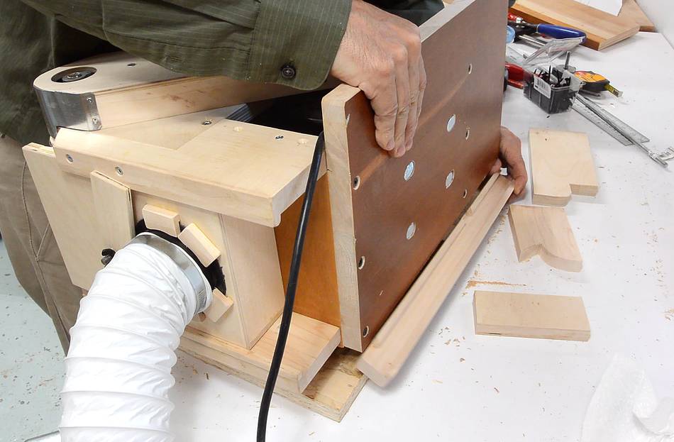
The idea was to lie the sander on its side and have a height adjustable table in front of it. Here showing how the pieces will go together.
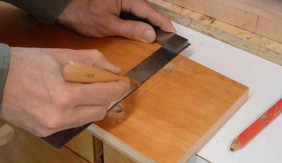 Height can be adjusted by having the table support clamp to the base at
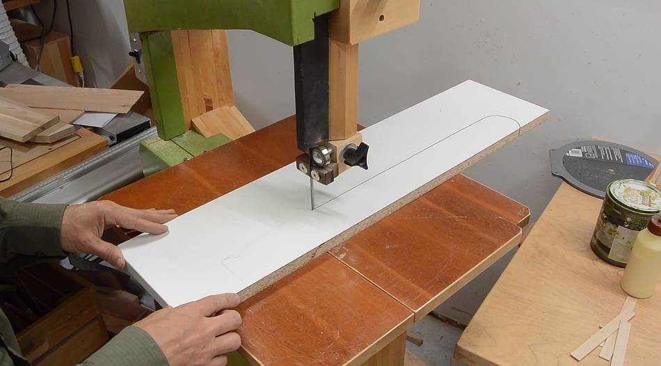
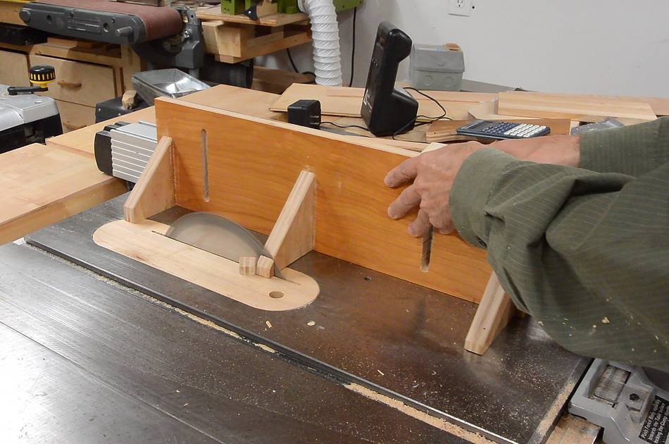
different heights, using slots in that part. Here I'm scoring where I
need to cut to avoid tearout with the jigsaw.
Height can be adjusted by having the table support clamp to the base at
different heights, using slots in that part. Here I'm scoring where I
need to cut to avoid tearout with the jigsaw.
 Then cutting the slot with a jigsaw.
I drilled a 3/8" hole on either end of the slot, but drilled two overlapping holes where the cut starts so I can start the jigsaw blade right on the edge of the slot.
 I needed two threaded knobs, like this one borrowed from my
tilting router lift
I needed two threaded knobs, like this one borrowed from my
tilting router lift
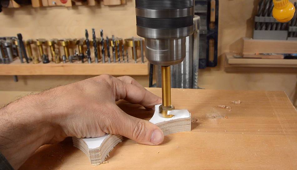
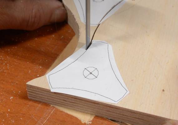 I printed out 1:1 templates for the knobs from my CAD model, then cut them
out on the bandsaw. I drilled a shallow hole on one side of the knob
to recess a carriage bolt head, then drilled a hole for the bolt to pass
through.
I printed out 1:1 templates for the knobs from my CAD model, then cut them
out on the bandsaw. I drilled a shallow hole on one side of the knob
to recess a carriage bolt head, then drilled a hole for the bolt to pass
through.
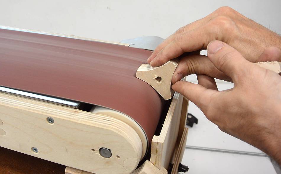 Then smoothing the sides and edges on the belt sander.
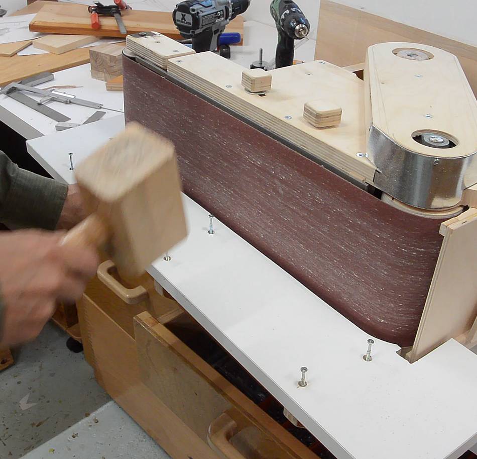
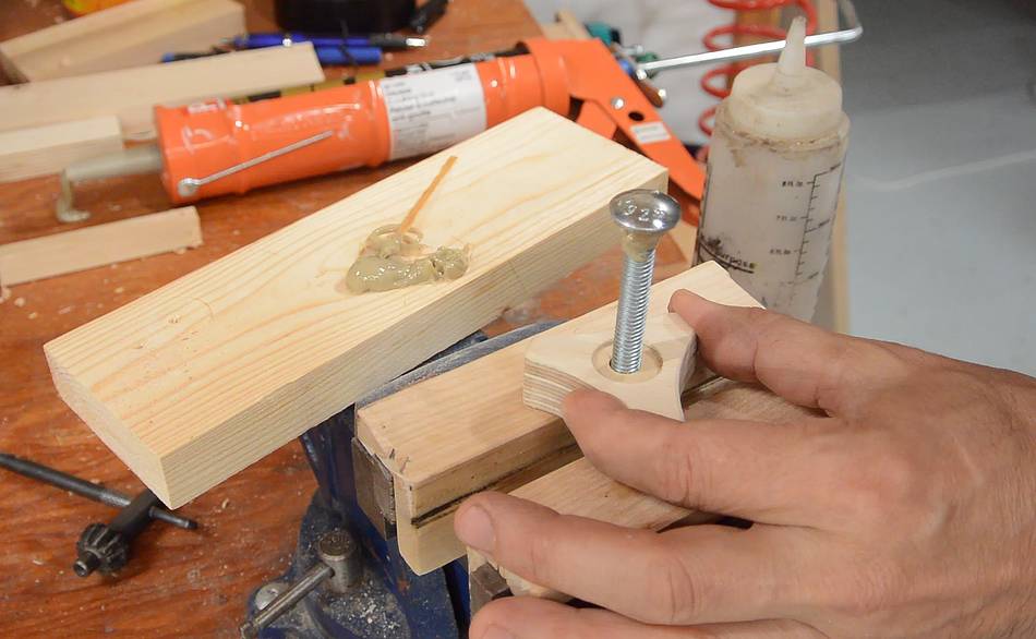 After that, I put some construction adhesive below the carriage
bolt head and hammered it into the knob. The adhesive isn't really
necessary, just that I had an open tube of it already, so might as
well use it before it goes bad.
After that, I put some construction adhesive below the carriage
bolt head and hammered it into the knob. The adhesive isn't really
necessary, just that I had an open tube of it already, so might as
well use it before it goes bad.
 I decided to add some gussets to the table support to help hold the table.
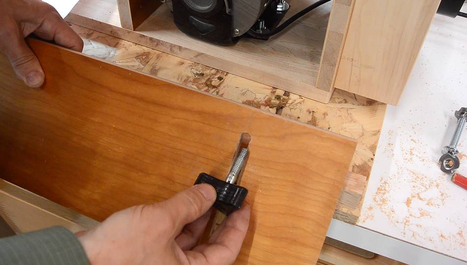
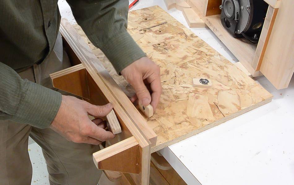
Because I'm using recycled plywood, I have to scrape the old varnish off where the gussets glue on.
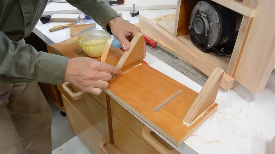 Then gluing on the gussets. I didn't have a good way to clamp these, so I just
put it aside without clamping while the glue dried.
Then gluing on the gussets. I didn't have a good way to clamp these, so I just
put it aside without clamping while the glue dried.
 The front of the base needs a ledge that the support bolts on to.
I used a piece of hardwood, and drilled two overlapping 3/8" holes to form a short slot. The hole is elongated to leave a bit of room for tilting the table sideways.
 Then screwing this ledge to the base. The ledge actually goes on top,
but I flipped
it upside-down here to make it easier to screw it on.
Then screwing this ledge to the base. The ledge actually goes on top,
but I flipped
it upside-down here to make it easier to screw it on.
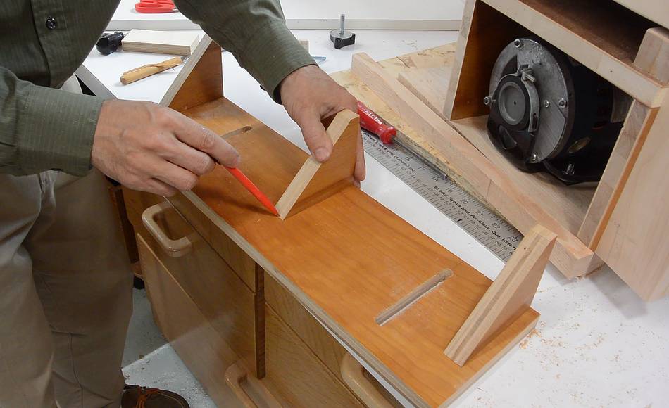
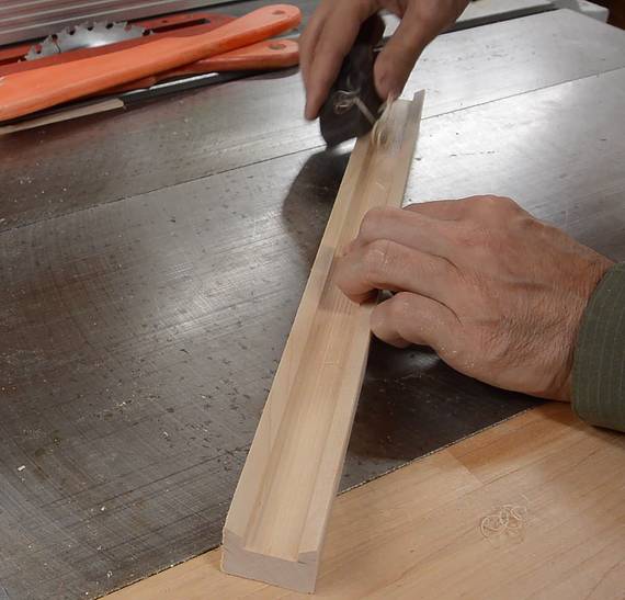
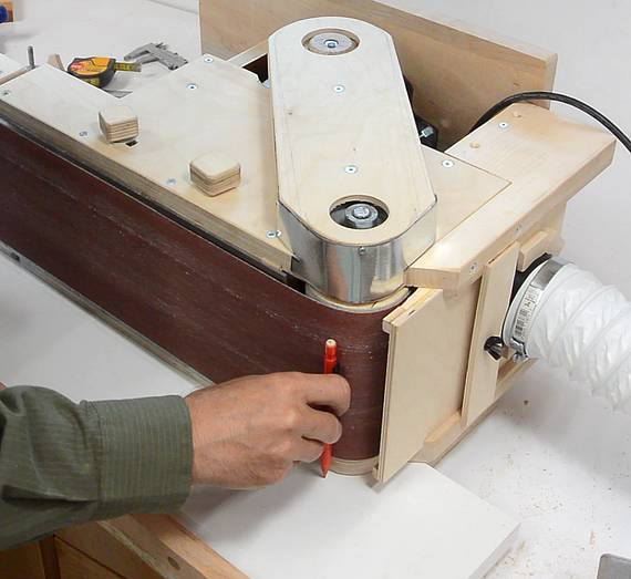 Lining up what will become the table with the sander on top,
then tracing around the belt with a pencil.
Lining up what will become the table with the sander on top,
then tracing around the belt with a pencil.
 I cut that out on the bandsaw. You can see how the end of the
table has a hook on it to curve around the idler roller of the
sander, but this made it too awkward to get the table on and
off, so I cut the hook straight.
I cut that out on the bandsaw. You can see how the end of the
table has a hook on it to curve around the idler roller of the
sander, but this made it too awkward to get the table on and
off, so I cut the hook straight.
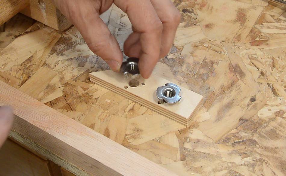
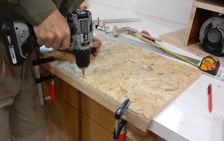
 The knobs to hold the table need to screw into something. I'm using
some T-nuts in a small piece of plywood (with holes for the prongs
pre-drilled). Because the threaded knobs I made were barely long enough,
I needed the T-nuts to go all the way through the plywood so the knob
would still reach them.
The knobs to hold the table need to screw into something. I'm using
some T-nuts in a small piece of plywood (with holes for the prongs
pre-drilled). Because the threaded knobs I made were barely long enough,
I needed the T-nuts to go all the way through the plywood so the knob
would still reach them.
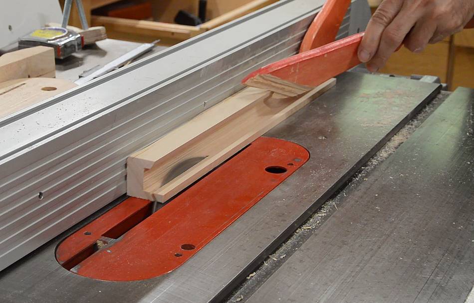
I cut the plywood to the right thickness on the table saw before adding the
T-nuts.
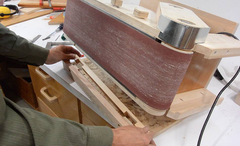
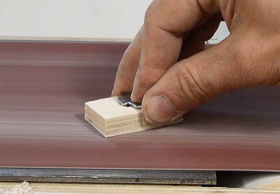 But it was still a bit too thick, so, with the T-nut already pressed in,
I sanded it down some more on the belt sander.
But it was still a bit too thick, so, with the T-nut already pressed in,
I sanded it down some more on the belt sander.
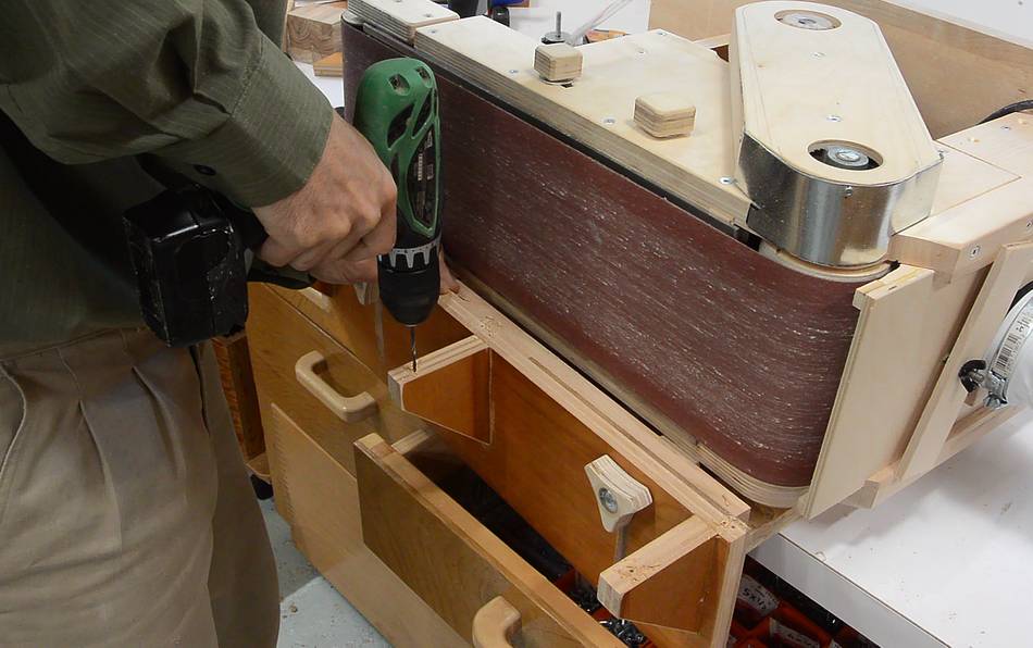
 By now, the glue holding the gussets onto the table was sufficiently dry,
so I drilled some holes from the back and screwed it on.
By now, the glue holding the gussets onto the table was sufficiently dry,
so I drilled some holes from the back and screwed it on.
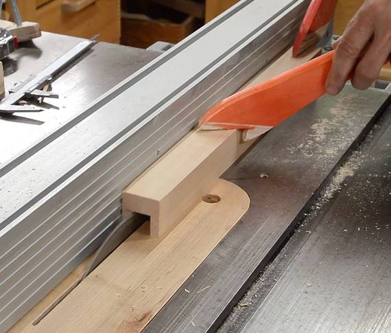
 Once I checked how things fit together, I realized the gussets were a
bit too deep, so I shortened them on the table saw (I hadn't added
the gussets in the CAD model, so I just made them "big enough").
Once I checked how things fit together, I realized the gussets were a
bit too deep, so I shortened them on the table saw (I hadn't added
the gussets in the CAD model, so I just made them "big enough").
 Finally attaching the table support to the base.
 Checking how the table fits on.
 After marking where the holes on the table need to go, I drilled them on
the drill press, then put the table back on the supports and, with screws
in the holes, tapped them to mark where the pilot holes need to go.
After marking where the holes on the table need to go, I drilled them on
the drill press, then put the table back on the supports and, with screws
in the holes, tapped them to mark where the pilot holes need to go.
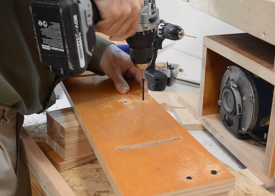
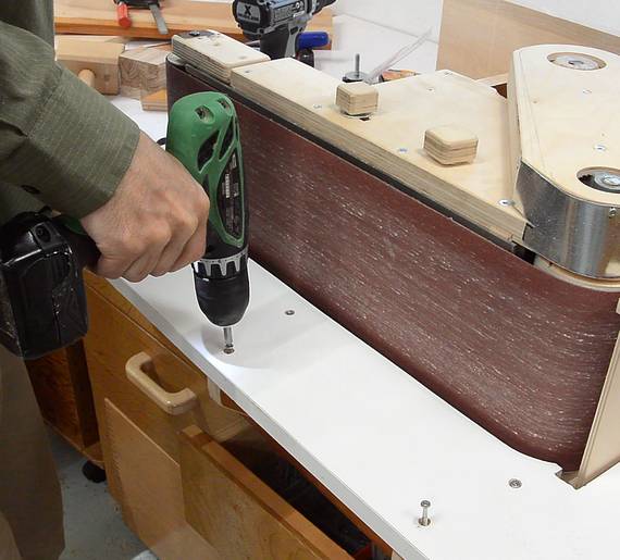 Then drilling the pilot holes and screwing on the table.
 The table can be tilted side to side by a small amount.
This can be useful to wear the belt more evenly,
or if I want to use the roller at the end like a spindle sander,
with a bit of tilt.
The table can be tilted side to side by a small amount.
This can be useful to wear the belt more evenly,
or if I want to use the roller at the end like a spindle sander,
with a bit of tilt.
 I made a sort of wooden C-channel to fit around the base of the machine.
 I then realized getting the base of the sander in and out of this channel was
too tricky, so I beveled the inside edges of it on the table saw (also making
it less deep). I used a small hand
plane to cut off the sharp edges, and later also to round the inside
corners a bit more to make it easier to tilt the sander out of the slot.
I then realized getting the base of the sander in and out of this channel was
too tricky, so I beveled the inside edges of it on the table saw (also making
it less deep). I used a small hand
plane to cut off the sharp edges, and later also to round the inside
corners a bit more to make it easier to tilt the sander out of the slot.
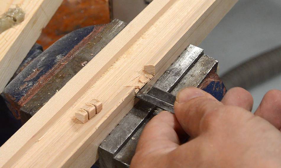 I had to chisel two notches on the side of the channel to fit around the
vertical parts of the base.
I had to chisel two notches on the side of the channel to fit around the
vertical parts of the base.
 This channel fits under the base when the sander is tipped on its side.
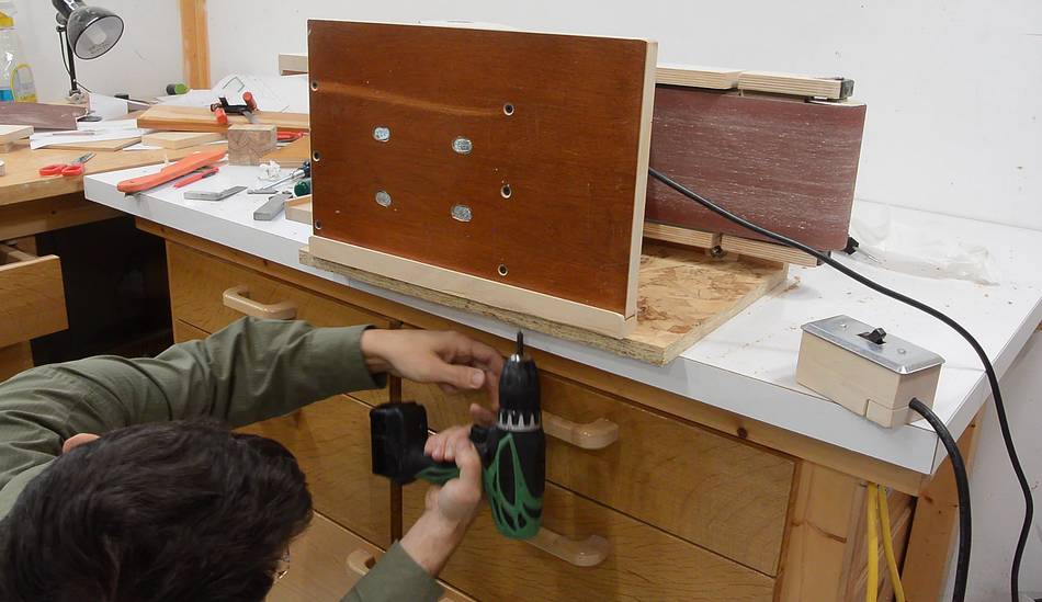 With the sander on the channel, and aligned the way I wanted it, I drilled
some pilot holes from below and screwed it on.
With the sander on the channel, and aligned the way I wanted it, I drilled
some pilot holes from below and screwed it on.
 So far, the front edge of the sander was just resting on the nut holders
that I made earlier. I made a wider rail to rest it on. This rail has
two notches cut out for the nut holders, which allows them to slide side-to-side
a little, but still keeps them in place.
So far, the front edge of the sander was just resting on the nut holders
that I made earlier. I made a wider rail to rest it on. This rail has
two notches cut out for the nut holders, which allows them to slide side-to-side
a little, but still keeps them in place.
 Finally, trying out the sander in edge belt sander mode.
 When sanding hard near the edges of the belt, the tracking drifts
to the side a little. This is probably because I made the drive roller
the crowned one. In hindsight, it would have made more sense if the
idler roller was the crowned roller. I'll change the plans
to reflect that.
When sanding hard near the edges of the belt, the tracking drifts
to the side a little. This is probably because I made the drive roller
the crowned one. In hindsight, it would have made more sense if the
idler roller was the crowned roller. I'll change the plans
to reflect that.
I originally figured I'd mostly use the idler roller for sanding curves because it has fewer obstructions around it.
But with dust collection on the drive roller side, it makes more sense to do most of the curve sanding on that side. So it would make more sense for that roller to be perfectly cylindrical.
 Other than a power switch, and paint, this sander was finally done!
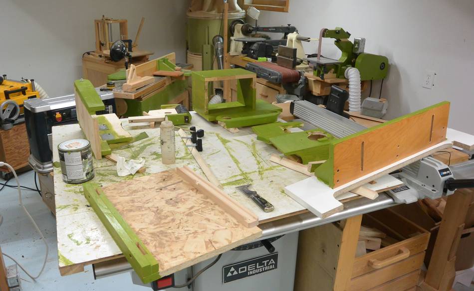
 Then it was time to take the whole thing apart and paint it.
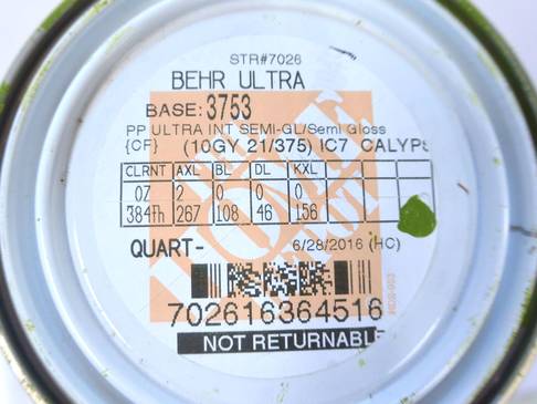
Some hate the shade of green I use, but others have asked for the code for that colour. At right, the code on the can from The Home Depot, if you want them to mix the exact same colour for you.
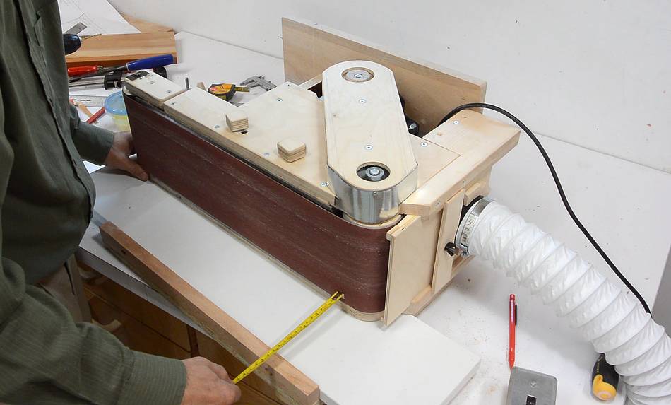
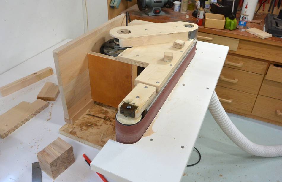
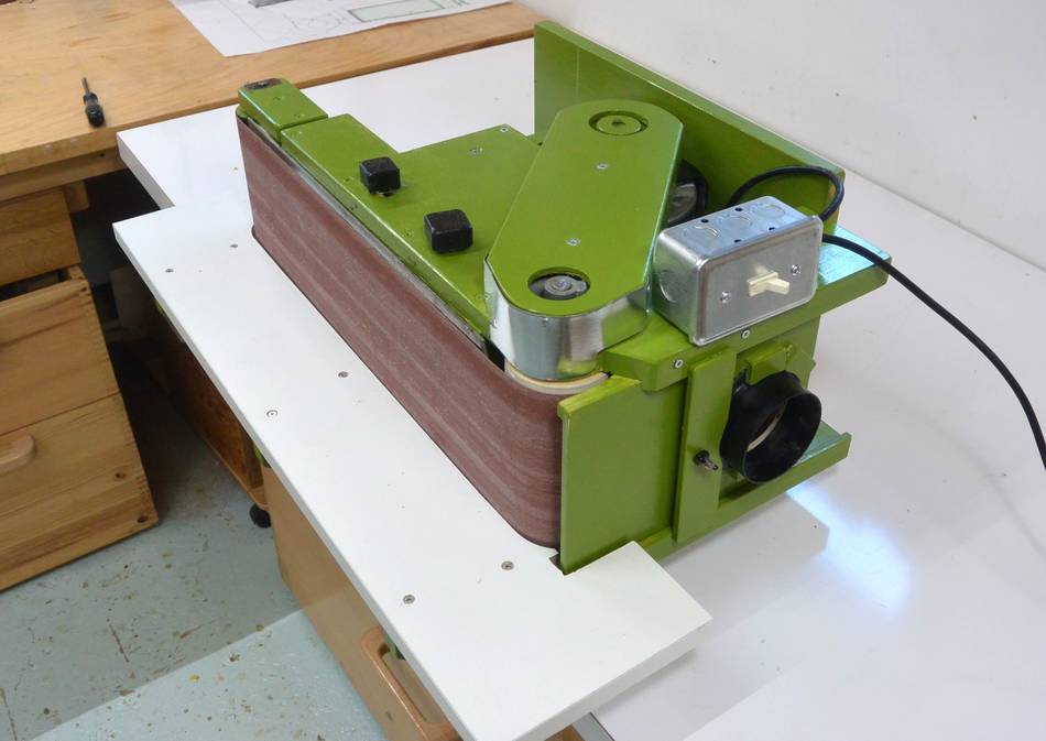 And here it is, reassembled, in edge belt sander mode.
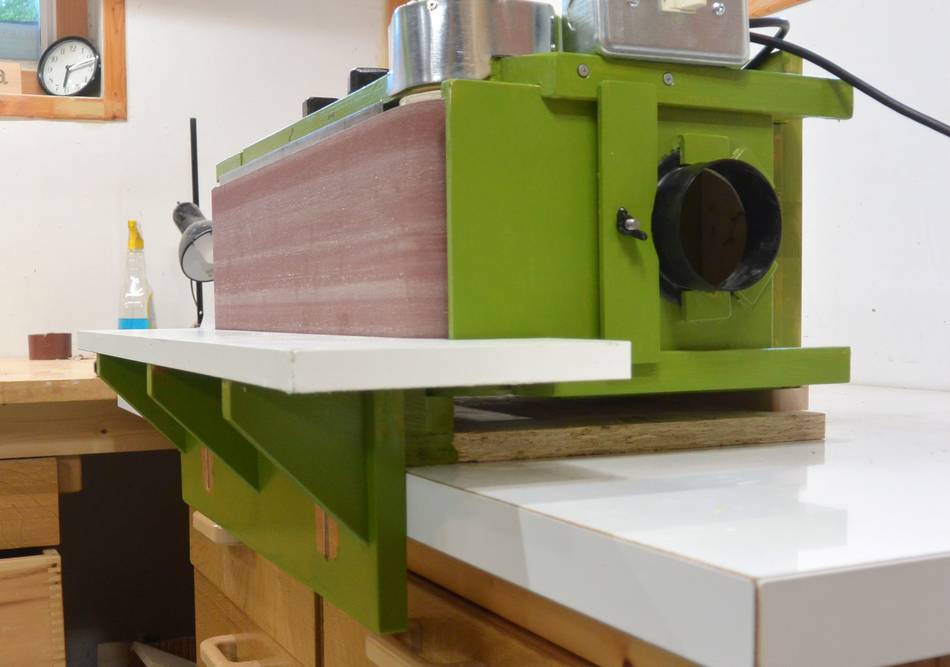 Looking along the end of the sander. Note how the sander unit
is a few centimeters above the base. This provides better air flow
for cooling the motor.
Looking along the end of the sander. Note how the sander unit
is a few centimeters above the base. This provides better air flow
for cooling the motor.
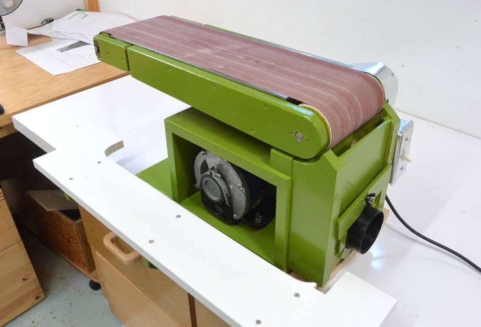 And tipped up vertically for regular sander mode. The sander neatly fits
in the middle of the base, between the supports. The table
is of course completely redundant in this mode.
And tipped up vertically for regular sander mode. The sander neatly fits
in the middle of the base, between the supports. The table
is of course completely redundant in this mode.
 Belt sander build part 1
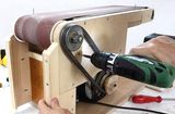 Belt sander build part 2
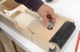 Belt sander adjustments
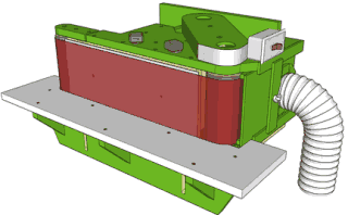 Belt sander plans
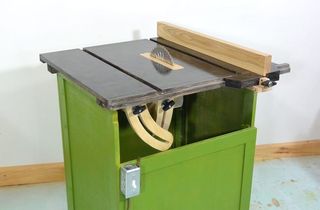 More wooden woodworking machines