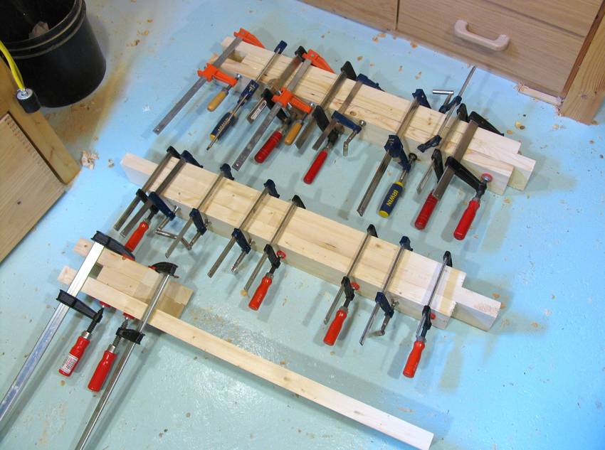
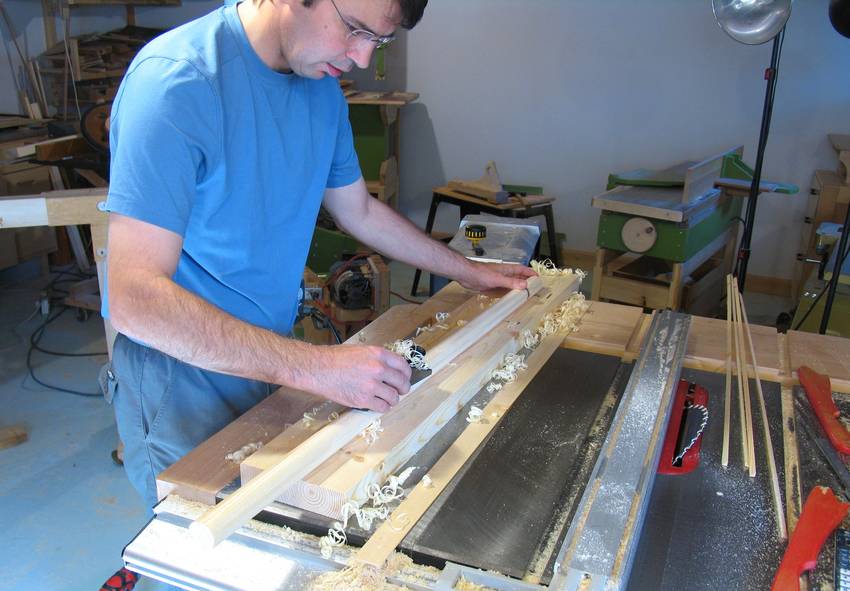
 The sawmill is made from pieces of 2x4 glued together in three layers.
I planed about a millimeter off each side of the 2x4s to get smooth
flat surfaces for better glue joints.
The sawmill is made from pieces of 2x4 glued together in three layers.
I planed about a millimeter off each side of the 2x4s to get smooth
flat surfaces for better glue joints.
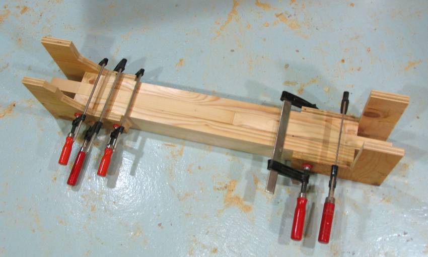 The corner joints of the frame are reinforced with pieces of plywood.
These are glued to the top horizontal, but screwed to the
other parts of the frame. This allows the frame to be taken apart
for moving or putting it away.
The corner joints of the frame are reinforced with pieces of plywood.
These are glued to the top horizontal, but screwed to the
other parts of the frame. This allows the frame to be taken apart
for moving or putting it away.
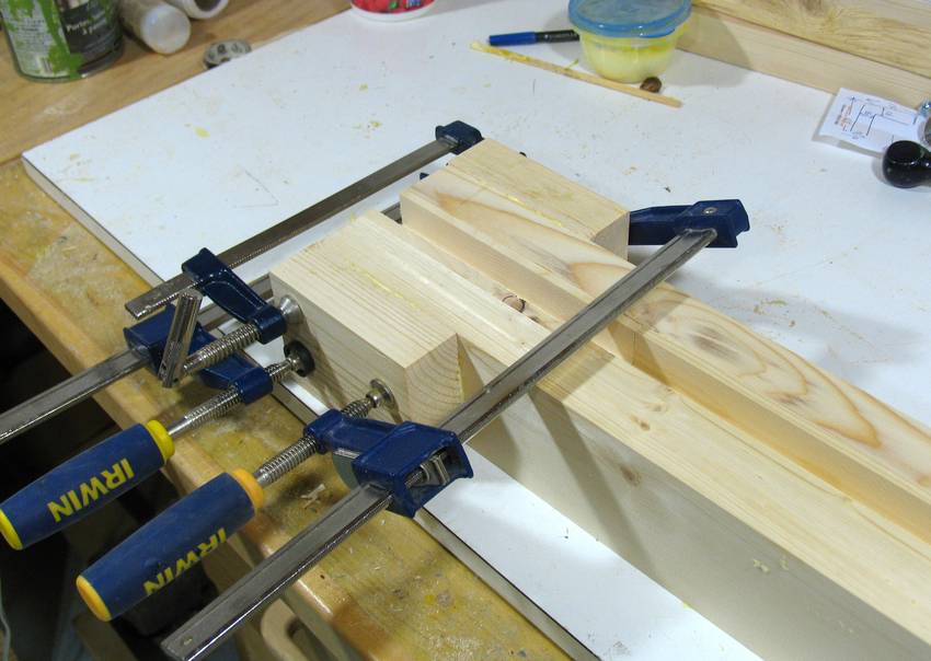
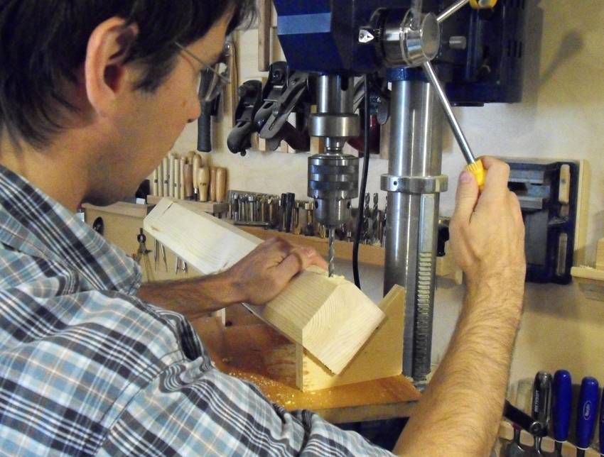
 Drilling the bolt holes in the corners. I'm using a drill guide and an extra long
drill to drill all the way through the frame. I didn't have an extra long drill
of exactly the right diameter, so after drilling the hole through, I
used a drill of the right size from either end to enlarge the holes.
Drilling the bolt holes in the corners. I'm using a drill guide and an extra long
drill to drill all the way through the frame. I didn't have an extra long drill
of exactly the right diameter, so after drilling the hole through, I
used a drill of the right size from either end to enlarge the holes.
If storage space is not an issue for you, you could improve and simplify this design by just gluing the corners together.
 The vertical member on the right side (facing the bottom side of the bandsaw)
has a groove cut into it to guide the bandsaw up and down.
The vertical member on the right side (facing the bottom side of the bandsaw)
has a groove cut into it to guide the bandsaw up and down.
Here I'm gluing some blocks of wood to the end of it to allow it to be bolted to the horizontal part that will ride on the track.
 The right side of the frame is designed to ride on a track
as shown here. The wheels are roller blade wheels, rolling on a 2x4 that
has the edges chamfered at 45-degrees.
The right side of the frame is designed to ride on a track
as shown here. The wheels are roller blade wheels, rolling on a 2x4 that
has the edges chamfered at 45-degrees.
This keeps the carriage aligned, and also allows sawdust to slide off the track.
 I cut some "V blocks" out of plywood scraps to help hold the
part as I drilled the 45-degree holes.
I cut some "V blocks" out of plywood scraps to help hold the
part as I drilled the 45-degree holes.
 The wheels are held onto this rail by bolts that are simply threaded into
the slightly undersized holes. Machine screw threads hold surprisingly
well in wood, though it takes a bit of effort to screw them in.
The wheels are held onto this rail by bolts that are simply threaded into
the slightly undersized holes. Machine screw threads hold surprisingly
well in wood, though it takes a bit of effort to screw them in.
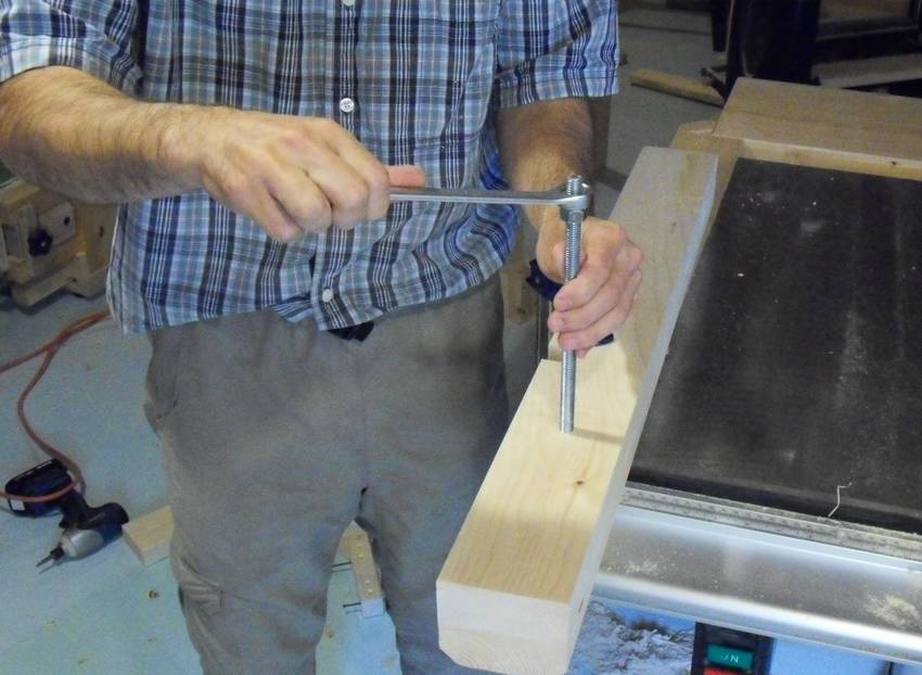 I screwed some plain threaded rod into this rail for attaching the
frame.
I screwed some plain threaded rod into this rail for attaching the
frame.
 Some nuts on the end of the threaded rod bolt the vertical member of the
frame onto this rail.
Some nuts on the end of the threaded rod bolt the vertical member of the
frame onto this rail.
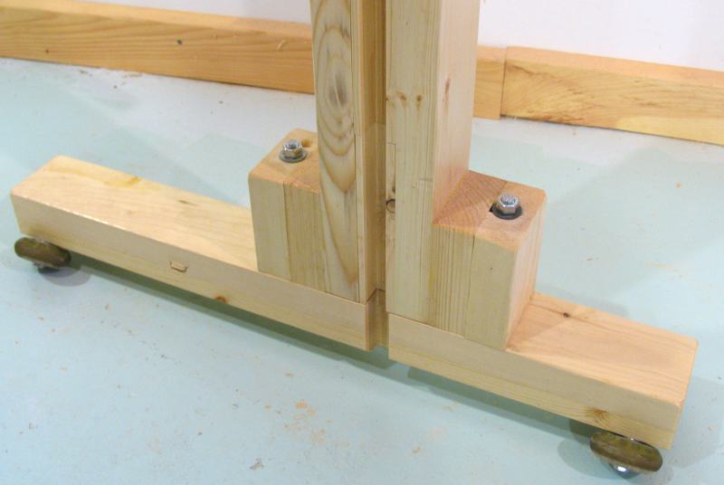
 There is only a single roller blade wheel on the left side of the frame.
This side is meant to just roll on a flat 2x4 on the ground or
directly on a cement floor.
There is only a single roller blade wheel on the left side of the frame.
This side is meant to just roll on a flat 2x4 on the ground or
directly on a cement floor.
A series of holes allows the vertical position of the wheel to be adjusted to compensate whether the left side, right side, or both sides are running on a rail or on the floor.
 The bracket for the left side wheel has a corner joint on it, which I
cut out on the bandsaw. I have had good experience cutting box joints
from paper templates on the bandsaw - it worked well for the
marble machine 2.1 base and
support arm. I will include these
paper templates in the plans.
The bracket for the left side wheel has a corner joint on it, which I
cut out on the bandsaw. I have had good experience cutting box joints
from paper templates on the bandsaw - it worked well for the
marble machine 2.1 base and
support arm. I will include these
paper templates in the plans.
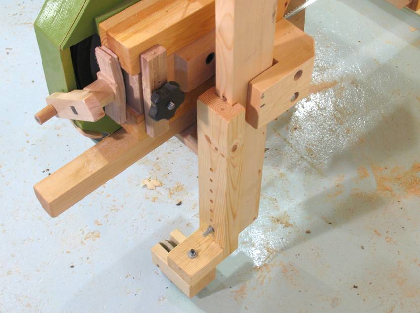
 I attached a rail to the bottom of the bandsaw. This rail slides
in the slot I cut into the right side post of the frame.
I attached a rail to the bottom of the bandsaw. This rail slides
in the slot I cut into the right side post of the frame.
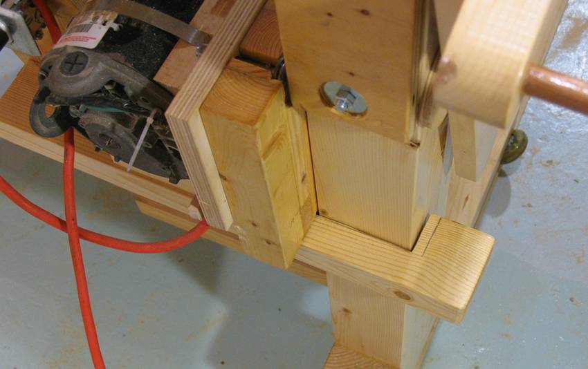 Another bracket hooks around the post to hold the bottom of the
saw against the post.
Another bracket hooks around the post to hold the bottom of the
saw against the post.
Conveniently, the 2x4 that I used for this had a knot right where this part hooks around. That knot acts like a reinforcing dowel, so that end of it will never split off.
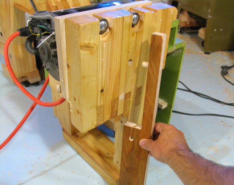
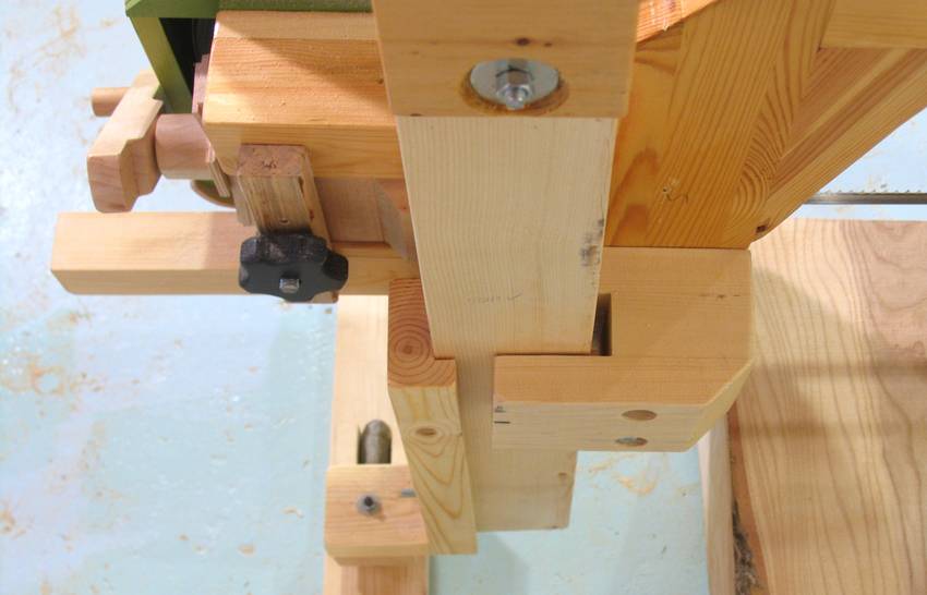
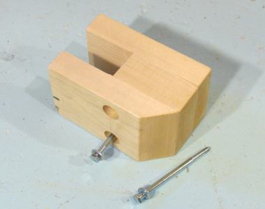
 Here you can see how the bracket that hooks around the post is attached
to the bandsaw. Two dowels (not visible in photo)
keep it aligned, and a single
machine screw and threaded insert hold it in place.
Here you can see how the bracket that hooks around the post is attached
to the bandsaw. Two dowels (not visible in photo)
keep it aligned, and a single
machine screw and threaded insert hold it in place.
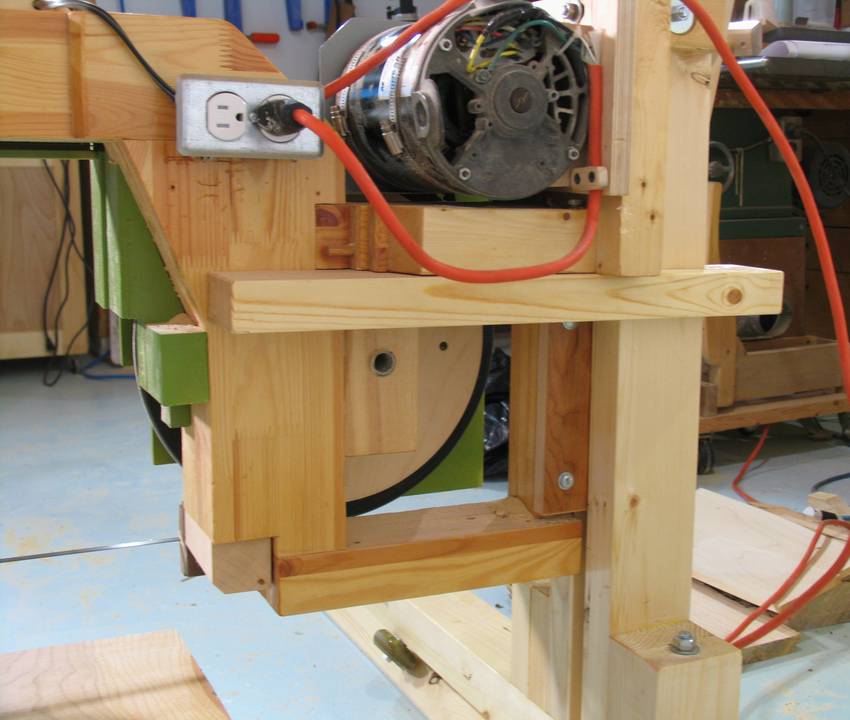
 I made another bracket to attach to the top part of the frame. This guides the
top of the saw against the left leg of the frame.
I made another bracket to attach to the top part of the frame. This guides the
top of the saw against the left leg of the frame.
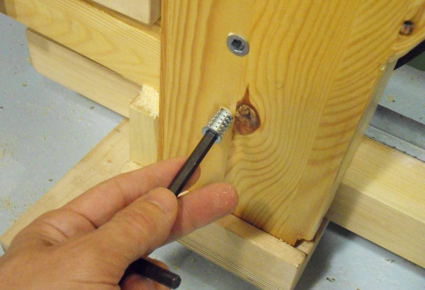 I could have just used long wood screws to attach this part, but so far, I had
attached all the other removable parts with machine screws.
So I used some threaded inserts and machine
screws to attach this bracket as well. That way, I don't wear out the threads in
the wood from switching between sawmill and bandsaw mode.
I could have just used long wood screws to attach this part, but so far, I had
attached all the other removable parts with machine screws.
So I used some threaded inserts and machine
screws to attach this bracket as well. That way, I don't wear out the threads in
the wood from switching between sawmill and bandsaw mode.
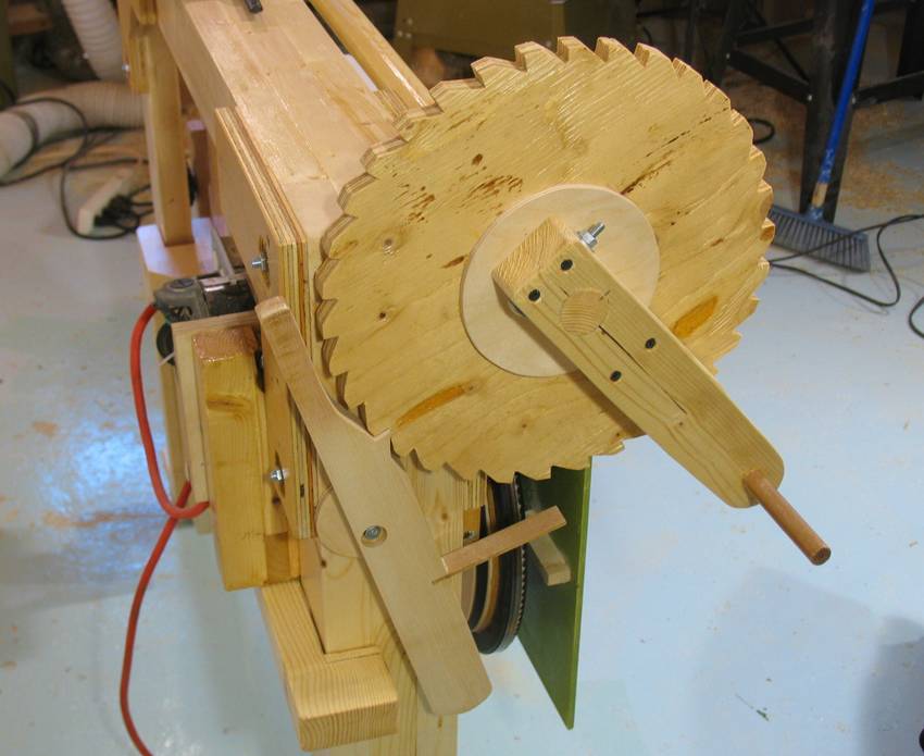 Next I needed some means of moving the bandsaw up and down on the frame.
I built a sort of hand-cranked winch for this purpose.
Next I needed some means of moving the bandsaw up and down on the frame.
I built a sort of hand-cranked winch for this purpose.
 I needed a dowel of a bit less than 1.5" diameter. This dowel didn't need
to be super accurate, and rather than take another trip to the store, I decided
to make my own. I started by cutting an octagonal rail on the table saw,
then rounded the corners with a hand plane. I used a piece of wood with a
hole in it to periodically check the fit.
I needed a dowel of a bit less than 1.5" diameter. This dowel didn't need
to be super accurate, and rather than take another trip to the store, I decided
to make my own. I started by cutting an octagonal rail on the table saw,
then rounded the corners with a hand plane. I used a piece of wood with a
hole in it to periodically check the fit.
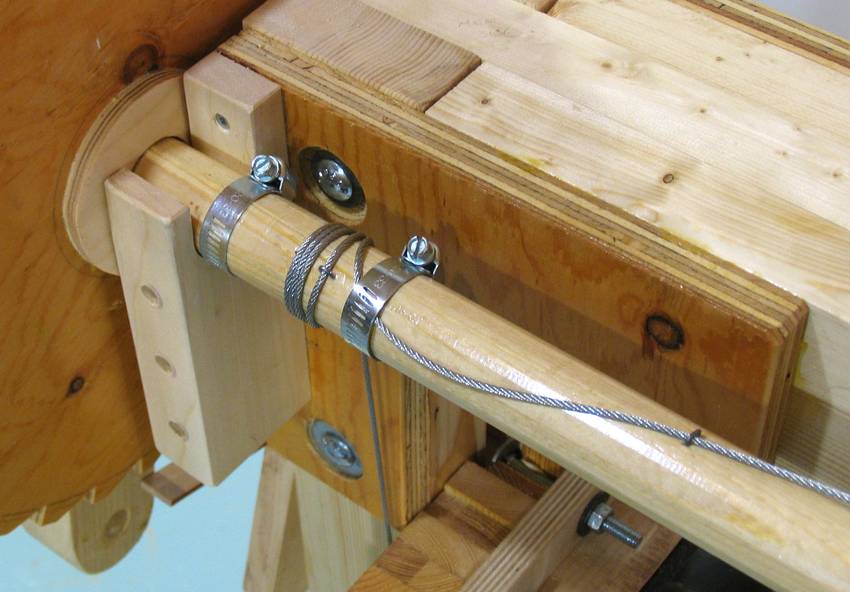 I had initially experimented with some synthetic strands from packing crates
to winch the bandsaw up and down, but then switched to steel cable. The advantage
of steel cable is that it will wind up in turns side by side so that the
amount of elevation per tooth on the sprocket is constant. But the steel cable is
much more difficult to handle. It has a mind of its own and always wants to
straighten out. So the packing crate strands may have been a better idea.
I had initially experimented with some synthetic strands from packing crates
to winch the bandsaw up and down, but then switched to steel cable. The advantage
of steel cable is that it will wind up in turns side by side so that the
amount of elevation per tooth on the sprocket is constant. But the steel cable is
much more difficult to handle. It has a mind of its own and always wants to
straighten out. So the packing crate strands may have been a better idea.
Hose clamps worked out well for holding the cable (or the strand) in place. I make sure there are at least two turns of the cable around the dowel even when the saw is in its lowest position. The friction of the cable around the dowel means that, after two turns, the hose clamp only needs a minimal amount of hold to keep the cable from slipping.
I also added some "staples" to help hold the cable in place. These staples were made by cutting the head off a finishing nail and bending it into a U-shape.
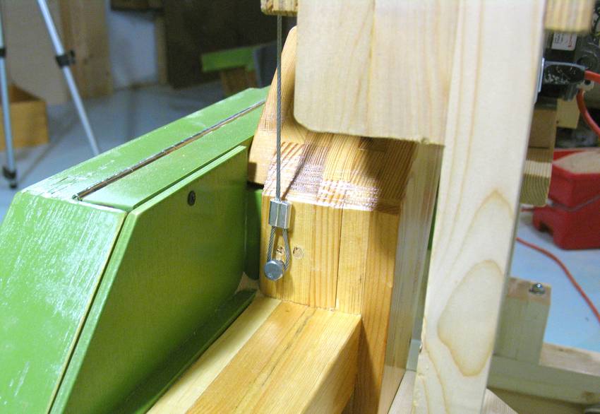 Loops on the end of the cable hook onto the saw.
 Adjusting the relative lengths of the cables turned out to be a finicky affair.
The bandsaw mounts in the frame so that it easily "racks" if one cable is shorter
than the other. I figured this would be a good safety feature if one of the cables
should let loose for some reason. But being off by even half a centimeter on
one side can be problematic.
Adjusting the relative lengths of the cables turned out to be a finicky affair.
The bandsaw mounts in the frame so that it easily "racks" if one cable is shorter
than the other. I figured this would be a good safety feature if one of the cables
should let loose for some reason. But being off by even half a centimeter on
one side can be problematic.
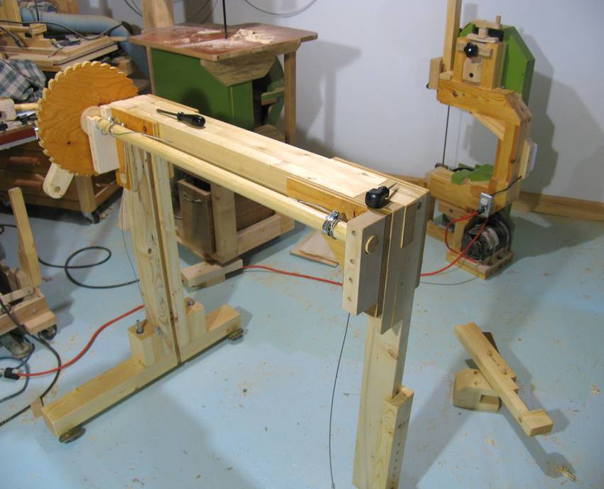
 Here's the saw, on tracks. As it turned out, the rubber wheels gripped well
enough even on my painted basement floor that I could use the saw without rails.
Though with the rails, the saw stays aligned. Also, sawdust can slide
off the rail so that the wheels don't run on a layer of sawdust.
Here's the saw, on tracks. As it turned out, the rubber wheels gripped well
enough even on my painted basement floor that I could use the saw without rails.
Though with the rails, the saw stays aligned. Also, sawdust can slide
off the rail so that the wheels don't run on a layer of sawdust.
The tracks are also useful when operating on uneven surfaces such as grass.
Next: Sawmilling with this bandsaw