|
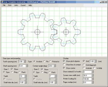
Gear template generator helpThe gear template generator is a program to calculate and print gear shapes for involute spur and pinwheel gearing. |
Gear type and properties
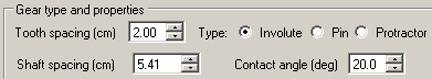
Tooth spacing
Specifies the center to center tooth spacing, as measured along the gear's pitch diameter.
Type
This selects what type of gear teeth to draw. The gear's teeth can be spur, pinwheel, or protractor.
Involute
This specifies involute spur gears. Involute spur gears are the most commonly used type of gear. Any two gears that have the same tooth spacing (or pitch) and the same contact angle (also known as pressure angle) will mesh and run smoothly.
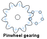
Pinwheel
For some applications, it is desirable that one gear be comprised of just a ring of pins. Such a gear has the pins held together by a disc of sorts that is not in the plane of the gear, and it may or may not have a shaft passing through its center.
The primary advantage of this type of gear is that it's possible to make gears with as few as three teeth that will still run smoothly.
For pinwheel gearing, the gear on the right will always be the pinwheel and the gear on the left will always be shaped to mate with the pinwheel.

Protractor
Sometimes it's useful to be able to create a template that divides a circle into a specific number of intervals. For example, to divide a circle into 23 equal parts with a protractor would be tedious and error prone. Using this program you can just print a template that divides the circle as specified.
Shaft spacing
This field always displays the calculated shaft spacing value. The shaft spacing is the sum of the pitch radii of both gears. Pitch radius is calculated from the pitch circumference. Pitch circumference is the number of teeth times the tooth spacing.
You can also enter a new value in this field and the gear's tooth spacing will automatically be calculated to produce the desired center to center distance for the two gears.
Contact angle
This field specifies the contact angle, also known as pressure angle, for involute spur gears. Larger pressure angles produce gears that have more triangular looking teeth. Larger pressure angles work better for gears with a small number of teeth, but the overall result is lower efficiency due to higher friction in the gear set.
This field is only applicable for involute spur teeth and is hidden if other types of gear teeth are selected.
Pin diameter
This field specifies the size of the pins for pinwheel gearing. This field is only applicable to pinwheel gearing and is hidden if other types of gear teeth are selected.
Gear properties
 This section allows you to specify the parameters specific to each gear.
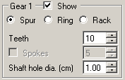
Show
Selects whether the gear is visible. Note that for pinweel gears, the properties of the pinwheel affect the shape of the mating gear, so even if the right gear is hidden, its properties still affect the gear on the left.
Spur
Selects a regular spur gear. That is, a round gear with teeth on the outside.
Ring
Selects a ring gear. A ring gear is a gear with teeth on the inside. Ring mode can only be selected if the other gear is a spur gear.
Rack
Selects a "rack" type gear. A rack is essentially a gear that has been unwrapped. Rack and pinion mode is only currently available for involute tooth types.
Teeth
Specifies the number of gear teeth.
Spokes
Specifies the number of spokes. Only spur gears above a certain number of teeth are large enough to have spokes.
Shaft hole diameter
Specifies the shaft hole to draw. For pinwheel gearing, this specifies the size of the shaft in the middle of the pinwheel. Gear teeth on the left side gear will be kept short enough so as not to interfere with the pinwheel gear's center shaft. Specify zero to omit the center shaft or shaft hole.
Display parameters
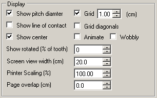
This part of the panel selects which aspects of a gear to display.
Show pitch diameter
When selected, a circle is drawn indicating the gear's pitch diameter.
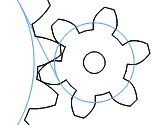
Show line of contact
For involute teeth, this shows the contact angle (pressure angle) and base radii of the two gears. If you think of the base radii as being two spools, a point along a string unwound from the right gear's base radius and wound onto the left gear's base radius would exactly follow the path along which both gears touch.
Show center
Show a crosshair in the center of each gear.
Grid
Draw a grid. The grid is useful for getting a sense of scale, for checking that a printout was scaled correctly, and to help align multiple pages together when pasting together multi-page printouts.
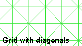
Grid diagonals
Draw diagonal lines on the grid. Diagonal lines are very useful to help align the sheets of a multi-page printout when gluing the pieces of paper together.
Animate
Slowly turn the gears. This allows you to examine how the gears mesh. Note that spur gears with less than 10 teeth and low contact angles will often cause interference. For gears with very few teeth, try pinwheel gears.
Wobbly
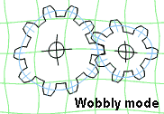
I implemented "wobbly mode" for the evaluation version of the program. The eval version can do everything the full version can do, but all output is distorted. The distorted gears would not work in real life.
I found the distorted "wobbly mode" fun to watch, so I have added this "feature" as an option to the full version as well, just for fun.
Show rotated
This field causes the gears to be displayed rotated. The angle is specified as one hundredths of a tooth. Specifying 25, for example, will cause the gears to be rotated by one quarter tooth interval.
This feature is useful if you want to check that spur gears mesh without interference. It's especially useful if you use the up/down buttons, and zoom in on the meshing point by reducing the value of the "screen view width" field.
Screen view width
This field indicates how wide an area the screen represents. This value defaults to 20 cm, or about the width of the printable region on a normal piece of paper.
Note that this value is in whatever units you chose. If you change the units to "inches" then the visible region would change to 20 inches, along with all other dimensions. The display would not change, but when you print it, it will now be much larger as it's now sized in inches.
Printer scaling
You may find that your printer prints just slightly larger or smaller than it should. If you find that 10 grid lines of a one centimeter grid are actually 10.1 cm, you can compensate for this by telling the gear generator to scale output to 99%.
Page overlap
If you print gears that span multiple pages, the gears are printed with no overlap. You may prefer to have a slight amount of overlap from page to page, to give you more confidence in aligning the pages. Use this field to specify that you want overlap.
You may also find that its quite easy to align the pages even without overlap when grid diagonals are enabled.
Saving
The parameters for a gear can be saved in a file for later reloading. The parameters are simply stored in a text file. If a file called "default.gear" exists in the same directory as the program, it will be loaded automatically when the program starts.Printing
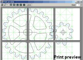 The gear template generator is able to print gears that span many pages.
If a gear does not fit onto a single page, then the gear is split across a range
of pages to be printed and then glued together.
The gear template generator is able to print gears that span many pages.
If a gear does not fit onto a single page, then the gear is split across a range
of pages to be printed and then glued together.
Grid lines, especially when combined with diagonal grid lines, are very useful to help precisely align the pages when gluing them together.
It's advisable to do a print preview before printing your gears. The dimensions you have specified might result in gears that span a surprisingly large number of pages.
Exporting
When exporting to a file, everything that is drawn on the screen is exported. This included both gears, as well as any center and grid lines you may have turned on. It's recommended that you turn off everything but one gear and its center crosshair before exporting. Otherwise, it can be difficult to separate the gears from the grid in whatever program you are importing into.No printer pagination will be applied to export.
 in Google SketchUp |
DXF (for CAD)
Most CAD programs can import DXF files. DXF is a format that AutoCAD standardized as a means of interchanging 3D graphics. The gear template generator's DXF export is relatively simplistic and only two dimensional, but it will get the shapes into your CAD program.The DXF export does not include units. Programs that import DXF typically allow you to specify which units the DXF file actually uses. For example, if you used inches to design your gear, but the importing program assumes the units are millimeters, the imported gear will be much smaller than you expect.
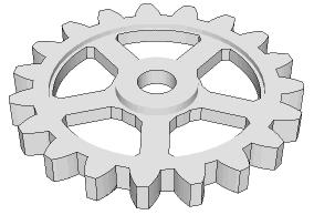
SketchUp
One of the most popular CAD programs among woodworkers is the free Google SketchUp. However, the free version of SketchUp does not handle DXF import. It does, however, import data in "Collada" format. Because so many people use the free version of SketchUp, I implemented export to this format so that you can still import gears into the free SketchUp. As CAD programs go, SketchUp is relatively easy. But be warned. All CAD programs have a steep learning curve.When you import a gear into SketchUp, it will be imported as nested objects. Keep opening the objects until you have opened the gear outline. To turn the outline into a surface that can be extruded, draw a rectangle around the whole outline, then delete the outline of the rectangle. If your gear has spoke and center holes, select these with a double click, copy them, delete them, then paste them in place. After that, you will be able to delete the surface inside the spoke holes. I don't think SketchUp works as well as they say it should in this particular regard, but the above procedure has worked for me.
HPGL
HPGL stands for Hewlett Packard Graphics Language. It is the format used by the old HP plotters. Nobody uses plotters anymore, but the format is fairly straightforward and various pieces of software still know how to import and export graphics in this format. I tested HPGL exporting against this HP plotter emulator.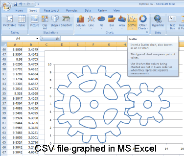
CSV (for spreadsheet)
CSV (Comma Separated Values) is the simplest form of export, consisting of just two columns of numbers, plus some annotation. This format can be loaded into spreadsheets such as Excel. You can display the gears as a graph in Excel by selecting the two columns of numbers and generating an X-Y scatter graph from the data.Displaying gears in a spreadsheet is not particularly useful, but it's a good starting point if you wish to manipulate the X-Y points in some way for your own purposes.
Units
Units can be selected to be inches, centimeters or millimeters. Note that the displayed gear's size does not change if the units are changed. A gear that is 10 cm across, when you change the units to inches, will now be 10 inches across. The screen width would also change from 20 cm to 20 inches. However, on printing or exporting, the gears will be scaled accordingly. Note, however, that on importing DXF, the units are not specified inside the file. Typically, one must indicate to the importing program what units are represented in the file.
Any other questions?
If you have any questions about the gear template generator that this Help doesn't answer, feel free to email. Feedback is always appreciated. My email address is:Back to the Gear template generator