I had originally written a Shorter article for my website. This article is on a refined version of the design that I built while writing the article for woodcraft magazine.
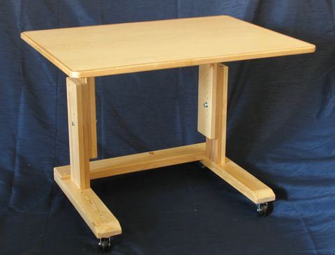
This table design is intended to allow for working in unusual seating positions. I originally came up with this concept when I wanted to work from remotely from my girlfriend's place in another city. I wanted a table that I could be set up to be ergonomic with any seating opportunity I could find. I also wanted to be able to wheel the table out of the way and into a spare room while not in use.
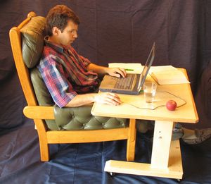 After I built it for that purpose, I found it to be very comfortable to use
with a computer in combination with a couch or easy chair at my own house. So I built
another one, which I have been using as my main computer table ever since. The idea
is to sit down on a couch or easy chair, pile pillows behind myself until comfortable,
and pull the computer up to me.
After I built it for that purpose, I found it to be very comfortable to use
with a computer in combination with a couch or easy chair at my own house. So I built
another one, which I have been using as my main computer table ever since. The idea
is to sit down on a couch or easy chair, pile pillows behind myself until comfortable,
and pull the computer up to me.
You will also need a 1"x6"x8" piece of oak for the vertical adjusting slides, another 1x3x6 piece for the trim around the top, and a piece of veneered plywood, 2'x3', and about 1/2" thick. Also, some 3/8" bolts, four 2" castors, and a lot of 1.5" #8 wood screws.
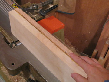
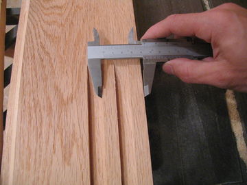
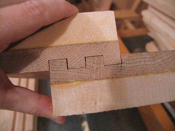
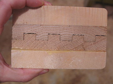
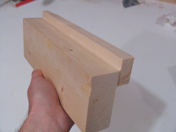
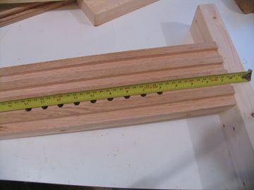
When measuring for cutting the grooves, consistent spacing is very important. If you measure to the blade, mark the tooth that you measure to with a permanent marker. If one of the slots is out by 1/64 of an inch, the grooves may not fit into each other. Proceed by making the next two cuts by again moving the fence away from the blade by 1 3/8" of an inch. The last grove you cut should just cut the rest of the piece away. The final pieces should fit together as seen in Fig 6.
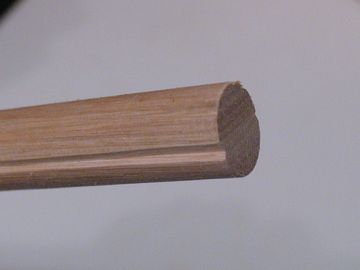
Next use a 1/4" radius router bit to round the outside edges (the spruce parts) along the length of the piece.
The bevel should be about 30 degrees. Next we attach the grooved pieces into the horizontals of the legs and table supports with 4/8" dowels. First cut a small grove into the 5/8" dowel to allow for the glue to escape (Fig 8) , then cut 8 pieces of dowel 4.25" long
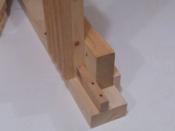
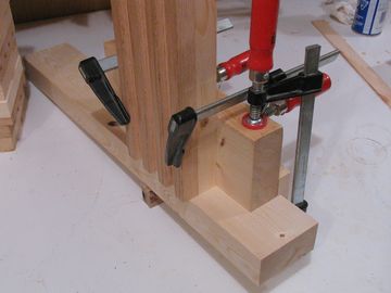
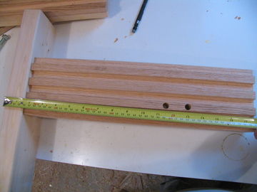
Cut another piece of wood, about 1"x1" by exactly 4" long. This piece will be used to ensure that the upright is attached 4" from the end of the table support, as shown in Figure 10 - it's the piece with the two nail holes.
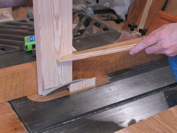
Use the large guide piece to align the upright on the table support.
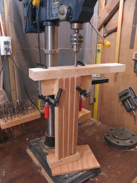
The centers of the holes should be aligned to go into the middle of the solid (ungrooved) portion of the upright, and with centers about 5/8" from the edges.
Drilling the holes straight through both pieces avoids any subsequent alignment problem when joining the parts with dowels.
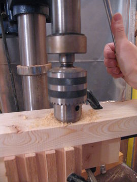
Next remove the horizontal table support piece, but leave the block clamped to the upright. Unless you have a very long 5/8" drill, your holes will not be deep enough, so drill them to a full depth of 2.5 inches after removing the table support part.
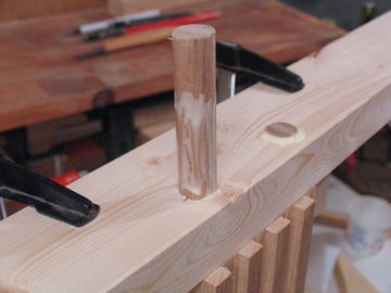
Next clean any shavings from the holes, and apply glue to the end of the upright and the mating surface of the table support. Then put the piece back in place, using the block clamped to the upright as a guide, as well as the 4" long piece of scrap to align it the same way it was before, so that the holes line up.
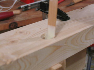
Next use a thin scrap of wood to apply glue to the inside of the hole (Fig 14) and also to the dowel. Insert the dowel in the hole. Ideally, the dowel fits rather tightly and needs a mallet to drive in (Fig 15)
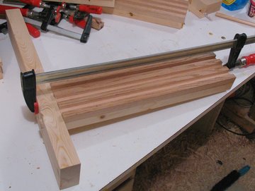
Use the same approach for the other upright and table support, making sure they are mirror images of each other.
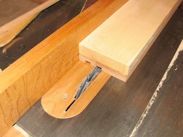
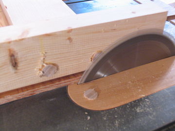
After the glue has dried, cut the dowels flush with a table saw (Fig 17)
Next assemble the leg pieces. These are just like the table supports, with the difference that the legs are a bit wider. We can use the same guide block for the legs as well. Be very careful that you put the uprights on the legs with the grooved pattern facing the opposite way, so that they will mate with the grooved pieces of the uprights. That is, other than the horizontal part being a little larger, the grooves / slots of the uprights should be a mirror image of those joining the table supports, so that they will mate correctly when you put the table together.
Drill these holes nearer to what will be the front of the table. Because the center of mass of the load on the table is likely to be forward of the leg uprights, this will relieve a bit of bending load on the grooved joints.
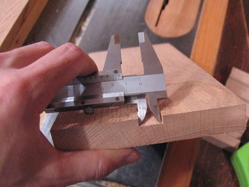
In the uprights attached to the legs, drill two holes, 1.5" apart, one 11.5" from the bottom of the leg and the other 13" from the bottom of the leg (Fig 19). Make these a little larger - 7/16th in diameter, to allow for a bit more room.
By making the holes in the parts attached to the legs 1.5" apart, it is subsequently possible to adjust the height by 1/2" increments by changing which of the two holes in the upright the bolt is passed through.
Next... Putting it together and making the table top
To my Woodworking website
![]()