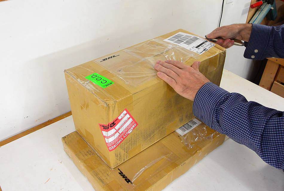
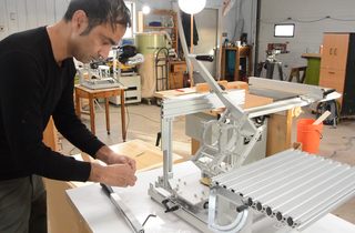
 I previously wrote about assembling
the "hybrid pantorouter" in 2013, but since then,
there is a new tilting table option, and a number of minor things have
changed, so this is an updated assembly guide.
I previously wrote about assembling
the "hybrid pantorouter" in 2013, but since then,
there is a new tilting table option, and a number of minor things have
changed, so this is an updated assembly guide.
I previously wrote about assembling
the "hybrid pantorouter" in 2013, but since then,
there is a new tilting table option, and a number of minor things have
changed, so this is an updated assembly guide.
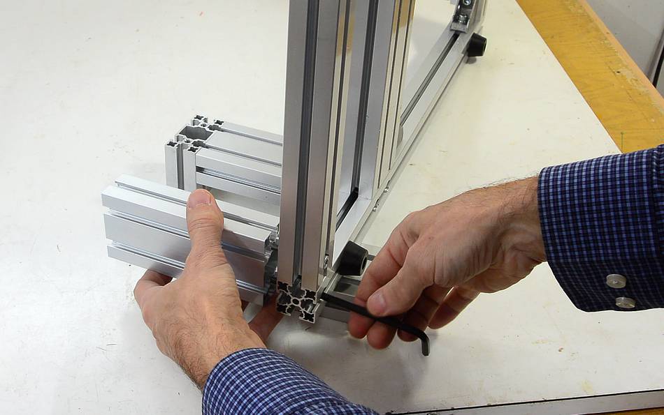
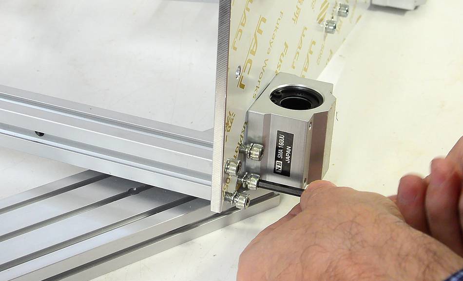
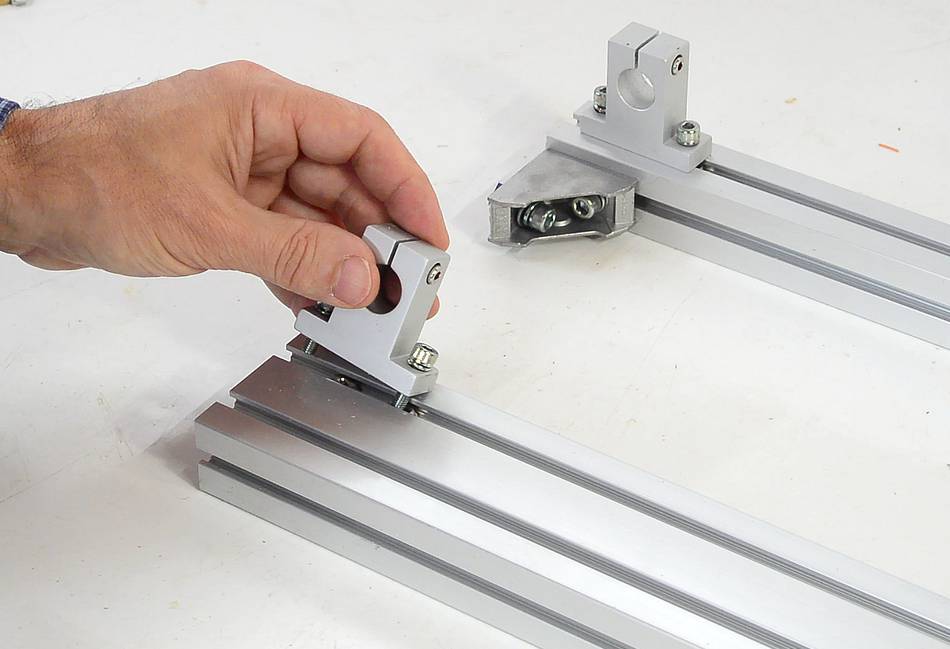 The cross pieces of the frame need angle brackets and shaft holders
mounted to them. These are screwed on by inserting square nuts into the
rails and screwing into those.
The cross pieces of the frame need angle brackets and shaft holders
mounted to them. These are screwed on by inserting square nuts into the
rails and screwing into those.
It's best to snug the screws slightly, just enough to keep the pieces from sliding around, but not tight.
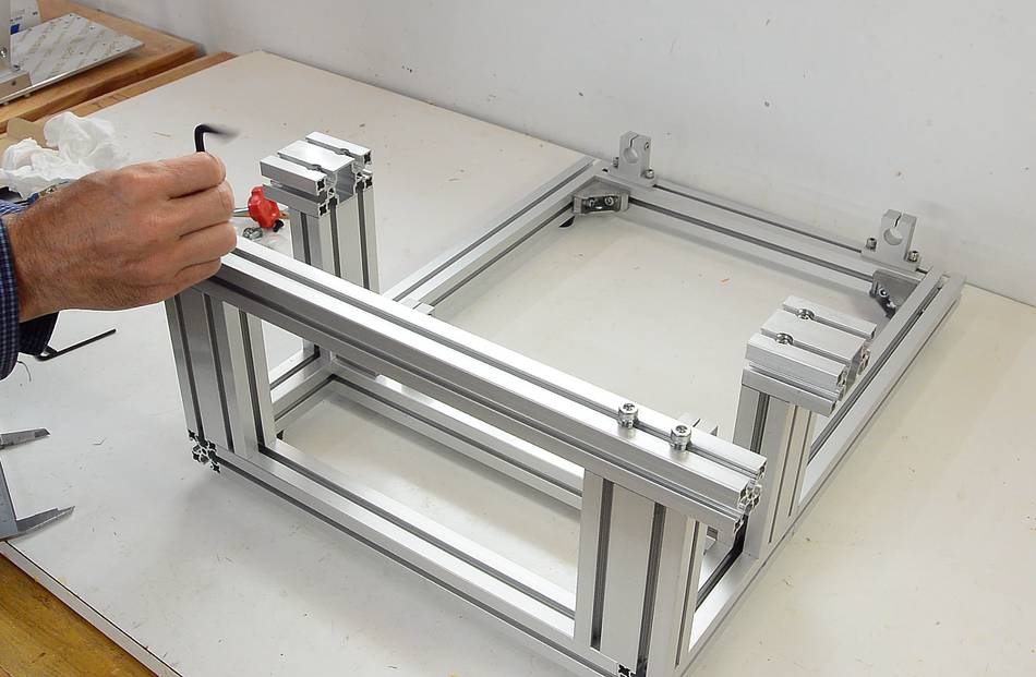
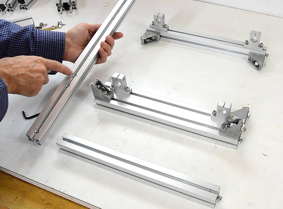 The three cross pieces go in this arrangement, with a long rail on either side.
The long rail has some holes that need to face down. The wide middle cross piece mounts where the holes I'm pointing to are. There is a line on the rail to indicate the position.
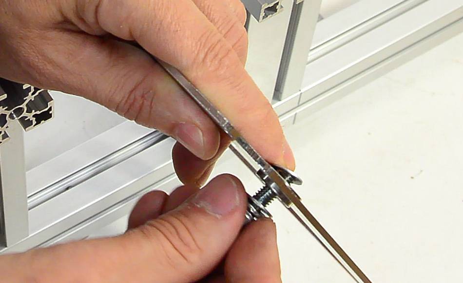
 The long rails attach with screws in the ends of the short rails. The screws slide
into the slots in the rails. The screws have washers. These washers need
to go into the slot
The long rails attach with screws in the ends of the short rails. The screws slide
into the slots in the rails. The screws have washers. These washers need
to go into the slot
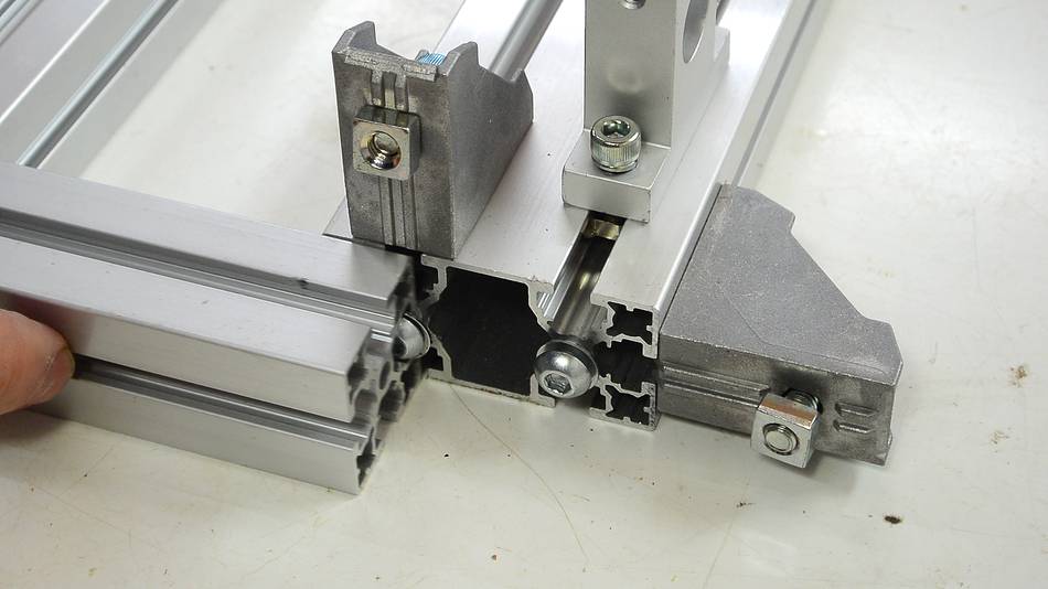
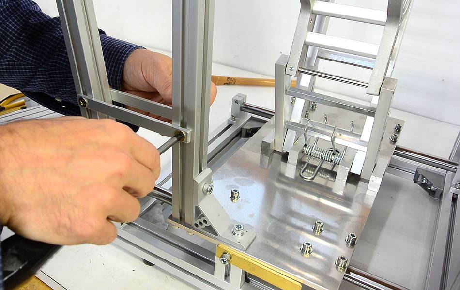
 The long rails have holes where the cross pieces attach. An Allen key can
be used to tighten the screws through the holes.
The long rails have holes where the cross pieces attach. An Allen key can
be used to tighten the screws through the holes.
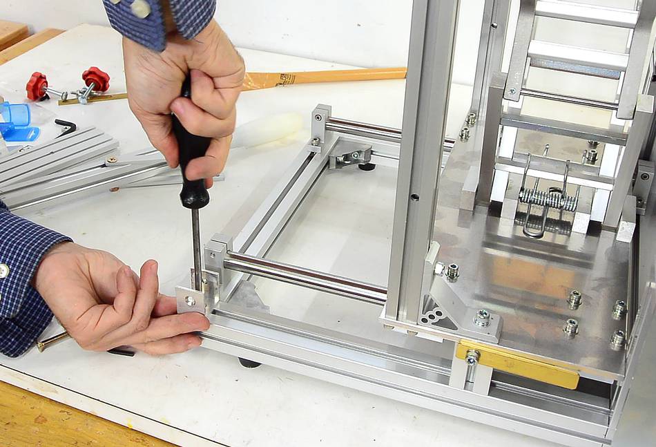
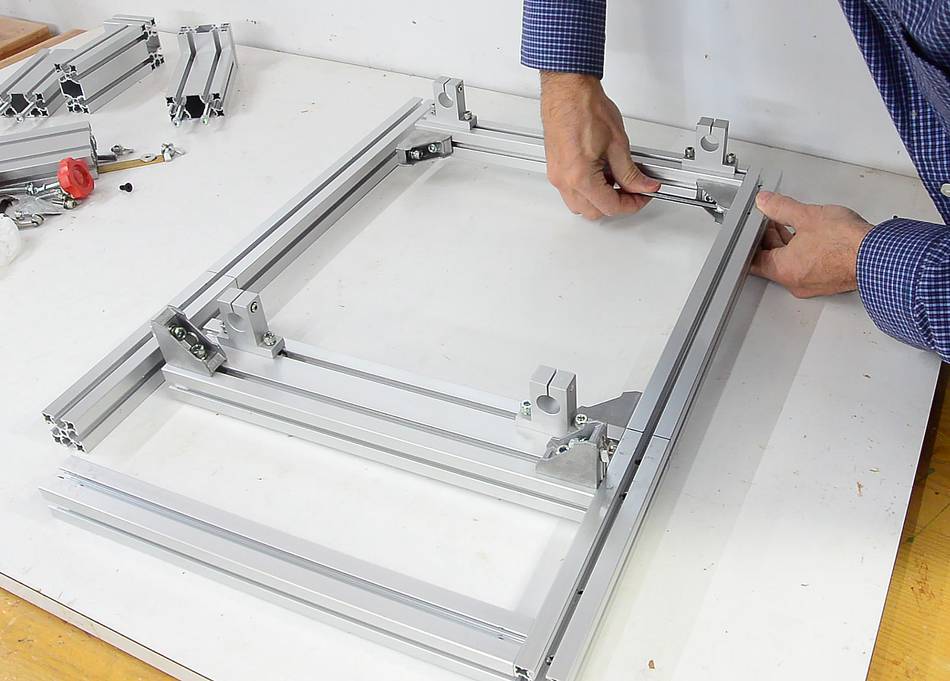 Next tightening the angle brackets. Make sure they are slid all the way
into the corners before tightening.
Next tightening the angle brackets. Make sure they are slid all the way
into the corners before tightening.
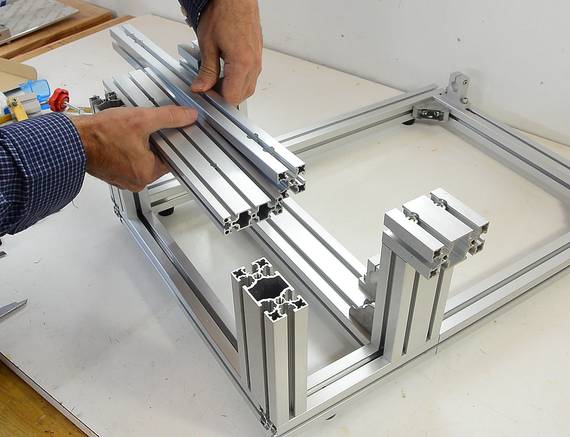
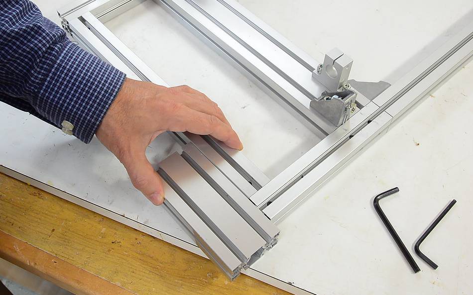 You can use one of the other extrusions to make sure the
rails are flush with the ends.
You can use one of the other extrusions to make sure the
rails are flush with the ends.
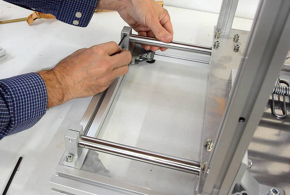
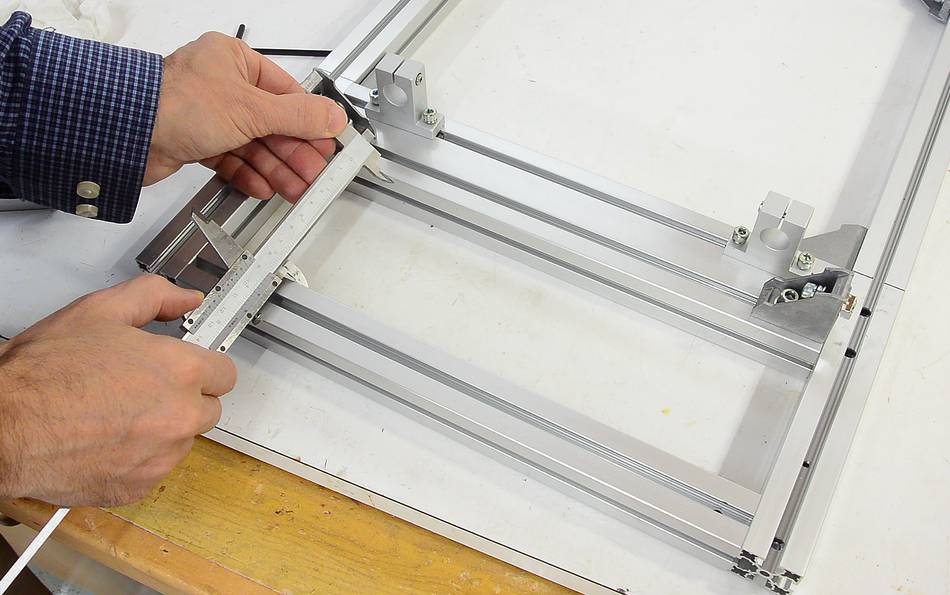 The two rails near the front need to have exactly 90 mm between them.
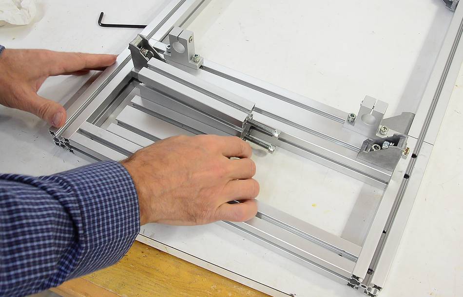 If you don't have callipers handy, you can use two of the extrusions
(one 30 mm, the other 60 mm) to set the 90 mm space before tightening
the screws.
If you don't have callipers handy, you can use two of the extrusions
(one 30 mm, the other 60 mm) to set the 90 mm space before tightening
the screws.
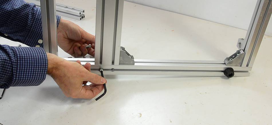
 Now is the best time to attach the rubber feet. These screw
into the long rails on the bottom with the thin long screws provided.
Now is the best time to attach the rubber feet. These screw
into the long rails on the bottom with the thin long screws provided.
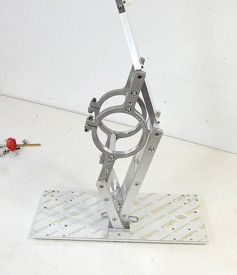
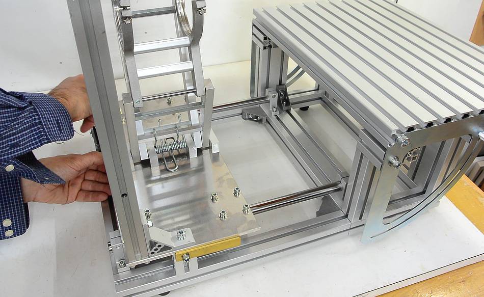
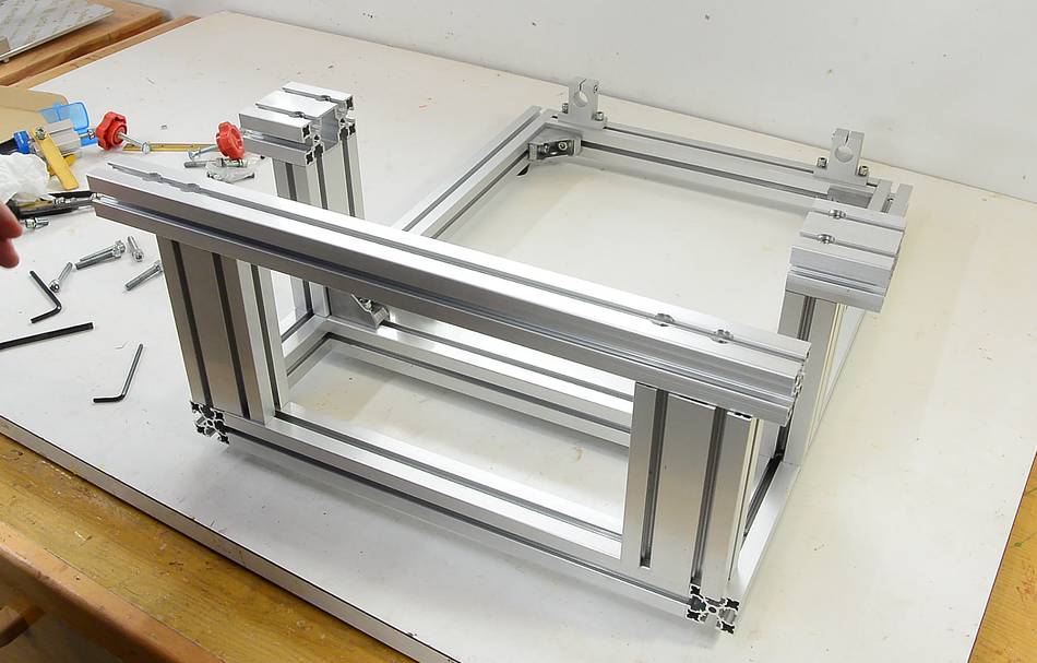 This is how the table supports go together.
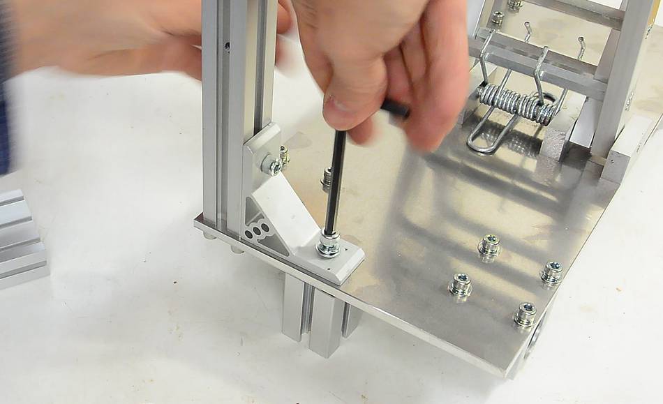
 The extrusions are screwed onto the bottom of the frame with the large
cap screws. Before you screw these on, make sure you have the cross
pieces where you want them and the screws tightened, because you will not
be able to access these screws once the large screws are in.
The extrusions are screwed onto the bottom of the frame with the large
cap screws. Before you screw these on, make sure you have the cross
pieces where you want them and the screws tightened, because you will not
be able to access these screws once the large screws are in.
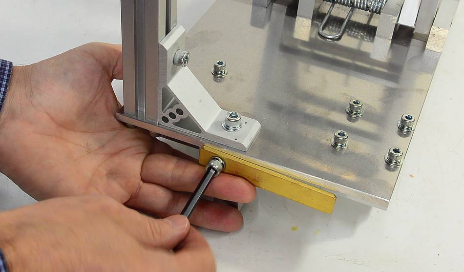
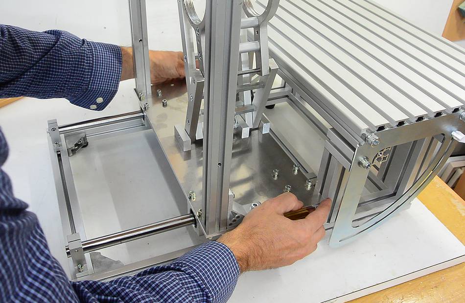
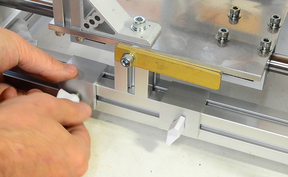
 A long cross-piece screws on at the front, again with the large cap screws.
It's important to make sure the spacing between the rail on the front and the L-shaped parts in the back is 90 mm. At this point, the short 60 mm wide extrusions are all used up. If you have the optional Bessey clamp, you can use the 60 mm wide extrusion that came with that. Otherwise, you can use the extrusions of the template holder (25 mm + 25mm + 40 mm = 90 mm)
If it's off by 0.5 mm, you will run into problems later. You may have to loosen the screws and wiggle the parts one way or the other. Sometimes it helps to flip the vertical pieces near the front end-to-end to get the spacing just right.
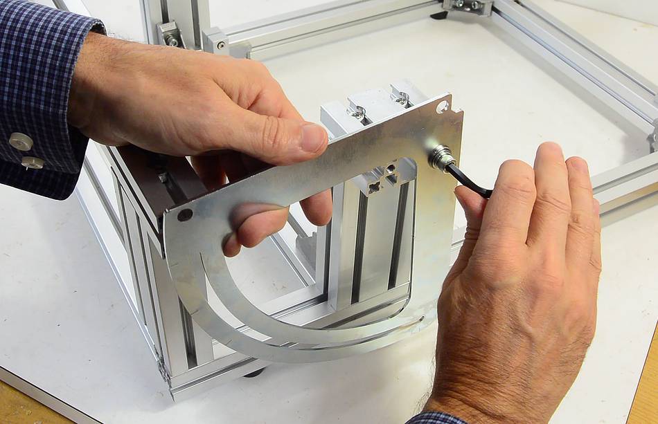
 The protractor for tilting the table screws to the ends of the L-shaped posts.
These attach with a screw. The bearing has a wider flange on one side. This needs
to face towards the L shaped piece. A small washer needs to go between the bearing
and the extrusion so that the bearing isn't jammed when the screw is tightened.
The protractor for tilting the table screws to the ends of the L-shaped posts.
These attach with a screw. The bearing has a wider flange on one side. This needs
to face towards the L shaped piece. A small washer needs to go between the bearing
and the extrusion so that the bearing isn't jammed when the screw is tightened.
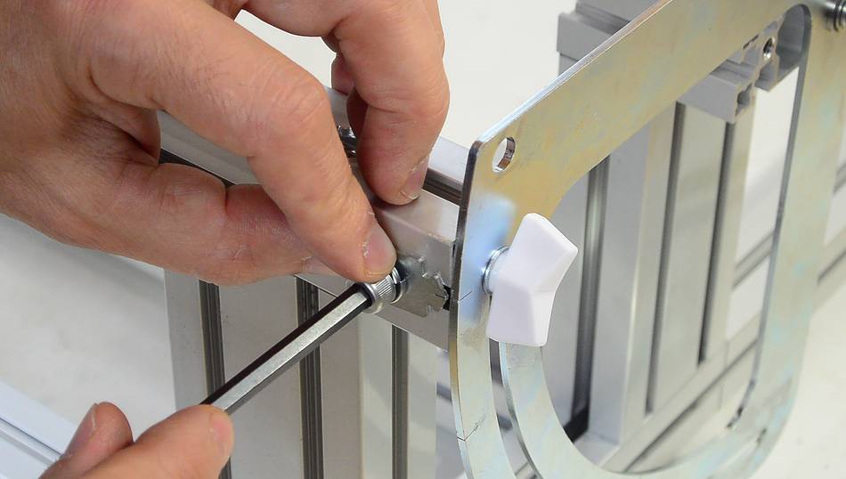
 The protractor locks with a knob that screws into the end of the long rail.
If the spacing between the two mounts is not 90 mm, you won't be able to get this screw in.
 There is also a pointer for the angle that attaches to the front of the rail.
Install the pointers for either side before installing the second protractor
while you can still slide the nuts in from the other end.
There is also a pointer for the angle that attaches to the front of the rail.
Install the pointers for either side before installing the second protractor
while you can still slide the nuts in from the other end.
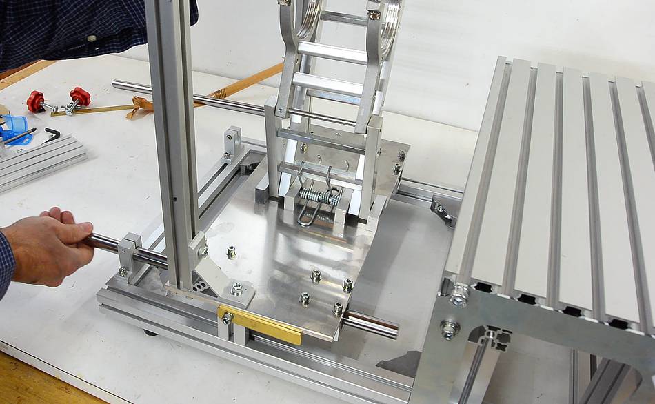
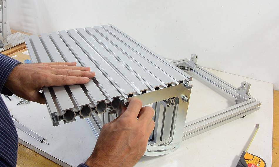 The table mounts between the protractors. Two of the holes in the side have threads
cut into them. The screws go into those holes.
The table mounts between the protractors. Two of the holes in the side have threads
cut into them. The screws go into those holes.
 There are no adjustable stops for level and 90 degrees. With the table all the way
down and resting on the long cross piece, it is already level. The other end of
the range of the protractors is 90 degrees (vertical).
There are no adjustable stops for level and 90 degrees. With the table all the way
down and resting on the long cross piece, it is already level. The other end of
the range of the protractors is 90 degrees (vertical).

 With the base assembled this far, it's time to work on the pantograph.
There may be protective foil on it. Peel it off the top. If is also protective foil on the bottom. I'd recommend just leaving that on.
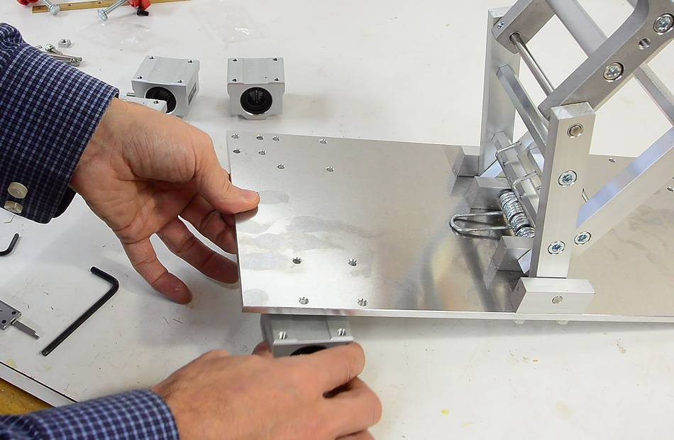 The linear bearings are mounted to the bottom with screws from the top.
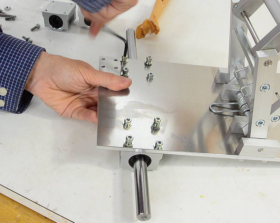 It's a good idea to insert the shaft before tightening the screws to
ensure the bearings are aligned with each other.
It's a good idea to insert the shaft before tightening the screws to
ensure the bearings are aligned with each other.
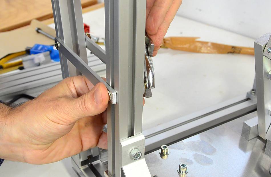
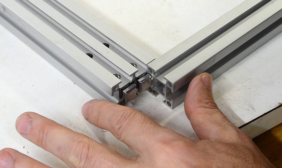 The template holder frame is made of the thinner aluminium extrusions.
The cross piece has two square buttons on the ends. Loosen the screws from
the side, then slide the buttons into the slot in the other extrusion.
The template holder frame is made of the thinner aluminium extrusions.
The cross piece has two square buttons on the ends. Loosen the screws from
the side, then slide the buttons into the slot in the other extrusion.
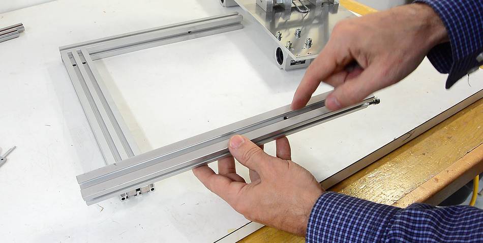 Make sure the rails are oriented so that the hole through the side
points towards the other piece, and the screws (or screw threads) are on
the other end as the cross rail.
Make sure the rails are oriented so that the hole through the side
points towards the other piece, and the screws (or screw threads) are on
the other end as the cross rail.
 Then fasten the frame to the base with screws from below.
 An angle bracket attaches to one side, with a piece of extrusion below that.
The pantograph base has holes for mounting this angle bracket on either side.
For left-handed people it may be advantageous to assemble the pantorouter
as a mirror image. However, you will have to disassemble and re-assemble the
pantograph mechanism in mirror image as well if you do.
An angle bracket attaches to one side, with a piece of extrusion below that.
The pantograph base has holes for mounting this angle bracket on either side.
For left-handed people it may be advantageous to assemble the pantorouter
as a mirror image. However, you will have to disassemble and re-assemble the
pantograph mechanism in mirror image as well if you do.
 Attach the piece of brass for the pointer to the piece of extrusion before
mounting the pantograph onto the base. You will not be able to slide the nut
into the extrusion later.
Attach the piece of brass for the pointer to the piece of extrusion before
mounting the pantograph onto the base. You will not be able to slide the nut
into the extrusion later.
 Loosen the screws on the shaft mounts, then place the pantograph on the base
and slide the shafts through the mounts, pantograph, and other mount.
Loosen the screws on the shaft mounts, then place the pantograph on the base
and slide the shafts through the mounts, pantograph, and other mount.
 With both shafts slid in, slide the pantograph base all the way forward
and make sure it hits both vertical supports for the table, and that the
corners of it are flush with the corners of the vertical supports.
With both shafts slid in, slide the pantograph base all the way forward
and make sure it hits both vertical supports for the table, and that the
corners of it are flush with the corners of the vertical supports.
 Tighten both supports for the shaft nearer to you, then slide the pantograph
all the way back (to the left), tighten the back shaft mount on the
far shaft, then slide it all the way forward and tighten the front shaft mount.
Tighten both supports for the shaft nearer to you, then slide the pantograph
all the way back (to the left), tighten the back shaft mount on the
far shaft, then slide it all the way forward and tighten the front shaft mount.
 Also tighten the small screws in the shaft mounts to lock the shafts in.
 Mount the U-shaped base for the plunge lever in the corner with a screw.
 A long countersink screw mounts the base of the lever. This screw threads into
the bracket. There is no nut on the other side.
A long countersink screw mounts the base of the lever. This screw threads into
the bracket. There is no nut on the other side.
 Mount the two links to the template frame. turn the screw all the way in
(the link on the back has a thread), then back it out a fraction of a turn...
Mount the two links to the template frame. turn the screw all the way in
(the link on the back has a thread), then back it out a fraction of a turn...
 ... and lightly tighten a nut on the opposite side.
 Side two square nuts into the rail from the end and mount the L-shaped depth
stops to the rail.
Side two square nuts into the rail from the end and mount the L-shaped depth
stops to the rail.
 Then glue the scale to the brass bar. The "0" of this scale should line up
with the edge of the stop when the stop is against the vertical extrusion that
the brass bar mounts to.
Then glue the scale to the brass bar. The "0" of this scale should line up
with the edge of the stop when the stop is against the vertical extrusion that
the brass bar mounts to.
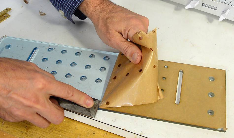 The protective foil needs to be peeled off the template holder.
I found it quite hard to get off.
The protective foil needs to be peeled off the template holder.
I found it quite hard to get off.
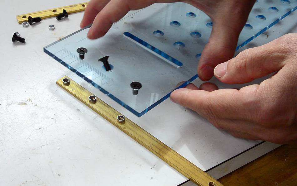 Two brass bars mount to the back of the template holder, with small
ring shaped spacers between the bar and the template.
Two brass bars mount to the back of the template holder, with small
ring shaped spacers between the bar and the template.
I found it easiest to put the spacers on the bar, put the screws in the template holder, then put the template on the bar and tighten the screws.
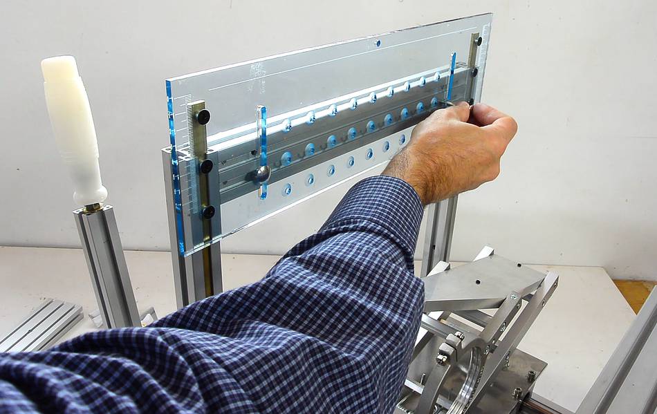 Slide the brass bars into the slots of the template holder. Then insert the
long carriage bolts into the slots.
Slide the brass bars into the slots of the template holder. Then insert the
long carriage bolts into the slots.
The red knobs and washers go on the back of these.
On mine, I found the carriage bolts had a tendency to bind in the slots. I filed a slight chamfer to the edges of the slot on the front side to avoid this.
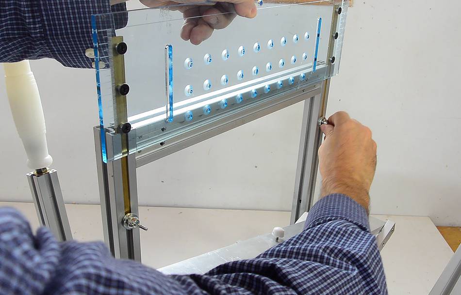 There are also some thumb screws that can be inserted into the bars.
The large dovetail template interferes with the heads of the carriage
bolts, so these are sometimes removed, and the small thumb screws used to fix
the vertical position instead.
There are also some thumb screws that can be inserted into the bars.
The large dovetail template interferes with the heads of the carriage
bolts, so these are sometimes removed, and the small thumb screws used to fix
the vertical position instead.
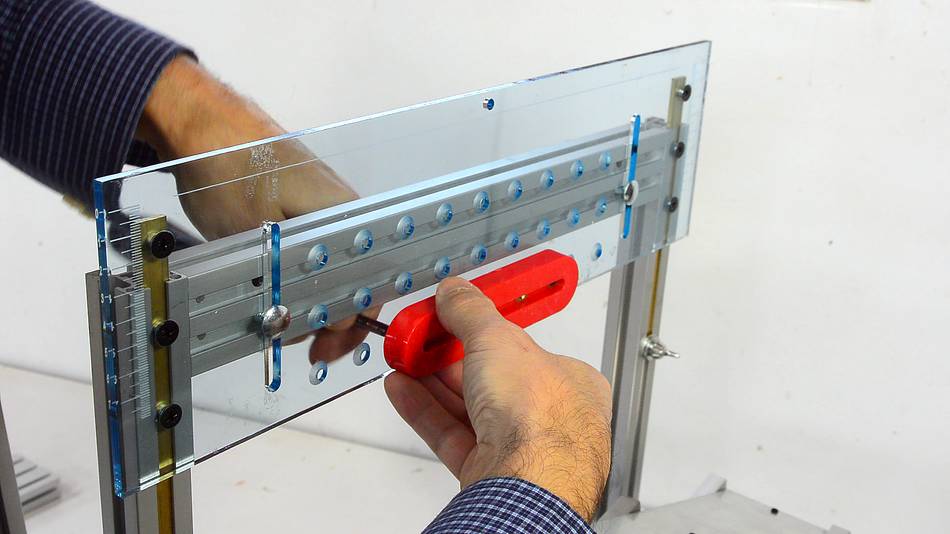
 The included tenon templates screw onto the holder from the back. The follower
traces around this template.
The included tenon templates screw onto the holder from the back. The follower
traces around this template.
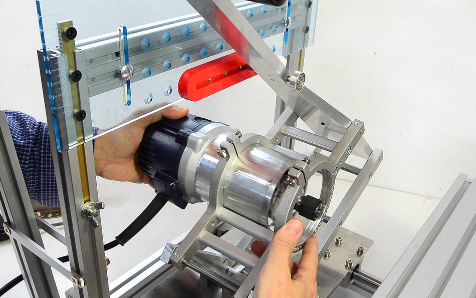 Before inserting the router, loosen the screws on the router mount and
back them out by several turns. The fit can be very snug, and it may be
helpful to smear a drop of oil to the inside surface of the router mount
before sliding it in.
Before inserting the router, loosen the screws on the router mount and
back them out by several turns. The fit can be very snug, and it may be
helpful to smear a drop of oil to the inside surface of the router mount
before sliding it in.
Ideally, the gap where the screws are about 2 mm once the router is installed and the screws tightened.
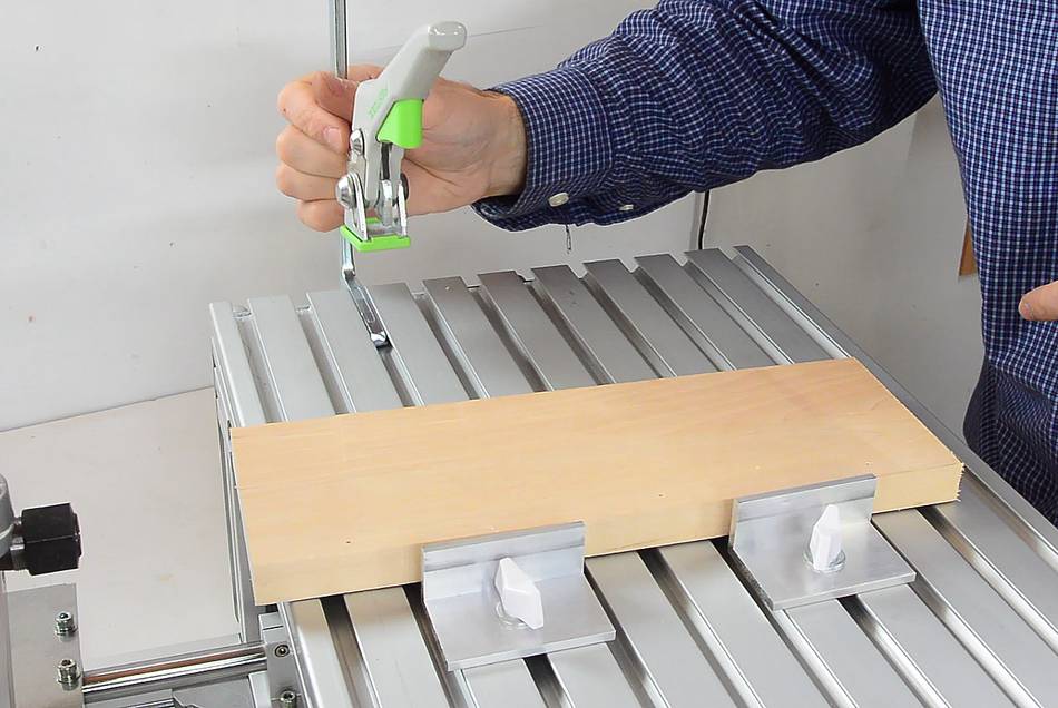
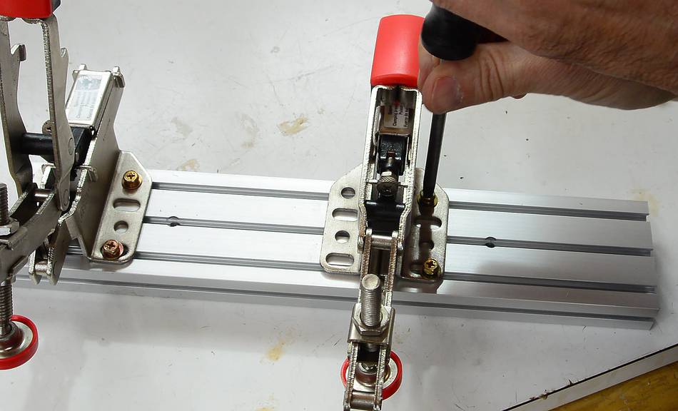 If you also ordered the optional Bessey hold down clamps, attach these
to the extrusion with four screws and nuts. The holes of the Bessey
clamps don't exactly line up with the slots in the extrusions, but they
are large enough that it's possible to get all four screws in.
If you also ordered the optional Bessey hold down clamps, attach these
to the extrusion with four screws and nuts. The holes of the Bessey
clamps don't exactly line up with the slots in the extrusions, but they
are large enough that it's possible to get all four screws in.
 These clamps are the best option when cutting tenons.
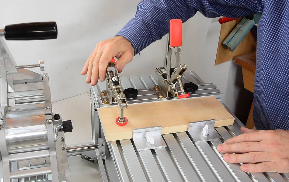
Two (optional) L-shaped pieces of aluminium and knobs can be used as another side stop. When cutting tenons fast, there may be considerable side-forces that can cause the stock to slip to the side, even if it's clamped down with the Bessey clamps.
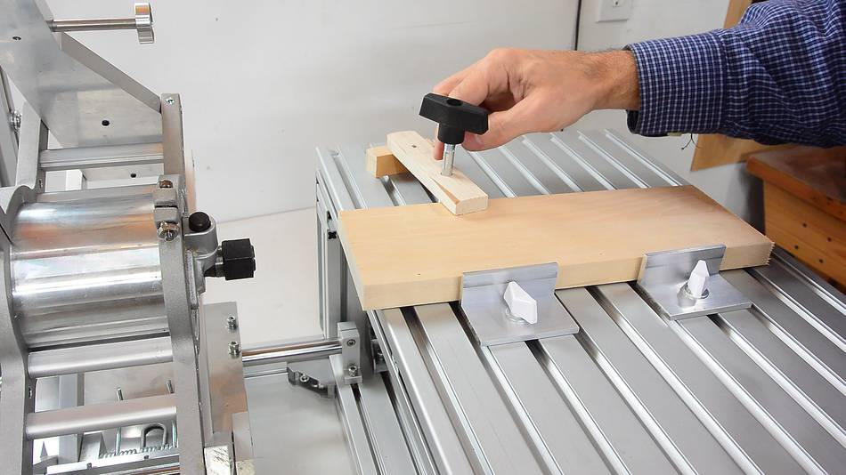
 You can also make your own hold-down clamps. A 5/16" or M8 carriage bolt,
with two sides ground flat, works best in the slots.
You can also make your own hold-down clamps. A 5/16" or M8 carriage bolt,
with two sides ground flat, works best in the slots.
 Or you can buy one of those clamps that fit in a T-slot from Bessey or from Festool.
The clamping force from these clamps is quite good.
Or you can buy one of those clamps that fit in a T-slot from Bessey or from Festool.
The clamping force from these clamps is quite good.
You can buy a pantorouter (current version) at
pantorouter.com
 Assembling the 2018 version
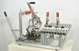 More about buying a pantorouter in 2013
 Pantorouter assembly live stream
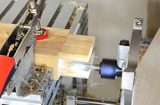 Double tenon with the metal pantorouter
 Kuldeep's pantorouter production
 Making a holdown clamp for the pantorouter
 Making workbench drawers
 More about the wooden pantorouter
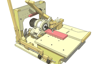 Buy plans for the wooden pantorouter