
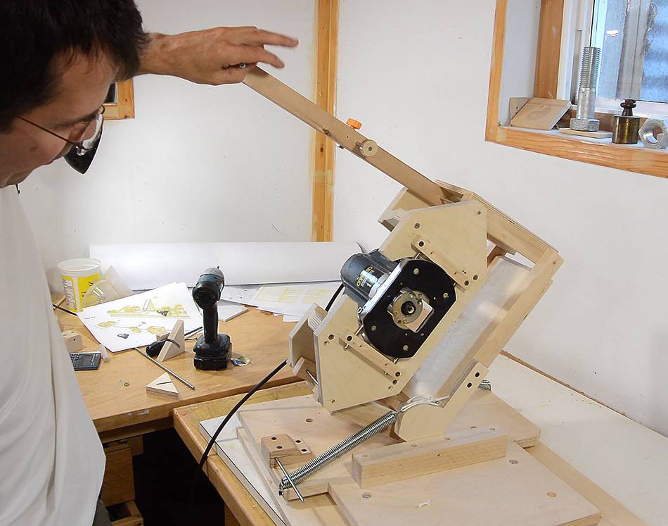
Having built the pantograph,
plunge sled with
drawer glides, table, and template holder,
the pantorouter XL is basically operational, but it's not very convenient to use.
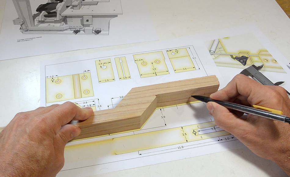
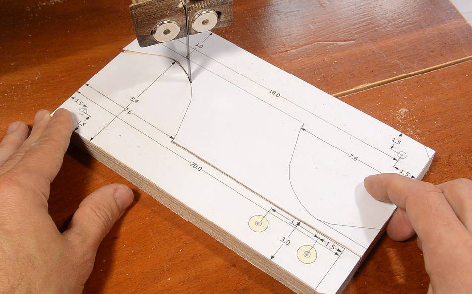
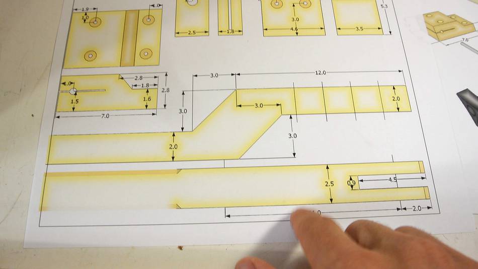 The shape of the lever is simple enough that I can transfer the
measurements onto a piece of wood rather than paste the template on.
The shape of the lever is simple enough that I can transfer the
measurements onto a piece of wood rather than paste the template on.
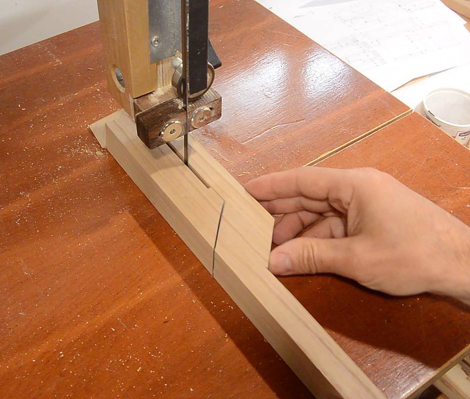
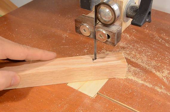
 I made the cuts parallel with the wood on the table saw, then cut
the rest on the bandsaw.
I made the cuts parallel with the wood on the table saw, then cut
the rest on the bandsaw.
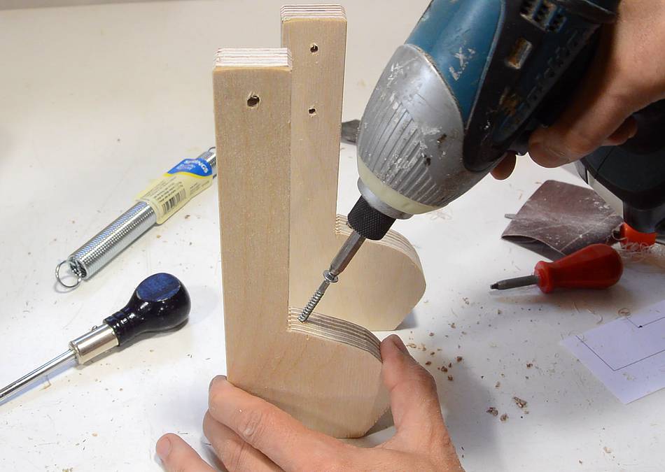
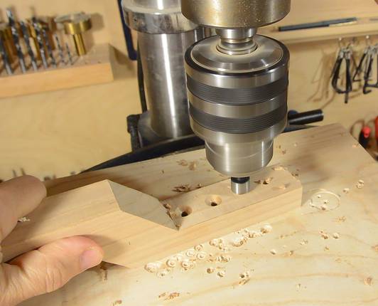 A series of holes needs to be drilled in the end of the lever, to allow
me to mount it slightly further out if I want to later.
A series of holes needs to be drilled in the end of the lever, to allow
me to mount it slightly further out if I want to later.
I just mark the holes off the 1:1 drawing, then drill and countersink them on the drill press.
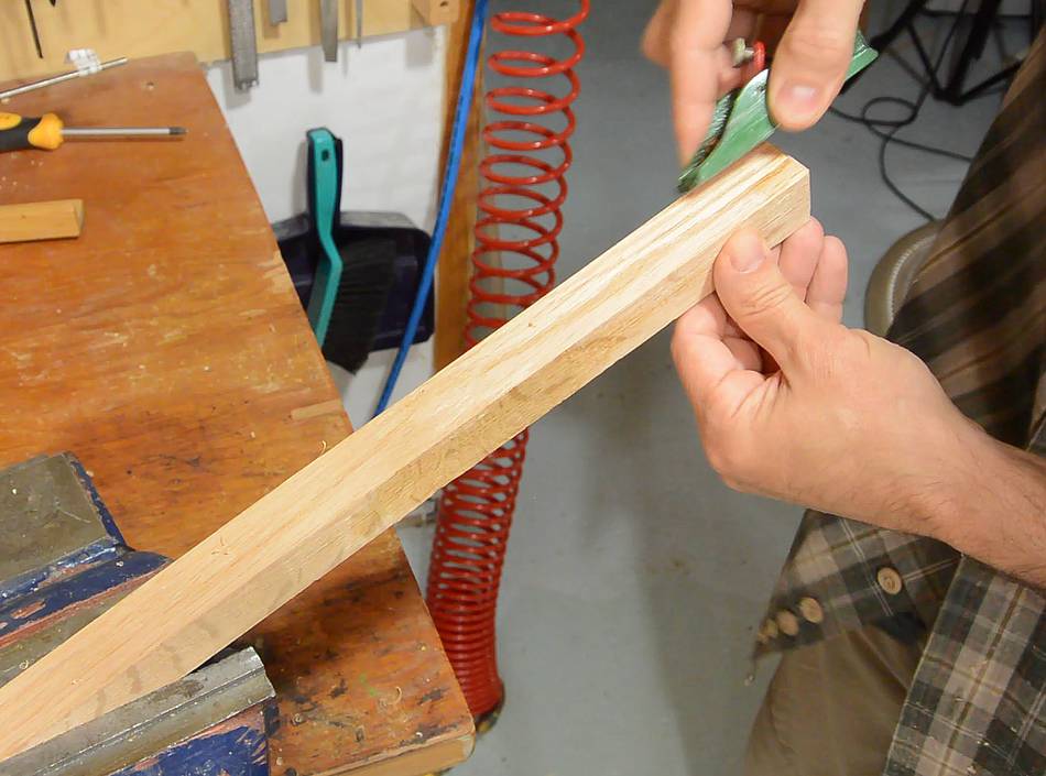
 Next the operating handle. I round the edges of the handle part of the
lever. The other end needs to have a notch cut out of it to couple with
the link I just built.
Next the operating handle. I round the edges of the handle part of the
lever. The other end needs to have a notch cut out of it to couple with
the link I just built.

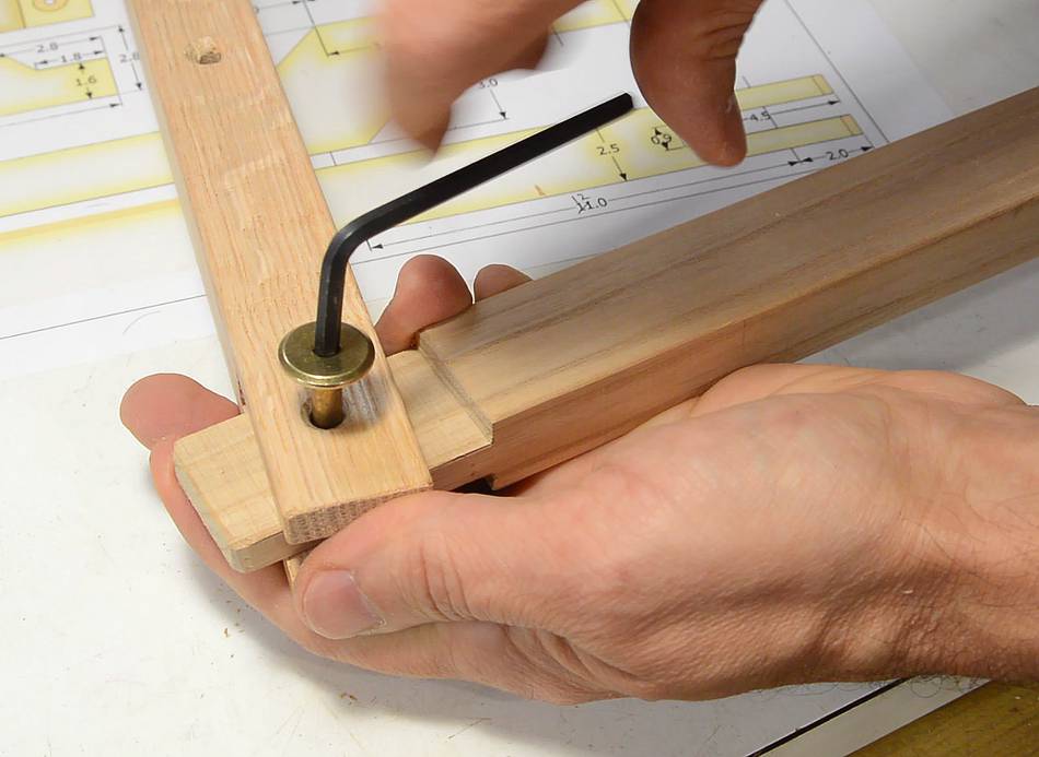
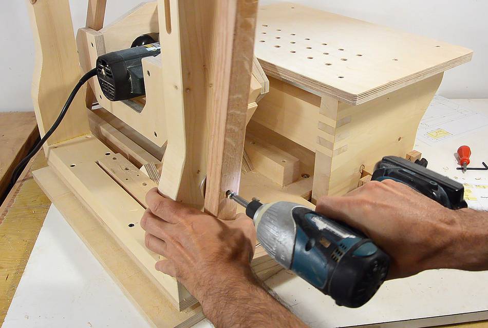
 The operating lever couples to the link as shown. For the lever's main pivot,
I'm using a #10 wood screw, which screws into the template holder.
The operating lever couples to the link as shown. For the lever's main pivot,
I'm using a #10 wood screw, which screws into the template holder.
The hinge with the link could be a piece of steel rod or a wood screw. I'm using part of a knock-down fastener screw. I like the large head on it, and the smooth shank will make a nice pivot.
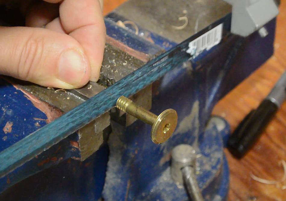
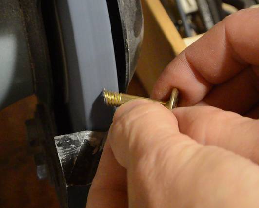 I cut the screw to length, then chamfer the ends to make it easier to
screw into a slightly undersized hole.
I cut the screw to length, then chamfer the ends to make it easier to
screw into a slightly undersized hole.
 The screw threads end up engaging only the other side of the operating lever,
allowing the link in the middle to pivot freely around the smooth part
of the screw's shank.
The screw threads end up engaging only the other side of the operating lever,
allowing the link in the middle to pivot freely around the smooth part
of the screw's shank.
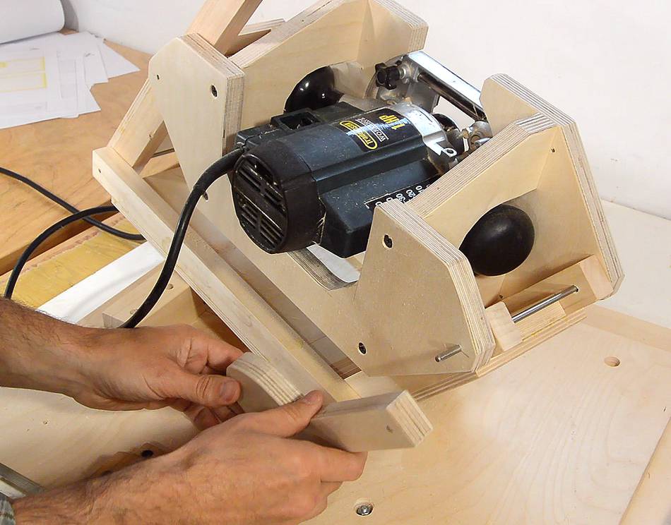
 The lever and link mount on the pantorouter right here, but I will leave
them off for now so I can work on the plunge depth stops.
The lever and link mount on the pantorouter right here, but I will leave
them off for now so I can work on the plunge depth stops.
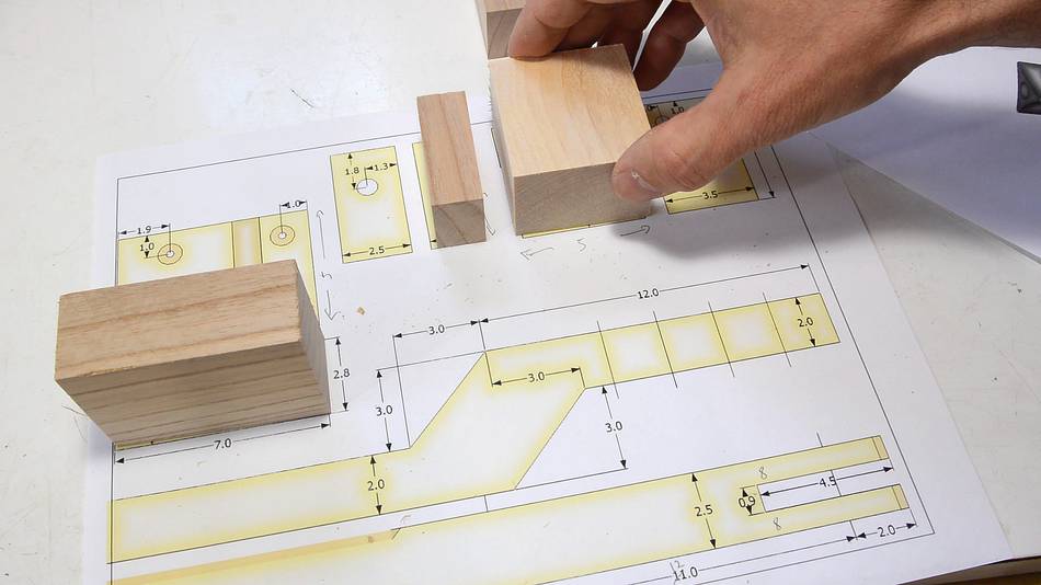 The depth stop mechanism is made from four blocks of wood.
I cut the basic rectangular shape of these on the table saw, and here
I'm checking the size against the 1:1 drawings.
The depth stop mechanism is made from four blocks of wood.
I cut the basic rectangular shape of these on the table saw, and here
I'm checking the size against the 1:1 drawings.
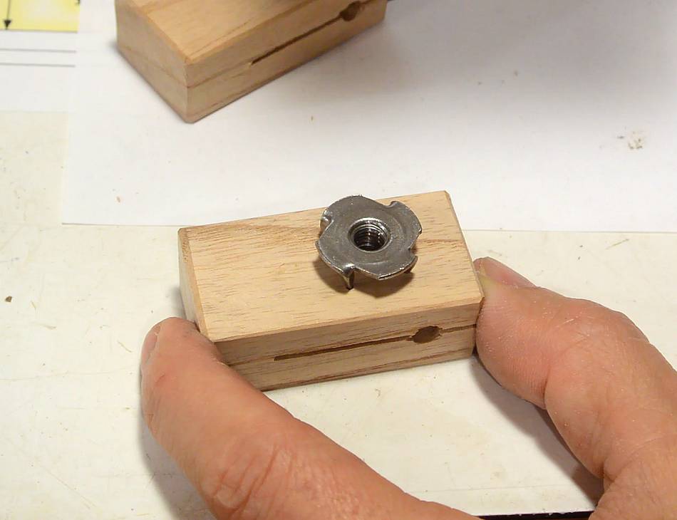
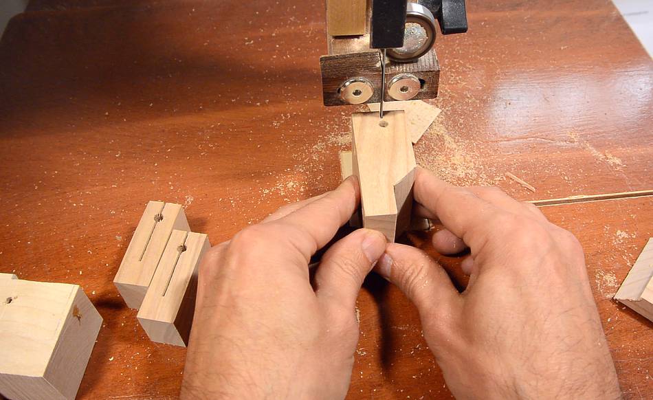 Three of the blocks get a hole the same size as the shaft, but the
largest gets a hole slightly larger so that the shaft will slide freely
in the hole.
Three of the blocks get a hole the same size as the shaft, but the
largest gets a hole slightly larger so that the shaft will slide freely
in the hole.
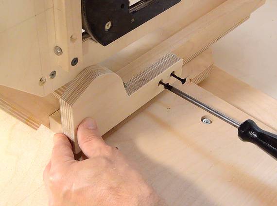
The holes get a slot cut into them to allow the block to clamp down on the shaft. Also, a few other bits are cut off to shape the blocks
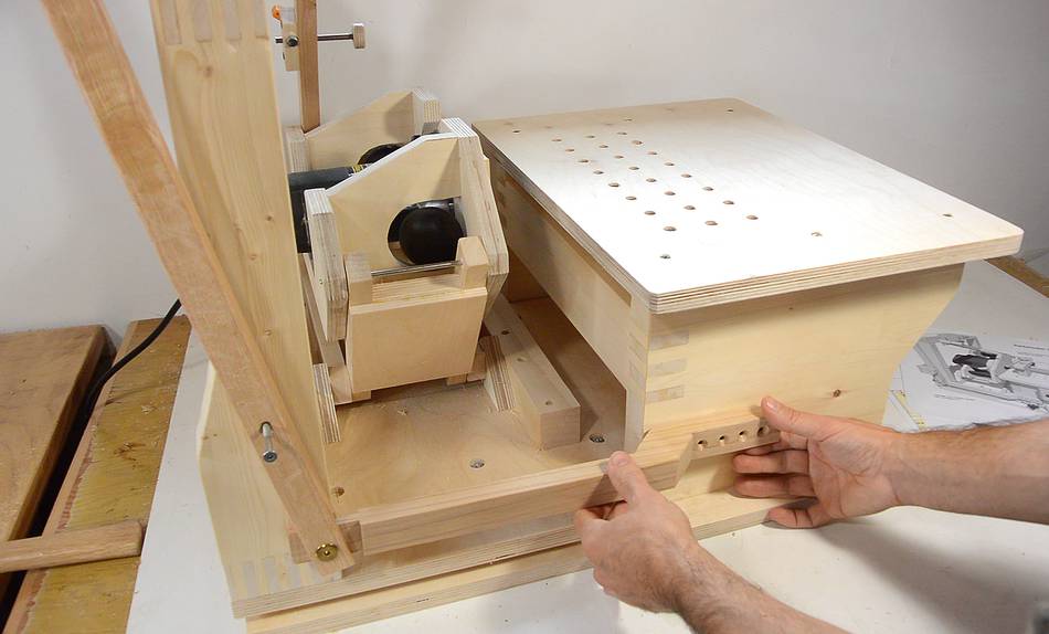
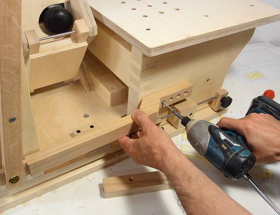
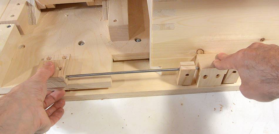 This is how the plunge stops fit on the pantorouter. The block at left
secures the shaft to the sled. The large block at right is screwed to the
table, and the two small blocks clamp onto the shaft to provide depth stops.
This is how the plunge stops fit on the pantorouter. The block at left
secures the shaft to the sled. The large block at right is screwed to the
table, and the two small blocks clamp onto the shaft to provide depth stops.
 In the plans, I have a 1/4" (M6) carriage bolt and threaded knob to clamp
the blocks onto the shaft, similar to the one shown at left.
In the plans, I have a 1/4" (M6) carriage bolt and threaded knob to clamp
the blocks onto the shaft, similar to the one shown at left.
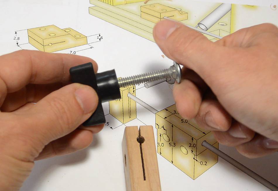
 But I have these screw knobs that I have been
meaning to use for something. They are a bit too short to use with a nut
on the other side, but a T-nut extends them enough to be just right.
But I have these screw knobs that I have been
meaning to use for something. They are a bit too short to use with a nut
on the other side, but a T-nut extends them enough to be just right.
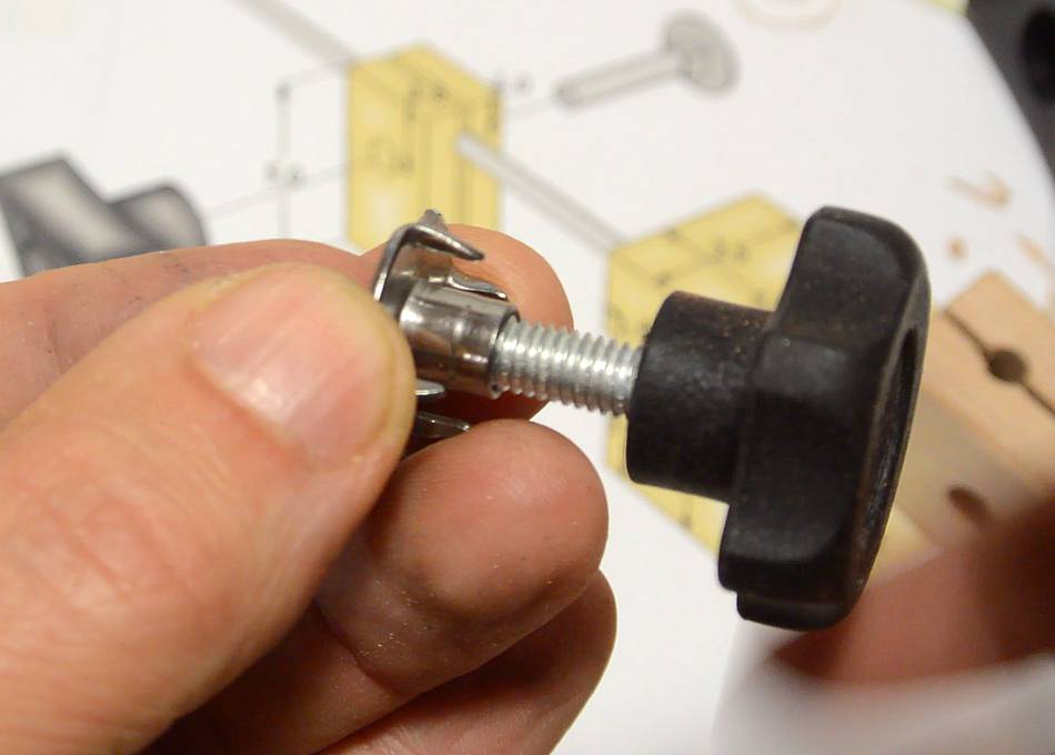
Unfortunately, the knobs have an M6 thread, and the closest I have is 1/4" T-nuts. The T-nut almost fits. So I ran an M6 thread tap into the T-nuts, and now the metric threaded knob screws in just fine.
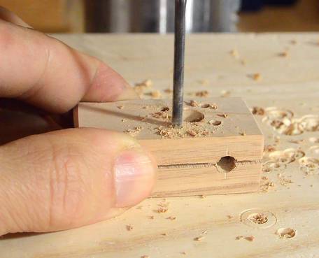 I place the T-nut over the hole, then tap it with a hammer to mark
where the prongs end up, then drill holes for the prongs, large
enough for the prongs to loosely fit into.
I place the T-nut over the hole, then tap it with a hammer to mark
where the prongs end up, then drill holes for the prongs, large
enough for the prongs to loosely fit into.
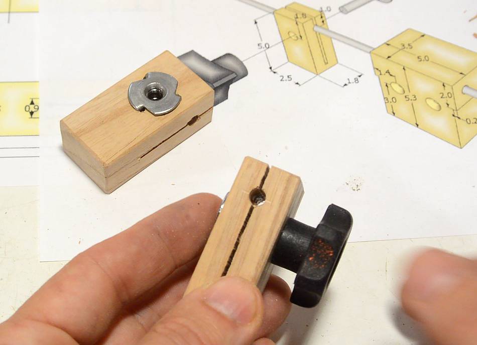 T-nut and knob mounted on the block.
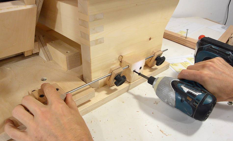 The block that holds the shaft is screwed to the plunge
sled, and the other block to the table. The hole in this
block is larger so that the shaft can slide freely.
The block that holds the shaft is screwed to the plunge
sled, and the other block to the table. The hole in this
block is larger so that the shaft can slide freely.
The small blocks are then clamped to the shaft to serve as stops.
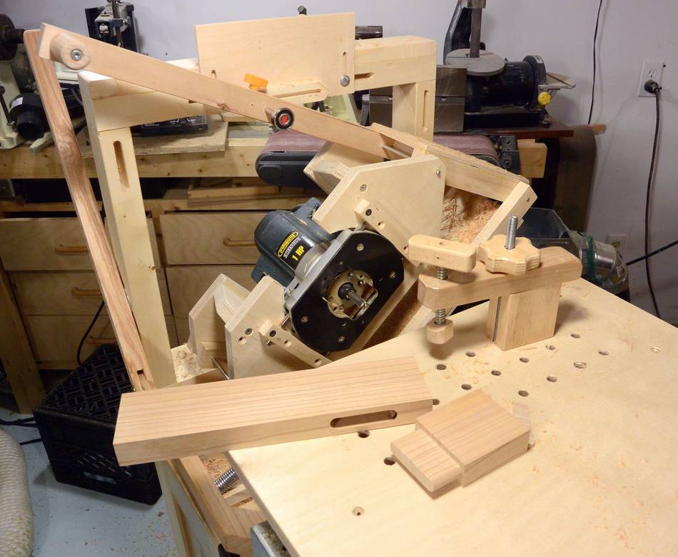
 And the plunge lever can now be mounted right above the depth stops.
 Gravity always pulls the router down. Though the operating lever
provides a 2:1 advantage, lifting up the router by the operating lever
is still tiring over time. To help lift the router up, I'll be adding
springs that push the two pantograph links up, which in turn lifts up
the router.
Gravity always pulls the router down. Though the operating lever
provides a 2:1 advantage, lifting up the router by the operating lever
is still tiring over time. To help lift the router up, I'll be adding
springs that push the two pantograph links up, which in turn lifts up
the router.
 Two cam-shapes for a string to wrap around are cut from Baltic birch,
using 1:1 templates, on the bandsaw.
Two cam-shapes for a string to wrap around are cut from Baltic birch,
using 1:1 templates, on the bandsaw.
 A screw on the inside corner of these will allow a loop of string to hook
onto them.
A screw on the inside corner of these will allow a loop of string to hook
onto them.
 One of these spring cams mounts to the front. It goes on the main shaft
and also screws onto the long link.
One of these spring cams mounts to the front. It goes on the main shaft
and also screws onto the long link.
The other cam just slides onto the shafts of the pantograph. The holes in the cams are slightly arger than the shafts to let them slide on easily.
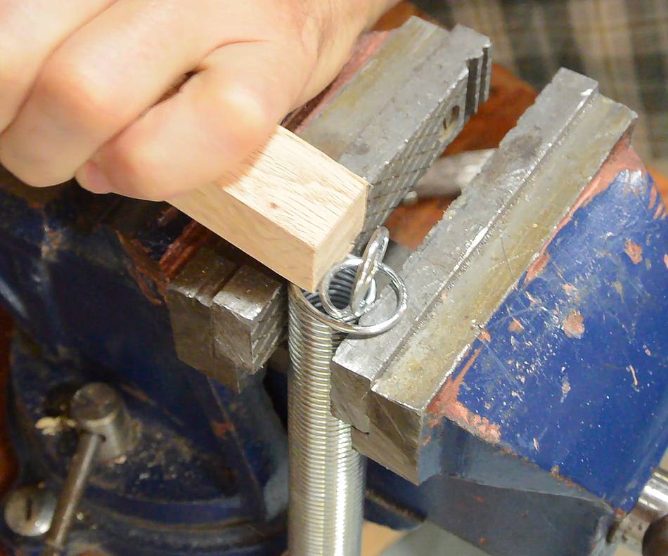
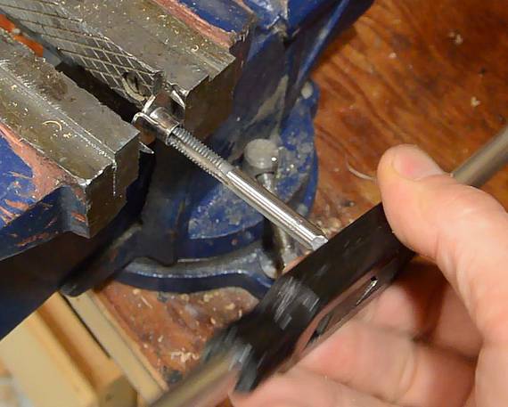
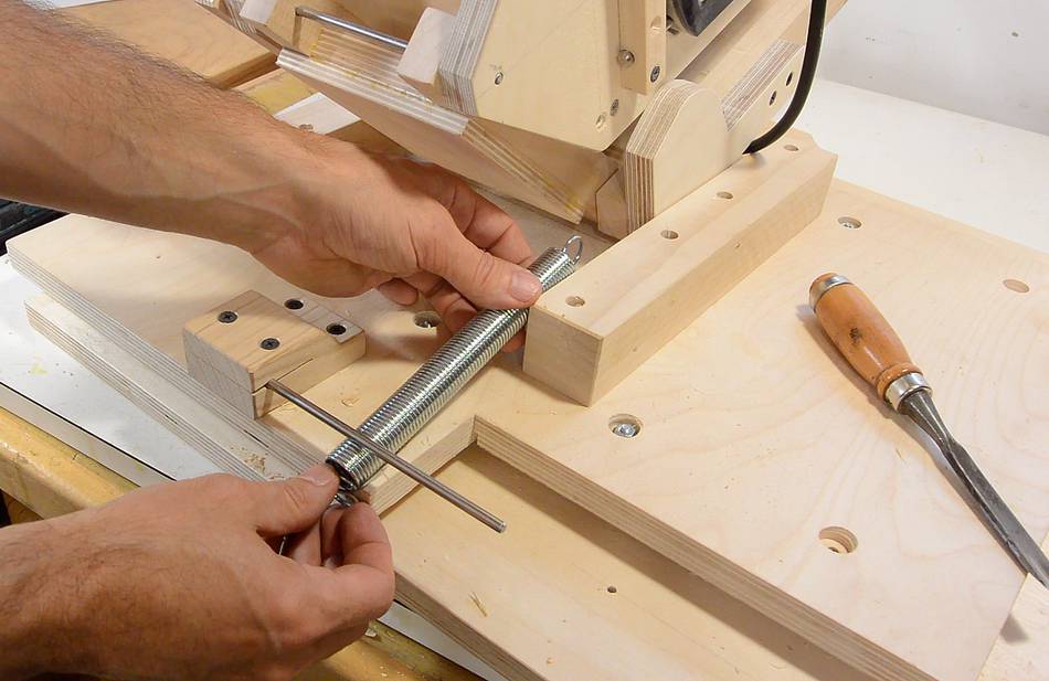
 The springs I bought at Lowes are slightly too long, so instead of using the loops
at the end, I'm bending the last loop to the side on the vise, using a piece of wood
and a hammer, then cutting off the original end loop.
The springs I bought at Lowes are slightly too long, so instead of using the loops
at the end, I'm bending the last loop to the side on the vise, using a piece of wood
and a hammer, then cutting off the original end loop.
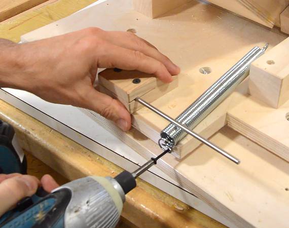
 The sideways-bent loop screws to the edge of the plywood.
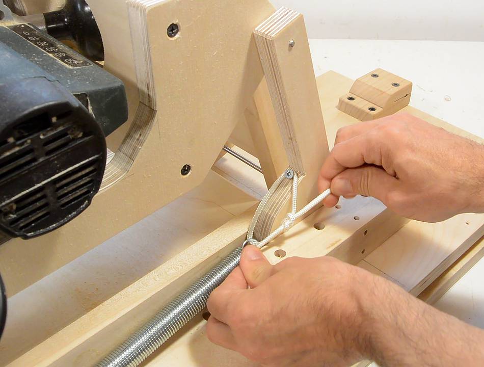 And some string (sash cord) ties the spring to the screw on the cam.
 With the link pivoted all the way to the other side, the spring
has quite a bit of stretch to it. Imagine the long link held in a
fixed position, this spring will effectively pull the short link to
lift up the router.
With the link pivoted all the way to the other side, the spring
has quite a bit of stretch to it. Imagine the long link held in a
fixed position, this spring will effectively pull the short link to
lift up the router.
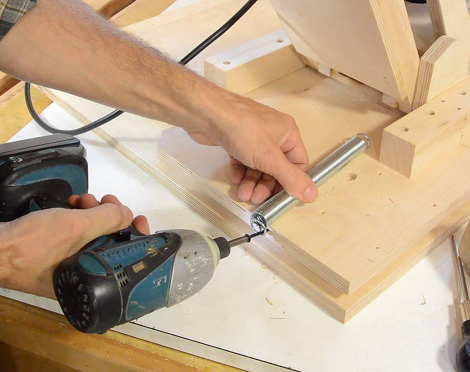
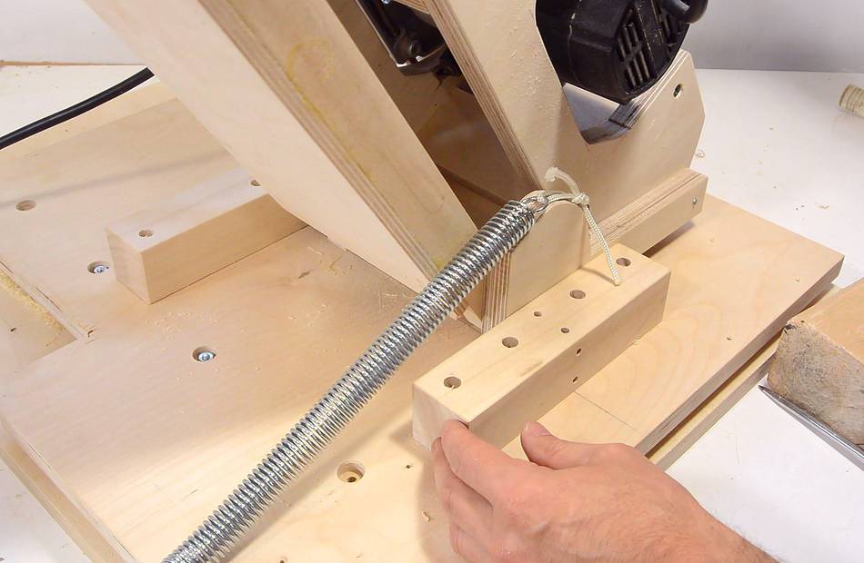
 The other spring cam is on the front. The spring needs to go under the shaft
for the plunge depth stops. I hadn't drawn how the spring attaches on that
end yet, and the spring is long enough that it needs to go under this shaft.
The other spring cam is on the front. The spring needs to go under the shaft
for the plunge depth stops. I hadn't drawn how the spring attaches on that
end yet, and the spring is long enough that it needs to go under this shaft.
I had to carve out a notch to make room for it. I moved the shaft for the depth stops a bit higher in the plans, so you shouldn't need to carve a notch to make room for the spring.
 The springs aren't strong enough to counteract the full weight of the router.
Even though it's a smaller router, it probably isn't any lighter than
the motor-only unit of a full-sized interchangeable base router
that I used on my other machine.
The springs aren't strong enough to counteract the full weight of the router.
Even though it's a smaller router, it probably isn't any lighter than
the motor-only unit of a full-sized interchangeable base router
that I used on my other machine.
 And another minor touch, a piece of dowel as an operator handle.
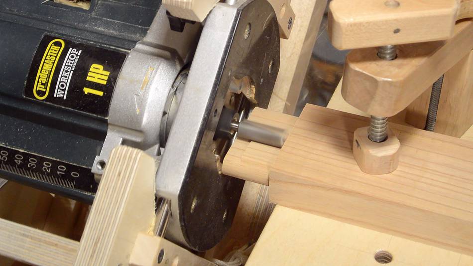 Ready for some more testing. Here cutting a tenon. A sizable tenon for
such a small router, but I can take it in steps.
Ready for some more testing. Here cutting a tenon. A sizable tenon for
such a small router, but I can take it in steps.
 And the corresponding mortise cut. Makes a nice pop when the tenon is pulled
out of the mortise quickly.
And the corresponding mortise cut. Makes a nice pop when the tenon is pulled
out of the mortise quickly.
Next: Adjusting for accuracy