 I first came up with the quick-set
tenon jig in 2008. But I didn't
make a video of building it, so I figured it was time to
revisit this project and document it in more detail.
I first came up with the quick-set
tenon jig in 2008. But I didn't
make a video of building it, so I figured it was time to
revisit this project and document it in more detail.
I first came up with the quick-set
tenon jig in 2008. But I didn't
make a video of building it, so I figured it was time to
revisit this project and document it in more detail.
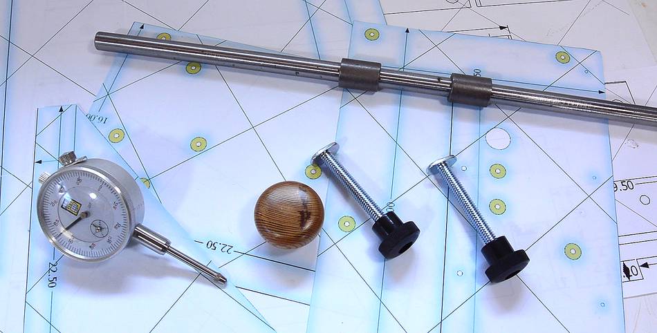 The jig relies on a few bits of not quite common hardware. The 1/2"
(or 12 mm) steel rod and bronze bushings are the most unusual.
You can buy that sort of thing online (from McMaster if you are in the
US), or find a local bearing store in the phone book (most major cities
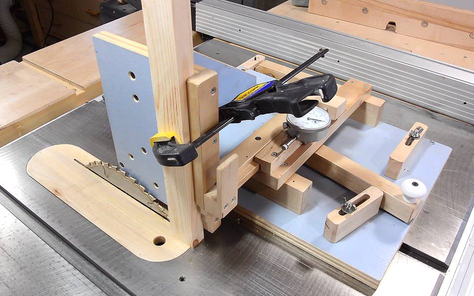
have a bearing store). I also have a dial indicator with 1" (25 mm)
travel, though a caliper could also be used. Also, a knob for the
lever. Not shown, the 3/16" (5 mm) steel rod. You could also use
smooth nails of similar thickness for the steel pins.
You could also use a metal
bar for the table saw slot, though hardwood will do fine.
The jig relies on a few bits of not quite common hardware. The 1/2"
(or 12 mm) steel rod and bronze bushings are the most unusual.
You can buy that sort of thing online (from McMaster if you are in the
US), or find a local bearing store in the phone book (most major cities
have a bearing store). I also have a dial indicator with 1" (25 mm)
travel, though a caliper could also be used. Also, a knob for the
lever. Not shown, the 3/16" (5 mm) steel rod. You could also use
smooth nails of similar thickness for the steel pins.
You could also use a metal
bar for the table saw slot, though hardwood will do fine.
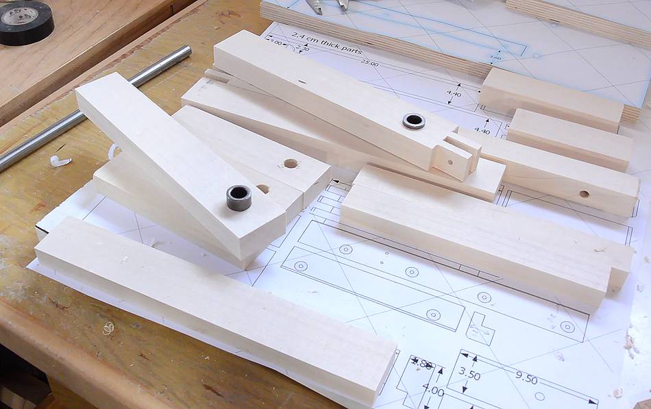
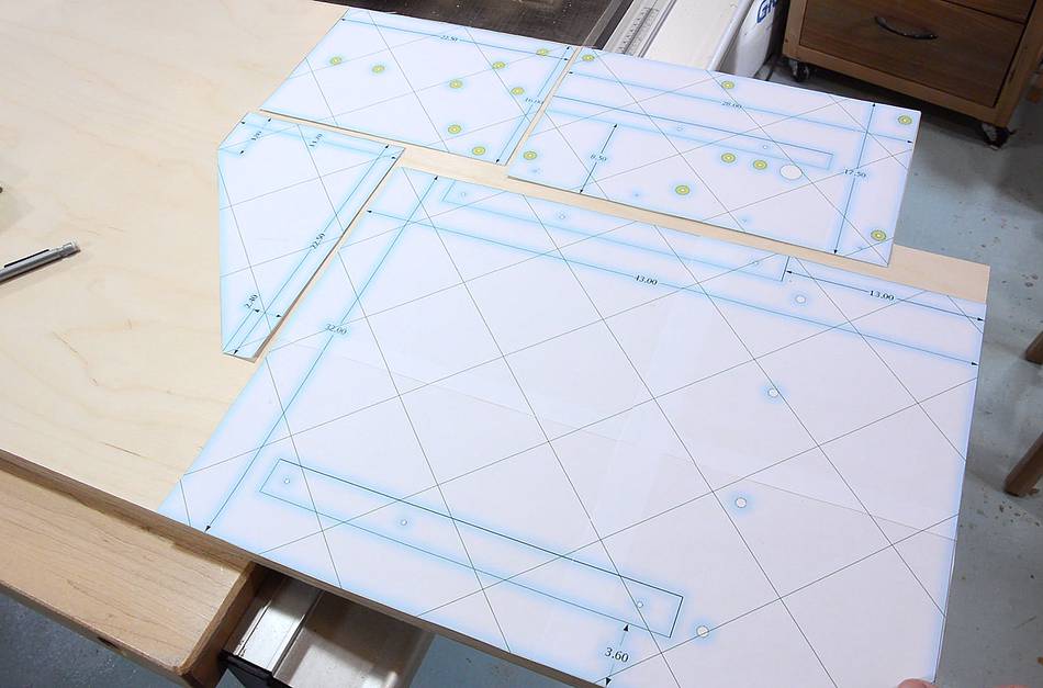 I printed out all the 1:1 templates and laid these out on some 18 mm
birch plywood to make the best use of the piece that I have. Regular
plywood (of good quality) 18 or 19 mm (or 3/4") thick can also be used.
Birch plywood is not cheap, but I'm only using less than $10 of it
here. Worth it to me.
I printed out all the 1:1 templates and laid these out on some 18 mm
birch plywood to make the best use of the piece that I have. Regular
plywood (of good quality) 18 or 19 mm (or 3/4") thick can also be used.
Birch plywood is not cheap, but I'm only using less than $10 of it
here. Worth it to me.
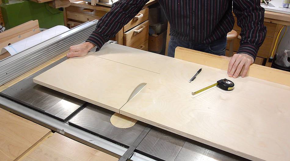
 I have gotten into the habit of cutting corners out of whole sheets so
all the scraps remain in one piece. This makes cutting
it tricky sometimes, but better use of the wood overall.
I have gotten into the habit of cutting corners out of whole sheets so
all the scraps remain in one piece. This makes cutting
it tricky sometimes, but better use of the wood overall.
 Plywood pieces all cut, with the templates lying on top.
I didn't glue them on.
Plywood pieces all cut, with the templates lying on top.
I didn't glue them on.

 Next cutting up the hardwood. I'm using some maple, but any hardwood
will do. I'd recommend anything with a closed grain. I don't
recommend oak, ash or hickory because the prominent growth rings can
cause drills to wander.
Next cutting up the hardwood. I'm using some maple, but any hardwood
will do. I'd recommend anything with a closed grain. I don't
recommend oak, ash or hickory because the prominent growth rings can
cause drills to wander.
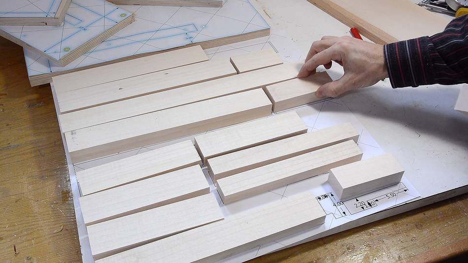 Hardwood pieces all cut. I'm placing these all on top of my 1:1
printout to keep track.
Hardwood pieces all cut. I'm placing these all on top of my 1:1
printout to keep track.
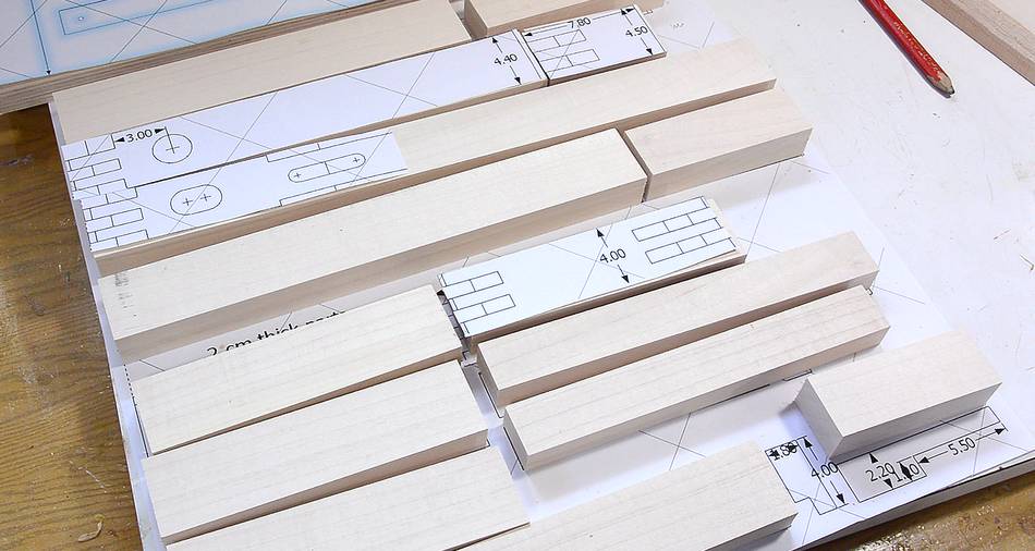
 I printed a second copy of the templates, which I cut up to use as
cutting templates for the more complicated parts. I figured it
would be wasteful for others to print two whole copies, so
I added a separate page to the plans
with just the complicated shapes to use as cutting templates.
I printed a second copy of the templates, which I cut up to use as
cutting templates for the more complicated parts. I figured it
would be wasteful for others to print two whole copies, so
I added a separate page to the plans
with just the complicated shapes to use as cutting templates.
The fingered ends form hinges with steel pins, so they need to be cut carefully. But before cutting these out, I drill the holes for the hinge pins.

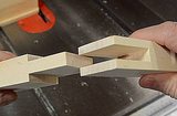
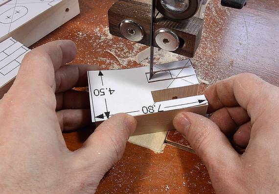 Cutting the fingers on the bandsaw. Something like a tenon jig would
allow you to cut these cleaner, but the bandsaw is easier, and these
fingers don't need to be that precise. It is important to cut not just
to the line, but to cut the line itself away too to make sure the
pieces will fit together.
Cutting the fingers on the bandsaw. Something like a tenon jig would
allow you to cut these cleaner, but the bandsaw is easier, and these
fingers don't need to be that precise. It is important to cut not just
to the line, but to cut the line itself away too to make sure the
pieces will fit together.
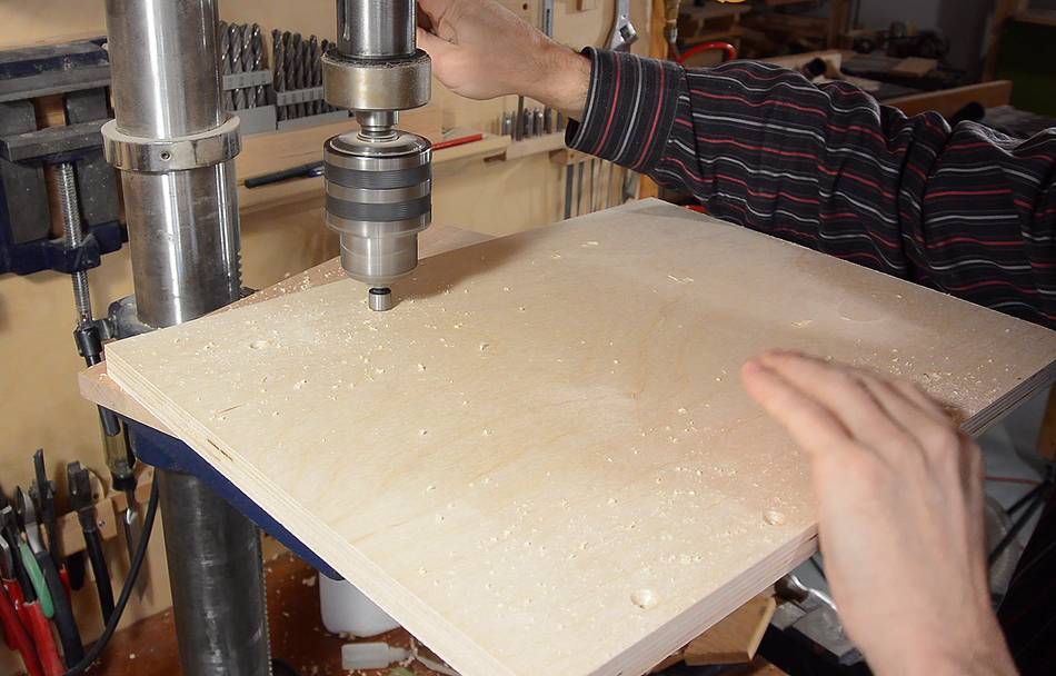
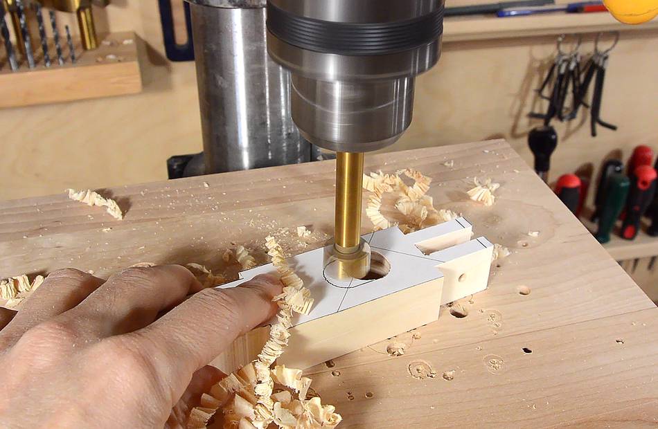 Drilling a clearance hole for where the main lever needs to fit around a shaft.
Two overlapping holes with a 3/4" Forstner bit do the job.
Drilling a clearance hole for where the main lever needs to fit around a shaft.
Two overlapping holes with a 3/4" Forstner bit do the job.

 Another slot in the lever where it fits around the fulcrum.
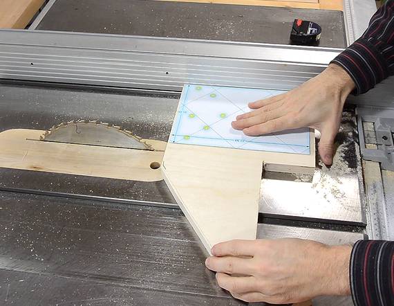
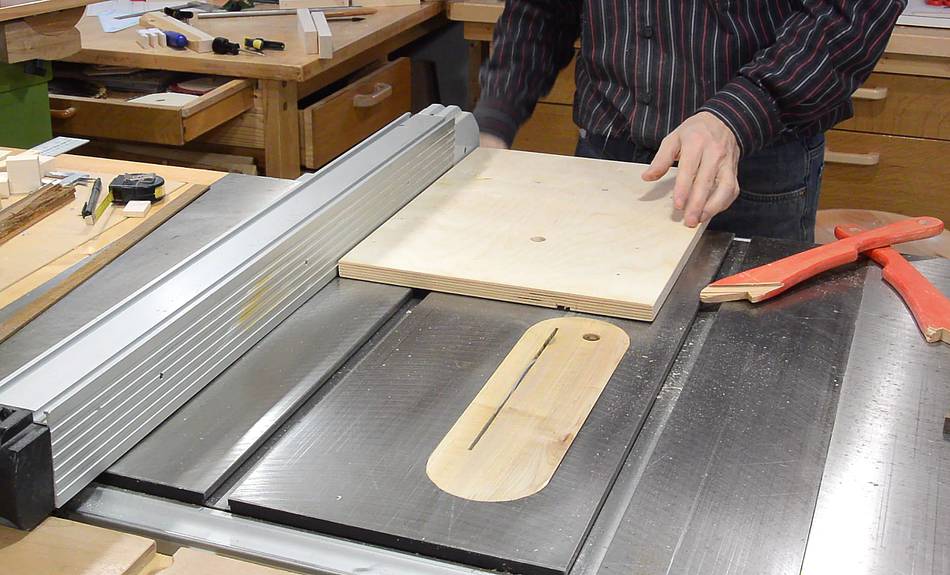
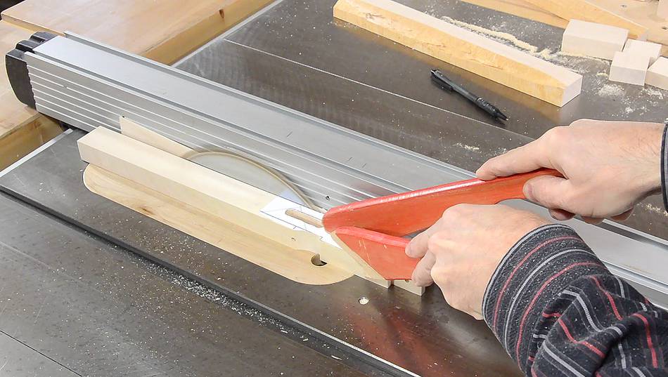 Now cutting the long part of the main lever to width. These cuts are made
part-way through, not to the end. You can see the completed shape in the
back of the next photo. The bandsaw would have been easier, but the
table saw makes a cleaner cut.
Now cutting the long part of the main lever to width. These cuts are made
part-way through, not to the end. You can see the completed shape in the
back of the next photo. The bandsaw would have been easier, but the
table saw makes a cleaner cut.
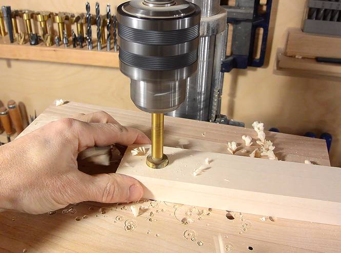
 Drilling the holes out. I tried several different 1/2" drill bits to
find one that produced holes that were just snug.
Drilling the holes out. I tried several different 1/2" drill bits to
find one that produced holes that were just snug.
 I needed to drill holes for the bushings that slide on the shafts.
 Last time I had a hard time getting these bushings to line up properly.
Self-aligning bushings might be a better choice here, but I already had
these bushings.
Last time I had a hard time getting these bushings to line up properly.
Self-aligning bushings might be a better choice here, but I already had
these bushings.
 Bushings partway pressed into the pieces.
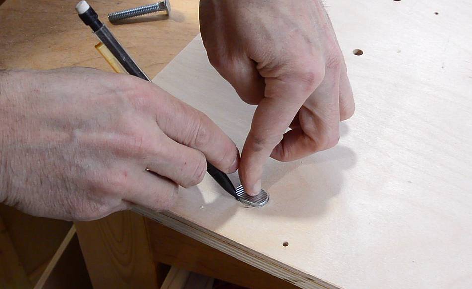
 Preparing the base. I'm using the paper template to locate the holes
I need to drill in the base.
I punch the location of every hole center through the template
using an awl...
Preparing the base. I'm using the paper template to locate the holes
I need to drill in the base.
I punch the location of every hole center through the template
using an awl...
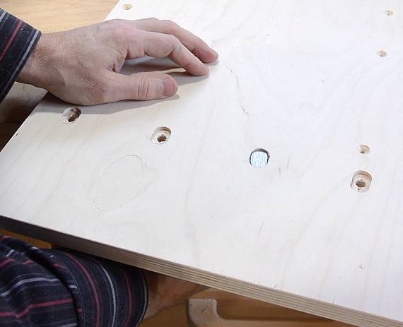
 ... then drill the holes, then countersink. Be sure to flip the
base before countersinking, otherwise you end up with the countersinks
on the top.
... then drill the holes, then countersink. Be sure to flip the
base before countersinking, otherwise you end up with the countersinks
on the top.
This is the sort of thing a CNC machine could do well, but punching the hole centers and drilling them all at once is pretty fast. The job is done in less time than it would take to mount the workpiece in a CNC router.
 In my plans I specify carriage bolts to hold the stops to the base, but
I have some jig bolts with these funny oblong heads, designed to go
into T-tracks. These are harder to find, but even better for this
application. They came as part of a "
149-piece Jig & Fixture Parts Kit"
from Lee Valley tools. (I bought that kit mostly for all the threaded plastic knobs)
In my plans I specify carriage bolts to hold the stops to the base, but
I have some jig bolts with these funny oblong heads, designed to go
into T-tracks. These are harder to find, but even better for this
application. They came as part of a "
149-piece Jig & Fixture Parts Kit"
from Lee Valley tools. (I bought that kit mostly for all the threaded plastic knobs)
Here I'm tracing around the oblong shape of the head.

 Then drilling two overlapping holes with a Forstner bit to carve
out the cavity, plus chiseling out a bit between the holes.
Then drilling two overlapping holes with a Forstner bit to carve
out the cavity, plus chiseling out a bit between the holes.
The nice thing about these jig bolts is that they fit loosely in the hole but the oblong head won't spin in the oblong hole.
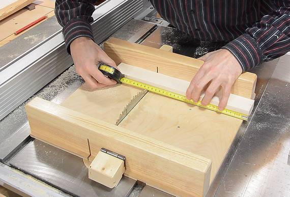
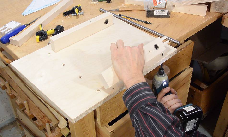
 Before moving on with other stuff, I also cut a slot in the
base for the miter slot guide bar. This is easier to do
without anything mounted to the base.
Before moving on with other stuff, I also cut a slot in the
base for the miter slot guide bar. This is easier to do
without anything mounted to the base.
The slot should be positioned so that the base ends up about 65 mm from the blade,
 With all the cuts and holes made on the base, time to get back to the
pieces with the bushings. Here I'm screwing them on from below.
With all the cuts and holes made on the base, time to get back to the
pieces with the bushings. Here I'm screwing them on from below.
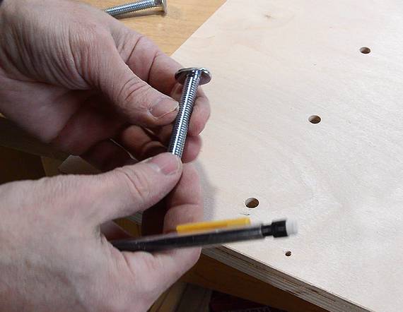
 Inserting the shaft through a bushing to see how it lines up
The shaft ended up about 2 mm too high when hit
it the other bushing, so the alignment needs to be tweaked.
Inserting the shaft through a bushing to see how it lines up
The shaft ended up about 2 mm too high when hit
it the other bushing, so the alignment needs to be tweaked.
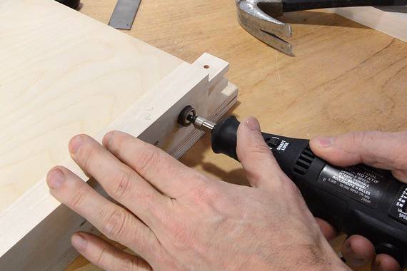
I used a small sanding drum on a Dremel tool to grind away at the hole near the top on the outside edge and near the bottom on the inside edge. I was able to get it to align after that.
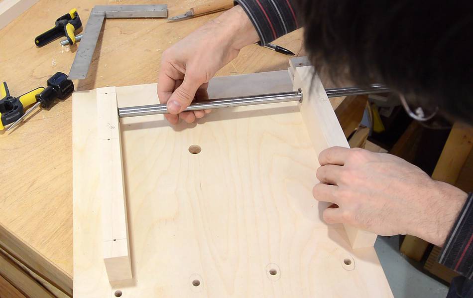
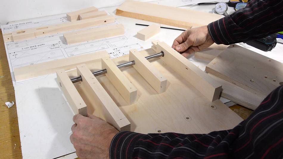 The steel rod goes through three pieces of hardwood that I drilled earlier.
The side-to-side carriage mounts on these.
The steel rod goes through three pieces of hardwood that I drilled earlier.
The side-to-side carriage mounts on these.
On to Part 2 of building the tenon jig
To my woodworking website
 Bridle joint with the
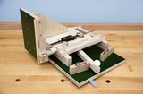 Harlan Opie's quick-set tenon jig
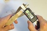 Mortise and tenon joint accuracy
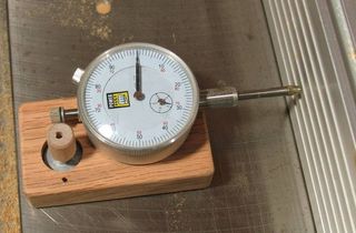 Table saw fence
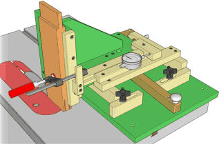 Buy plans for the tenon jig