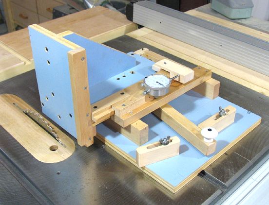
Quick-set tenon jig
This is my second design of a tenon jig. My previous tenon jig was based on this screw mechanism and 5/8" shafts that allowed for a linear slide. The parts were a lucky yard sale find. As such, it was not a design that I could suggest to anybody that they should build, seeing that one can't just find such parts on demand.
I have since revised the design to do even more
The other thing that I wanted to come up with was a jig that could very quickly and accurately be adjusted between two stops, so that when cutting tenons, one could just clamp the work piece, and then cut both sides in rapid succession. This would eliminate not only the time it takes to reclamp for every cut, but also any inaccuracy that reclamping or flipping the work piece introduces.
 Adjustment for the jig is based on a lever mechanism that gives a 4:1 mechanical advantage at
the point of the handle for adjusting the jig.
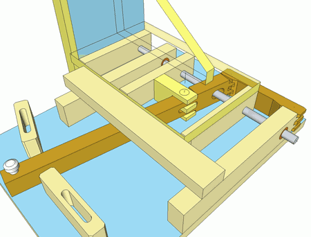
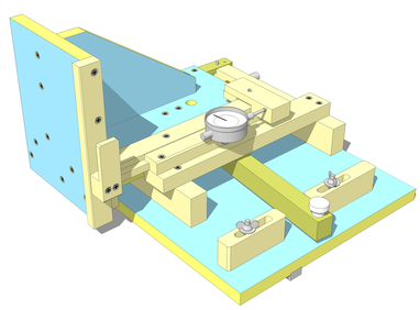
I spent quite a bit of time working out the dimensions, making
sure that the parts would not hit each other and such, so I first drew a 2D model, and then a 3D
CAD model of the jig before I started building it.
Adjustment for the jig is based on a lever mechanism that gives a 4:1 mechanical advantage at
the point of the handle for adjusting the jig.
I spent quite a bit of time working out the dimensions, making
sure that the parts would not hit each other and such, so I first drew a 2D model, and then a 3D
CAD model of the jig before I started building it.
The parts in dark brown at left are the lever mechanism. I displayed the base plate of the carriage transparent, so that the lever and its hinging mechanism could be seen.
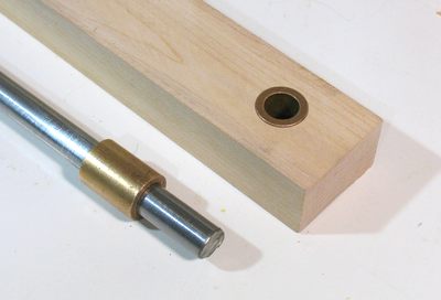 The sliding mechanism is based on a piece of 1/2" drill rod and bronze bushings from the
Metal Supermarket.
Sliding on the drillrod shaft are two bronze bushings, 1" long
and 3/4" outer diameter. Conveniently, the bushings press fit into 3/4" holes drilled
with a forstner bit. The force of my weight is just enough to get the bushing into the hole,
so it's moderately tight without risk of splitting the wood.
The sliding mechanism is based on a piece of 1/2" drill rod and bronze bushings from the
Metal Supermarket.
Sliding on the drillrod shaft are two bronze bushings, 1" long
and 3/4" outer diameter. Conveniently, the bushings press fit into 3/4" holes drilled
with a forstner bit. The force of my weight is just enough to get the bushing into the hole,
so it's moderately tight without risk of splitting the wood.
I ended up giving the drill rod a further polish with extremely fine sand paper - the kind that one can use to hone a knife with. And a few drops of heavy oil on it make it slide easier too, of course.
If you have an old wide carriage dot matrix printer kicking around, those often have a suitable steel rod for the print head to slide on, though often in Metric sizes. Suitable bronze bushings of various sizes can also be bought at any industrial bearing supply store (look in the phone book for bearings)
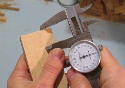 The accuracy of this jig would affect the accuracy of anything that I'd subsequently build with it.
I ended up using calipers to set the table saw, and for marking every critical hole.
A clever trick I like
to use is to just use the caliper as a marking gauge. I use the sharp jaws to scratch a line
directly into the wood, with the other jaw of the caliper referenced against the edge of the wood.
The accuracy of this jig would affect the accuracy of anything that I'd subsequently build with it.
I ended up using calipers to set the table saw, and for marking every critical hole.
A clever trick I like
to use is to just use the caliper as a marking gauge. I use the sharp jaws to scratch a line
directly into the wood, with the other jaw of the caliper referenced against the edge of the wood.
 Despite my best efforts in accuracy, one thing that gave me problem is getting the two bushings
precisely aligned. I could get them in the right position, but the drill would drift to the side
ever so slightly (by maybe a tenth of a millimeter) as it went through the wood. With the bushings
in the right place, but not pointing at each other quite exactly enough, there was lots of friction
on the shaft slid between them. I re-made the one part several times, but eventually just resorted
to scraping out parts of the hole to allow the bushing to face just right.
Despite my best efforts in accuracy, one thing that gave me problem is getting the two bushings
precisely aligned. I could get them in the right position, but the drill would drift to the side
ever so slightly (by maybe a tenth of a millimeter) as it went through the wood. With the bushings
in the right place, but not pointing at each other quite exactly enough, there was lots of friction
on the shaft slid between them. I re-made the one part several times, but eventually just resorted
to scraping out parts of the hole to allow the bushing to face just right.
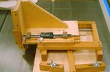
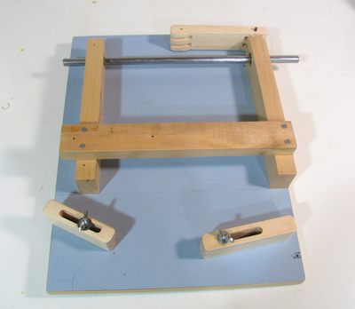 This photo shows the base of the tenon jig. The shaft is actually part of the carriage, but I slid it into
the base just to illustrate how it goes together.
This photo shows the base of the tenon jig. The shaft is actually part of the carriage, but I slid it into
the base just to illustrate how it goes together.
The blocks on the front are just held in with wing nuts with carriage bolts stuck through the base from the bottom
The material is reclaimed plywood, which happened to have a coat of blue-ish gray paint on it. Unpainted would perhaps have been better, but the paint was well applied and thin, and I actually like how the jig ended up looking with the painted plywood!
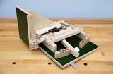
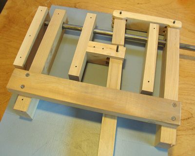 This photo shows the base, plus the pieces that are normally screwed to the bottom of the carriage.
The three short pieces have 1/2" holes in them that the shaft sticks in with some friction.
It's enough friction to keep it securely held in place, but not too much - I can still pull the
shaft out.
This photo shows the base, plus the pieces that are normally screwed to the bottom of the carriage.
The three short pieces have 1/2" holes in them that the shaft sticks in with some friction.
It's enough friction to keep it securely held in place, but not too much - I can still pull the
shaft out.
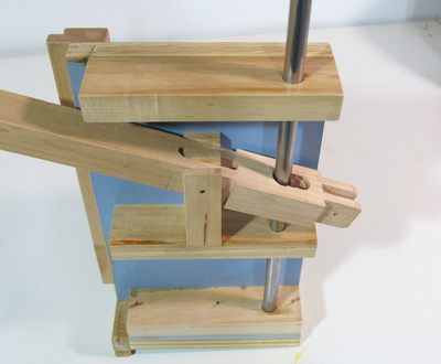 This photo shows the carriage bottom, with the shaft inserted. You can see the slot in the
tilted lever, which allows it to move around the shaft.
This photo shows the carriage bottom, with the shaft inserted. You can see the slot in the
tilted lever, which allows it to move around the shaft.
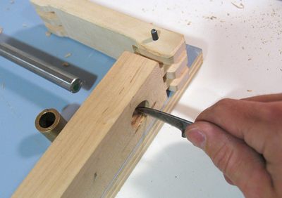
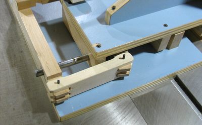 The lever ties to the base of the tenon jig using this link. The link is hinged on 3/16" pins.
I used 3/16" steel rod, which fit exactly and tightly into 3/16" holes. If I didn't have
a 3/16" steel shaft handy, I would probably have tried various combinations of nails and
drills to get a similarly tight fit. 3/16" steel shaft can also be bought at stores like
the Home Depot.
The lever ties to the base of the tenon jig using this link. The link is hinged on 3/16" pins.
I used 3/16" steel rod, which fit exactly and tightly into 3/16" holes. If I didn't have
a 3/16" steel shaft handy, I would probably have tried various combinations of nails and
drills to get a similarly tight fit. 3/16" steel shaft can also be bought at stores like
the Home Depot.
The tight fit of the shaft allowed me to avoid having any play on the linkage, as any play would ultimately add to inaccuracy of cuts made with the jig.
Ironically, I used another tenon jig to cut the slots in the links! Though these don't need to be quite as super accurate to require a tenon jig, so if you don't already have a tenon jig, you could just cut them out with a band saw.
 The carriage is supported on the back side by the steel shaft sliding in the bushings.
On the front side, a wooden rail extends past the carriage and slides on a piece of wood that
is part of the base.
The carriage is supported on the back side by the steel shaft sliding in the bushings.
On the front side, a wooden rail extends past the carriage and slides on a piece of wood that
is part of the base.
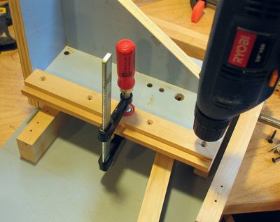
The photo shows drilling the screw holes to mount this rail. To make sure the screw holes would line up, I just clamped the rail to the jig and drilled through both parts at once.
The whole jig is held together by screws only. Glue and screws would be better, but I found myself disassembling the jig and shaving a little bit off of parts here and there to correct for some inaccuracies. So if you build a jig like that and intend to glue it, put it together with just screws until you have had the chance to use it a few times, so you don't end up wishing you could take it apart again.
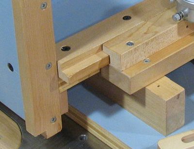 This photo shows how the front of the carriage is guided. It rides
on a horizontal part of the carriage. The front is rabbeted, and another rabbeted piece
of wood holds it down. I made these to have almost no play
in it. Although play on this spot would only affect the depth of the tenons
cut, so its not as critical as other aspects.
This photo shows how the front of the carriage is guided. It rides
on a horizontal part of the carriage. The front is rabbeted, and another rabbeted piece
of wood holds it down. I made these to have almost no play
in it. Although play on this spot would only affect the depth of the tenons
cut, so its not as critical as other aspects.
I also put a few drops of oil on where the parts slide, so that the side to side adjustment would slide a little bit easier.
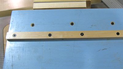 The jig rides in the T slot on a guide rail, which is rabbeted 1.5 mm into the bottom of
the base. I rabbeted it in to help hold it in place tighter, but not so deep as to
cut through too many plys in the plywood base.
The jig rides in the T slot on a guide rail, which is rabbeted 1.5 mm into the bottom of
the base. I rabbeted it in to help hold it in place tighter, but not so deep as to
cut through too many plys in the plywood base.
I was originally going to use a cold rolled steel rail from the Metal Supermarket as a guide rail, but I'm frustrated that these always have a bit of play in the T slot. You can read more about my efforts at making things slide precisely in the t-slot on my table saw sled article and my tenon jig review
This time, I just went with hardwood, which I could cut to a width where it fit the slot exactly. Its only screwed in, so if it wears out, I can replace it.
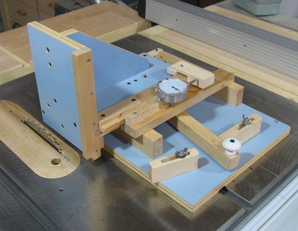
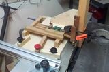
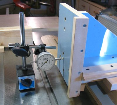 I did lots of checking of the overall accuracy of the jig. This check is to make sure that
the face of the tenon jig is aligned with the blade and T-slots. The reading on the displacement
indicator should not change significantly as the carriage is moved past it.
I did lots of checking of the overall accuracy of the jig. This check is to make sure that
the face of the tenon jig is aligned with the blade and T-slots. The reading on the displacement
indicator should not change significantly as the carriage is moved past it.
 I mounted an extra displacement indicator on the tenon jig, for setting up the cuts.
The displacement indicator itself was easy to mount. I just put a screw through the mounting
hole on the back and screwed it into part of the base.
I mounted an extra displacement indicator on the tenon jig, for setting up the cuts.
The displacement indicator itself was easy to mount. I just put a screw through the mounting
hole on the back and screwed it into part of the base.
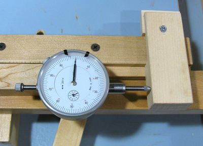
For it to be able to read the position of the carriage, I wanted a movable stop for the dial indicator, seeing that the carriage can move over 2 inches, but the displacement indicator only has a range of 1" that it can display.
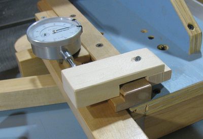 The movable dial indicator reference stop is clamped to the carriage by tightening a
screw in it that is at an angle. This pulls the little block on the end of it closer,
and tightens the movable stop around the piece it is on.
The movable dial indicator reference stop is clamped to the carriage by tightening a
screw in it that is at an angle. This pulls the little block on the end of it closer,
and tightens the movable stop around the piece it is on.
This isn't overly strong, but strong enough to stay consistent for the dial indicator.
I was amazed to find that the jig repeats its positions within a fraction of .001", as long as one is consistent with how fast one moves from one stop to the other stop with the lever. Although if I approach the stops very slowly, versus slamming against them hard, I can get a difference of as much as 0.002"
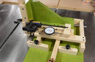
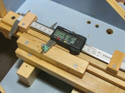 If you don't have a spare dial displacement indicator kicking around, you might consider mounting
a caliper to the jig instead. A caliper has the advantage that it has a larger range
of movement.
I attached the caliper to the carriage part, and the jaw
of the caliper is fixed to a screw on the fixed part with rubber bands. The reference
point for the caliper is the metal of the screws, and the rubber bands only serve to provide
tension to keep the jaw against the screw. I wouldn't recommend a conventional vernier
calipers, because they can't be "zeroed", and they are harder to read when mounted like that.
A digital caliper works out really well, because I always end up using a calculator to figure
out where the positions need to be, and the digital caliper can conveniently be zeroed with
the jigs's face just touching the blade as a reference.
If you don't have a spare dial displacement indicator kicking around, you might consider mounting
a caliper to the jig instead. A caliper has the advantage that it has a larger range
of movement.
I attached the caliper to the carriage part, and the jaw
of the caliper is fixed to a screw on the fixed part with rubber bands. The reference
point for the caliper is the metal of the screws, and the rubber bands only serve to provide
tension to keep the jaw against the screw. I wouldn't recommend a conventional vernier
calipers, because they can't be "zeroed", and they are harder to read when mounted like that.
A digital caliper works out really well, because I always end up using a calculator to figure
out where the positions need to be, and the digital caliper can conveniently be zeroed with
the jigs's face just touching the blade as a reference.
 Overall, with this jig, I can cut tenons to a thousandths of an inch in accuracy, and
consistent with each other to about 0.002". This is more accurate than I was expecting
it to be, considering the whole thing is made out of wood. The most important measurement
when cutting tenons is that the two cuts of the tenon are the right distance apart
and parallel, and in this regard, the jig exceeds.
Overall, with this jig, I can cut tenons to a thousandths of an inch in accuracy, and
consistent with each other to about 0.002". This is more accurate than I was expecting
it to be, considering the whole thing is made out of wood. The most important measurement
when cutting tenons is that the two cuts of the tenon are the right distance apart
and parallel, and in this regard, the jig exceeds.
And finally, I made a youtube video showing off how I use this jig:
| Buy the plans for the tenon jig |
 New articles
 Delta tenon jig review
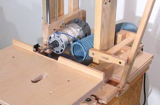 Slot mortiser
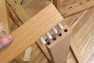 Joining with dowels
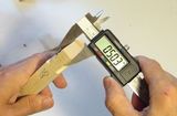 Accuracy of mortise and tenon joints
Some reader built tenon jigs:
Back to my Woodworking website
![]()