Tracy Landon's horizontal boring machine
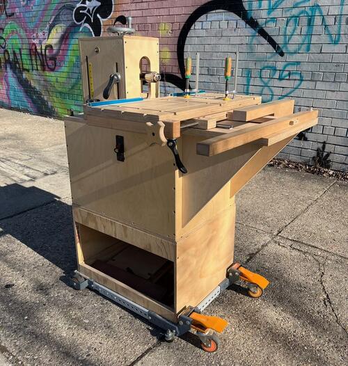 Back in 2018 I designed and built my own horizontal boring machine.
Several years later after about a dozen modifications to my original
design and with the creation of some registration accessories, it’s finally
working as reliably as I think one can hope for.
Back in 2018 I designed and built my own horizontal boring machine.
Several years later after about a dozen modifications to my original
design and with the creation of some registration accessories, it’s finally
working as reliably as I think one can hope for.
I had longed for something like this for a while prior, I first saw the video
on yours at least a year beforehand but it wasn’t until the disposal of my old
Sears bandsaw that I had a motor I could use, which was really my only
foundation for the design. I didn’t have an X-Y milling table like yours
employs, so the basis for all linear sliding motion is aluminum miter slot
bars and runners, available from Peachtree Woodworking. Its main drawback
is that it has a bit of play, which I’ve reduced as much as I can but to
try to further reduce tolerances would cause excessive friction. But overall
its easy to work with and offers enough accuracy for me; linear bearings and
shafts would have been more expensive than buying a Domino joiner.
The above engineering choice along with the wood construction limits the
capacities of the machine to small and medium sized furniture parts. Long,
heavy pieces like bed rails or passage door stiles need additional outboard
support to be drilled accurately or else they will act like a lever and pull
the cross slide table that it’s clamped down to upwards slightly, not a huge
deal but something to bear in mind.
 The cabinet is made of 1/2” baltic birch with a 1/4” bottom panel that sits
in a groove and is screwed to the sides. This makes for an extremely rigid
housing that won’t rack.
The cabinet is made of 1/2” baltic birch with a 1/4” bottom panel that sits
in a groove and is screwed to the sides. This makes for an extremely rigid
housing that won’t rack.
 There are two separate top pieces to the cabinet which are made of much
thicker (24mm and 27mm) baltic birch, separated by a piece of maple. I’ll
refer to them as the headstock support table and the cross slide support table.
There are two separate top pieces to the cabinet which are made of much
thicker (24mm and 27mm) baltic birch, separated by a piece of maple. I’ll
refer to them as the headstock support table and the cross slide support table.
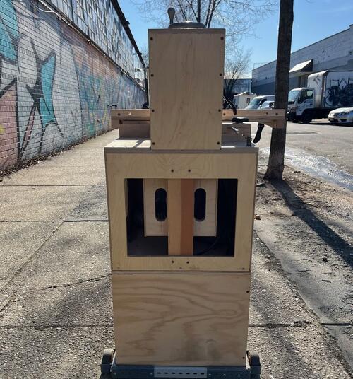
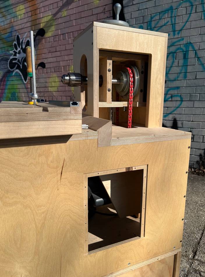
The 1hp TEFC motor sits in a mount that slides up and down, the drive belt
is tensioned simply by the weight of the motor. Power is transmitted to the
shaft via a pair of step cone pulleys which offer speeds of roughly 700, 1300,
and 2300 RPM’s. It is necessary to use a link belt due to the design of the
headstock (the whole contraption that holds the shaft and chuck); the pulley
is in between the bearing pillow blocks for maximum rigidity. To change speeds
you simply lift the motor and shift the belt to the desired sheave sizes, then
release the motor. The large rectangular hole in the cabinet that reveals the
motor is from the first iteration of the motor mount which involved a rather
cumbersome hinging mechanism, now I use the hole just to route the suction
hose out of the cabinet.
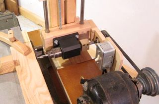
The chuck is attached to the 3/4” shaft via a motor shaft arbor that’s readily
available online, although I did have to cut the threaded stud down quite a bit.
The radial position of the washer (which comes with the arbor) behind the chuck
is critical, rotating it clockwise or counter clockwise relative to the chuck
will introduce runout. Takes a bit of trial and error with a dial indicator and
a drill blank to eliminate the runout, and in my case, some lapping of the arbor
washer. The shaft runs in regular sealed ball bearings and is secured axially
by some shaft collars and spacers. The wooden pillow blocks had blind holes for the
bearings drilled, followed by through holes for the shaft, after which they
were cut in half and screwed back together so that both halves compress the
bearings to hold them in place. Note the large black round head screws above.
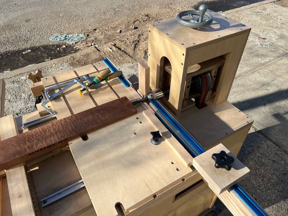
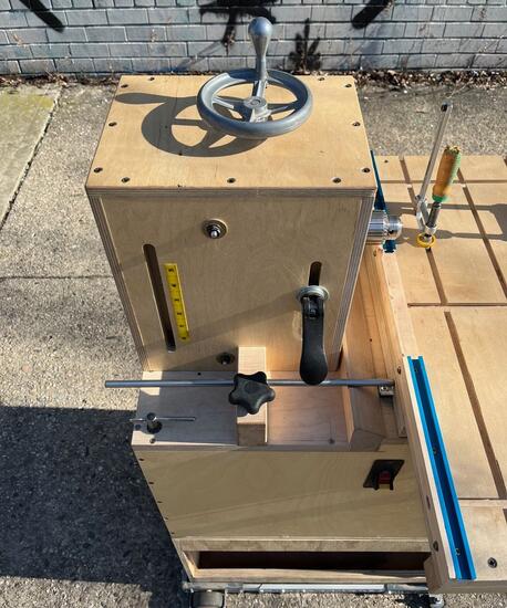 The raising and lowering of the headstock is accomplished via a 3/8-8 lead screw coupled
to a handwheel on top of the headstock housing, and its vertical path is also
maintained by a miter slot bar and runner secured to the headstock housing
via 1/4” bolts and nuts (visible from the outside in the image at left). Two
acme nuts in the headstock mesh with the lead screw, pulling it and the motor
up as the handwheel is cranked. Height is locked with the black cam lever.
A tape scale is used to indicate the height of the center of the drill above the
cross slide table, but the cursor window for the scale broke. It’s OK because
I know when the knob of the handwheel is at 3 o’clock, it is dead on the eighths
of an inch, but I’ll replace the cursor when I have a shop again. A depth stop
is accomplished by pinching a 3/8” shaft in a block of hard maple that strikes
the cross slide table.
The raising and lowering of the headstock is accomplished via a 3/8-8 lead screw coupled
to a handwheel on top of the headstock housing, and its vertical path is also
maintained by a miter slot bar and runner secured to the headstock housing
via 1/4” bolts and nuts (visible from the outside in the image at left). Two
acme nuts in the headstock mesh with the lead screw, pulling it and the motor
up as the handwheel is cranked. Height is locked with the black cam lever.
A tape scale is used to indicate the height of the center of the drill above the
cross slide table, but the cursor window for the scale broke. It’s OK because
I know when the knob of the handwheel is at 3 o’clock, it is dead on the eighths
of an inch, but I’ll replace the cursor when I have a shop again. A depth stop
is accomplished by pinching a 3/8” shaft in a block of hard maple that strikes
the cross slide table.
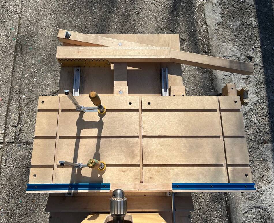
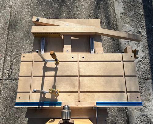 The cross slide table sits on two pairs of miter slot bars and runners. In order
to minimize play, the miter slot runners sit in very shallow grooves. This ensures
that the miter slot bars are held tight to the piece they slide upon. Obviously
it’s of utmost importance that the table components are dead flat or else the
runners will bind up, hence why they’re made of 30mm baltic birch that I flattened
with a low angle jack plane. The cross slide table is advanced towards the headstock
by means of a simple wood lever (top of image at left) bolted to the cross slide
support table and a linkage connected by some bits of 5/8” steel rod. The maximum
stroke is just shy of 6” and the lever gives a mechanical advantage of about 3:1.
The cross slide table sits on two pairs of miter slot bars and runners. In order
to minimize play, the miter slot runners sit in very shallow grooves. This ensures
that the miter slot bars are held tight to the piece they slide upon. Obviously
it’s of utmost importance that the table components are dead flat or else the
runners will bind up, hence why they’re made of 30mm baltic birch that I flattened
with a low angle jack plane. The cross slide table is advanced towards the headstock
by means of a simple wood lever (top of image at left) bolted to the cross slide
support table and a linkage connected by some bits of 5/8” steel rod. The maximum
stroke is just shy of 6” and the lever gives a mechanical advantage of about 3:1.
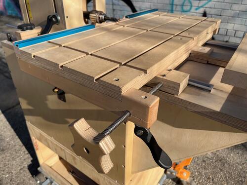 The cross slide table can move side to side 6”. The lead screw shown at left
functions as both a micro adjuster and as a lock for side to side motion.
The cross slide table can move side to side 6”. The lead screw shown at left
functions as both a micro adjuster and as a lock for side to side motion.
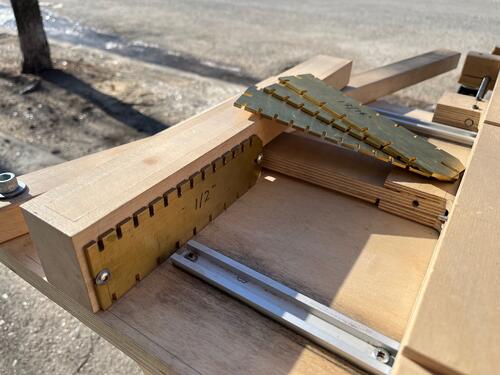 A block of maple shaped something like the state of Oklahoma can hold brass indexing
templates that mesh with a 1/8” steel pin in the edge of the cross slide table
(look closely), as well as providing a bit of extra work piece support. The
templates allow perfectly spaced holes to be drilled in parts for dowel joints,
which is the primary use of this machine.
A block of maple shaped something like the state of Oklahoma can hold brass indexing
templates that mesh with a 1/8” steel pin in the edge of the cross slide table
(look closely), as well as providing a bit of extra work piece support. The
templates allow perfectly spaced holes to be drilled in parts for dowel joints,
which is the primary use of this machine.
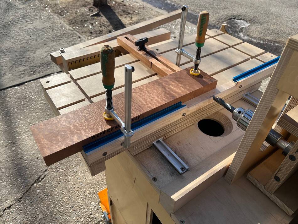
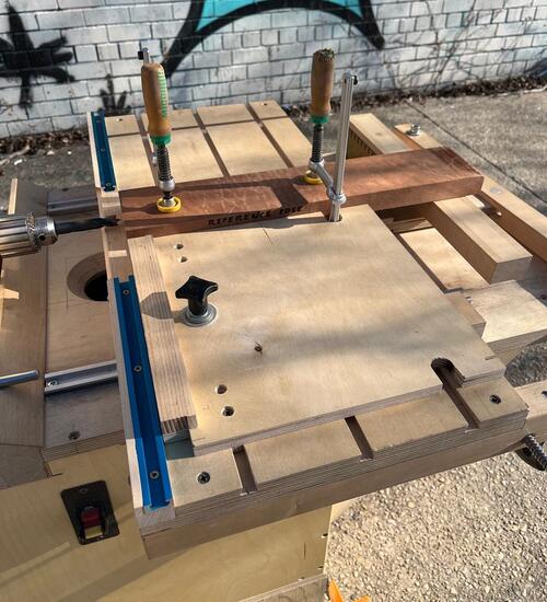 Work pieces are secured to the cross slide table via matchfit dovetail clamps.
A squaring side stop can be secured to the cross slide table for repeated drilling
of like parts, it has a dovetail key that gets pulled up by the plastic 4 lobe
knob to lock its position.
Work pieces are secured to the cross slide table via matchfit dovetail clamps.
A squaring side stop can be secured to the cross slide table for repeated drilling
of like parts, it has a dovetail key that gets pulled up by the plastic 4 lobe
knob to lock its position.
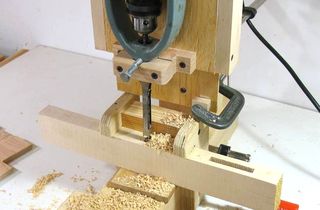
 A back stop can also be attached for drilling into parts on their face or edge
so long as they are narrow enough. Note that the matchfit clamp can be installed
from behind the fence. Also note the suction port in the cross slide support table,
this does a decent job of keeping the chips under control.
A back stop can also be attached for drilling into parts on their face or edge
so long as they are narrow enough. Note that the matchfit clamp can be installed
from behind the fence. Also note the suction port in the cross slide support table,
this does a decent job of keeping the chips under control.
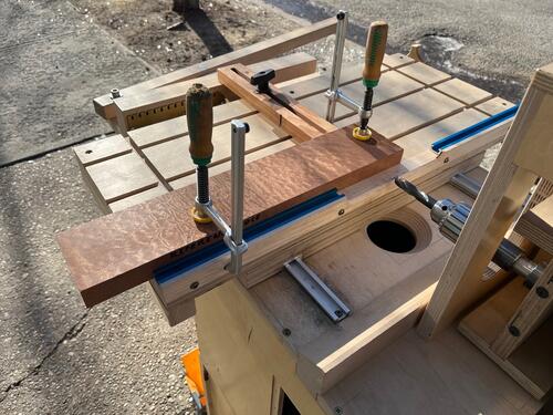
 The device shown in the image at left (blue rail extending diagonally from the bottom
right corner) records distance between the squaring side stop and the chuck so it can
be removed and repeated later, or so that it can be transferred to the other side of
the chuck as I’ve shown here. This way I can flip parts end for end, referencing the
same edge (note the sharpie on the edge of the work piece above and in previous images)
and face, while getting an identical hole pattern on both ends. Trying to reproduce
the position of the squaring side stop by going off of pencil lines on the work
piece had rarely worked out, so this was actually my most recent contribution to
the machine.
The device shown in the image at left (blue rail extending diagonally from the bottom
right corner) records distance between the squaring side stop and the chuck so it can
be removed and repeated later, or so that it can be transferred to the other side of
the chuck as I’ve shown here. This way I can flip parts end for end, referencing the
same edge (note the sharpie on the edge of the work piece above and in previous images)
and face, while getting an identical hole pattern on both ends. Trying to reproduce
the position of the squaring side stop by going off of pencil lines on the work
piece had rarely worked out, so this was actually my most recent contribution to
the machine.
The following is a bit extraneous with regards to the machine, but is informative
of how (and why) I operate it.
On Dowel Joints:
I like dowel joints because they are a bit more versatile than a mortise and tenon
in my opinion. For example, you can have dowel holes that are interlaced through the
upper end of a table leg where an apron would attach without really compromising the
integrity of the leg like a couple of mortises might do. Or, you can use dowels that
aren’t even glued in to locate two parts that need to have a knockdown function and
are held together by some other means. Dealing with joints at angles other than
90 degrees is also greatly simplified, even compound angles can be handled rather easily.
Dowels should always be glued into the part with holes in the long grain one by one,
since the end grain inside the bore will soak up the glue rapidly. Once this is complete,
glue can be applied to all of the exposed half of inserted dowels and the bores in
the end grain of the mating piece.
I also offset my dowels with more engagement in the face or edge of a part than in
the end of the mating part. The end grain inside the bores on a face or edge doesn't
have as much holding power as the all around long grain inside the bores in the end
of a piece, taking this measure makes for a stronger joint and makes it easier to
knock the joint together.
On Tooling:
For dowel joinery, a short length or regular length brad point bit works best on
relatively homogenous hardwoods. A short length drill can bore deep enough holes
for 1/2” x 4 1/2” dowels or 3/8” x 2 1/2” dowels, which are the longest of those
diameters that I keep in store. A short length regular point bit may work better
for species like southern yellow pine or red oak; I’ve found the center spur can
get pulled off course by the varying density of earlywood vs latewood.
Drills need to be very sharp. Dull drills tend to wander off course and can push
the work piece away from the fence on the cross slide table as its being drilled.
The nominal sizes of dowels aren’t necessarily accurate, the spiral pins I have
are generally a bit oversized. I use a letter V bit for my 3/8” dowels. Once you
have glue on them, getting the joint to closer becomes nearly impossible if a dry
fit takes any kind of real effort, so having a bit of clearance is necessary.
The 1/2” dowels I have are a bit leas fussy but I have a couple 12.8mm drills in
case I have any trouble with a dry fit.
 Back in 2018 I designed and built my own horizontal boring machine.
Several years later after about a dozen modifications to my original
design and with the creation of some registration accessories, it’s finally
working as reliably as I think one can hope for.
Back in 2018 I designed and built my own horizontal boring machine.
Several years later after about a dozen modifications to my original
design and with the creation of some registration accessories, it’s finally
working as reliably as I think one can hope for.


 My horizontal boring machine
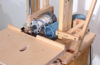 My slot mortiser
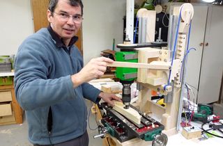 Drilling / milling machine build
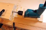 Horizontal boring jig
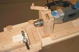
 Hollow chisel mortiser experiments
 Shawn Haven's mill-drill table based slot mortiser
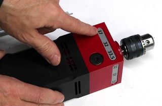 A square drill