 I previously experimented with using
temperature sensors to measure the temperature rise in the house wiring
to determine when high-current appliances are on.
I previously experimented with using
temperature sensors to measure the temperature rise in the house wiring
to determine when high-current appliances are on.
I previously experimented with using
temperature sensors to measure the temperature rise in the house wiring
to determine when high-current appliances are on.
This approach was relatively easy, but it only works for currents above 4 Amperes, takes a few minutes to get a measurable temperature rise, and can be fooled by changes in ambient temperature.
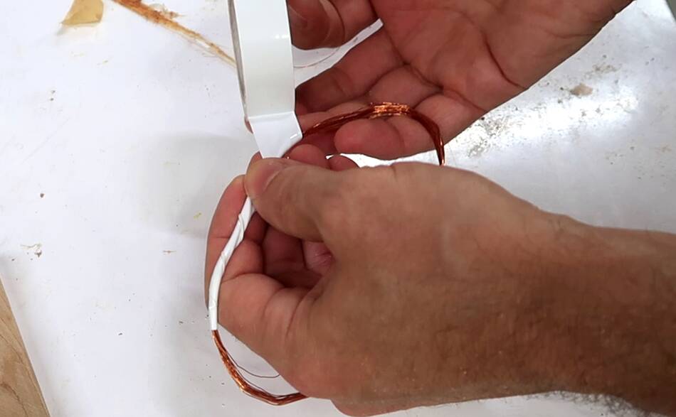
 So I had the idea of using a coil to inductively pick up the magnetic
field from the current flowing through the wire. I make a small loop
with five turns of wire.
So I had the idea of using a coil to inductively pick up the magnetic
field from the current flowing through the wire. I make a small loop
with five turns of wire.
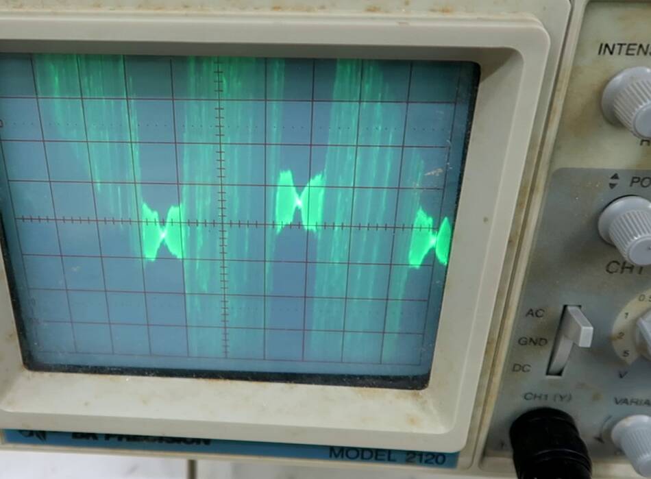
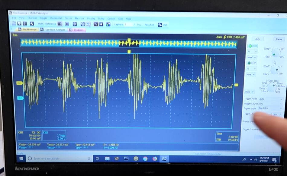
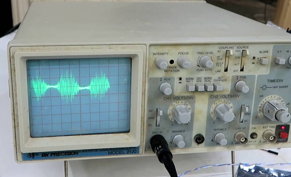 Checking it with an oscilloscope, this picked something up, but it was
a very noisy signal.
Checking it with an oscilloscope, this picked something up, but it was
a very noisy signal.

 The way this works is the coil around the wire picks up some of the magnetic
field produced by the current in the wire. The strength of the magnetic field is
proportional to the current in the wire, but the induced voltage in the wire
is a function of the rate of change of the magnetic field.
The way this works is the coil around the wire picks up some of the magnetic
field produced by the current in the wire. The strength of the magnetic field is
proportional to the current in the wire, but the induced voltage in the wire
is a function of the rate of change of the magnetic field.
While the line current is mostly a 60 Hz sine wave, it also has a lot of higher frequency noise on it, caused by dimmer switches and most modern "switching" type power supplies, including those in computers, small power adapters and LED light bulbs. These high frequency components really get amplified when measuring the rate of change of current instead of the current itself.
 I also wasn't getting a very strong signal, so I made another coil, this one
a bit longer and with ten turns on it.
I also wasn't getting a very strong signal, so I made another coil, this one
a bit longer and with ten turns on it.
 This made for a bigger signal, but still very noisy.
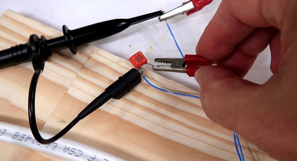 So I had the idea of dampening the oscillations by connecting a small
condenser parallel to the coil. This one is a 0.33 µF condenser.
So I had the idea of dampening the oscillations by connecting a small
condenser parallel to the coil. This one is a 0.33 µF condenser.
 But to my surprise, connecting this one only made the problem worse!
thinking about it a bit, my coil acts as an inductor. Connecting a condenser parallel to it makes an LC circuit that resonates.
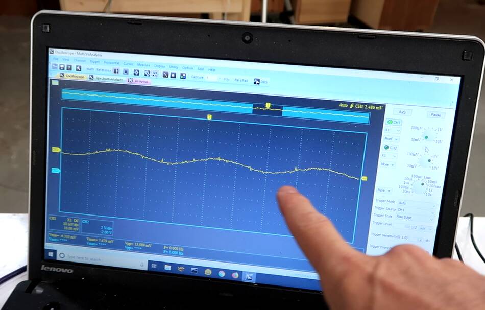
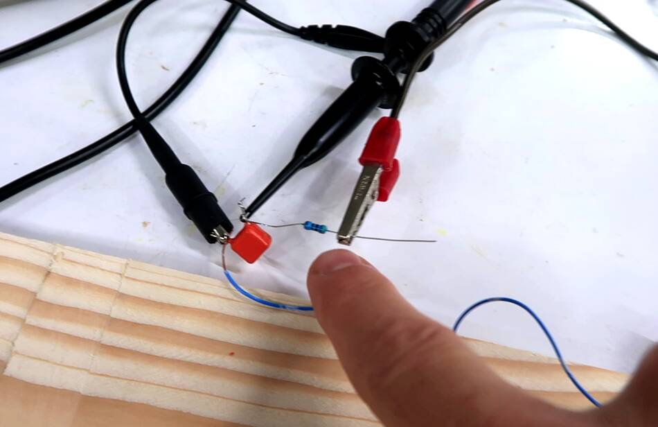 so I added a 4.7 kΩ resistor in series with the coil. This effectively
makes my circuit an RC filter with a 1.5 ms time constant.
so I added a 4.7 kΩ resistor in series with the coil. This effectively
makes my circuit an RC filter with a 1.5 ms time constant.
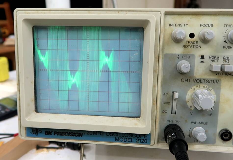
 And that cleaned the signal right up to make for a nice 60 Hz sine wave.
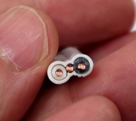
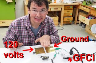
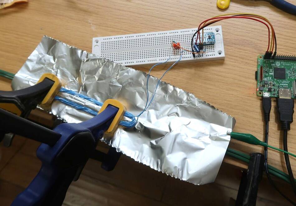 But I was also getting some signal coming through even without any current
flowing. I realized this might be capacitive coupling between the wire's
conductors and my coil. A grounded piece of tinfoil between the wire and my
coil reduced the noise.
But I was also getting some signal coming through even without any current
flowing. I realized this might be capacitive coupling between the wire's
conductors and my coil. A grounded piece of tinfoil between the wire and my
coil reduced the noise.
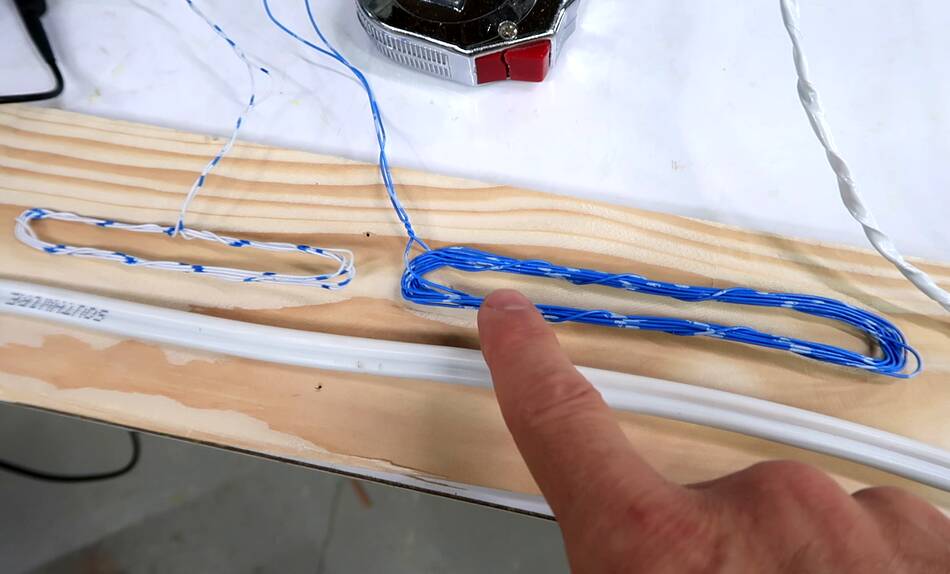
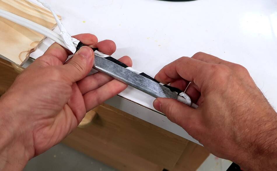
 So I made another sensing coil. This one with 20 turns of magnet wire
(much thinner), wrapped in electrical tape.
So I made another sensing coil. This one with 20 turns of magnet wire
(much thinner), wrapped in electrical tape.
 Then wrapping tinfoil around the coil as a shield, with a copper wire behind
the tinfoil to make sure it was all well grounded. I made sure not to
complete the loop with my shielding so it wouldn't "short circuit" the coil.
Then wrapping tinfoil around the coil as a shield, with a copper wire behind
the tinfoil to make sure it was all well grounded. I made sure not to
complete the loop with my shielding so it wouldn't "short circuit" the coil.
Then another layer of tape on top of that to hold it all together.
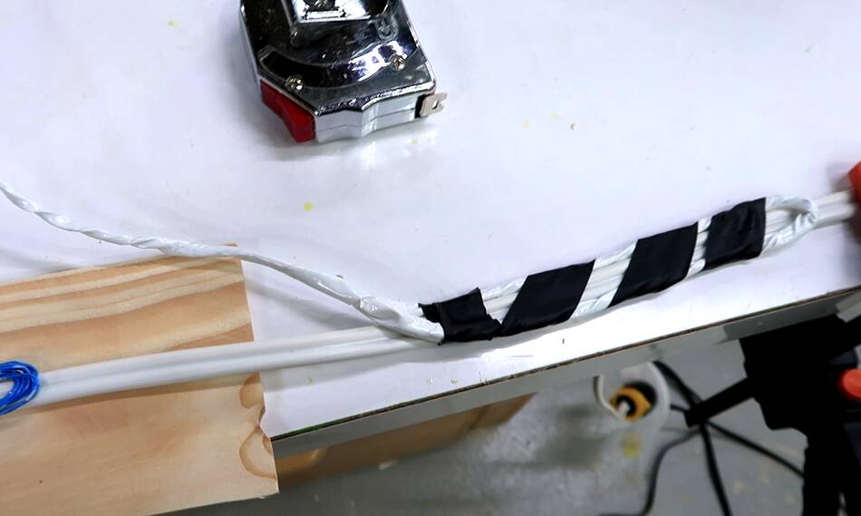 And here is my new sense coil, taped to the wire with some black electrical
tape.
And here is my new sense coil, taped to the wire with some black electrical
tape.
 This gave me enough of a signal that I could use my
cheap USB digital
oscilloscope
with it. This scope isn't as sensitive or as fast as my analog scope, but it
shows up much better on video, and is more useful for measuring
waveforms.
This gave me enough of a signal that I could use my
cheap USB digital
oscilloscope
with it. This scope isn't as sensitive or as fast as my analog scope, but it
shows up much better on video, and is more useful for measuring
waveforms.
 Just out of curiosity, I bypassed the 4.5 kΩ resistor to examine the
resonance I was seeing.
Just out of curiosity, I bypassed the 4.5 kΩ resistor to examine the
resonance I was seeing.
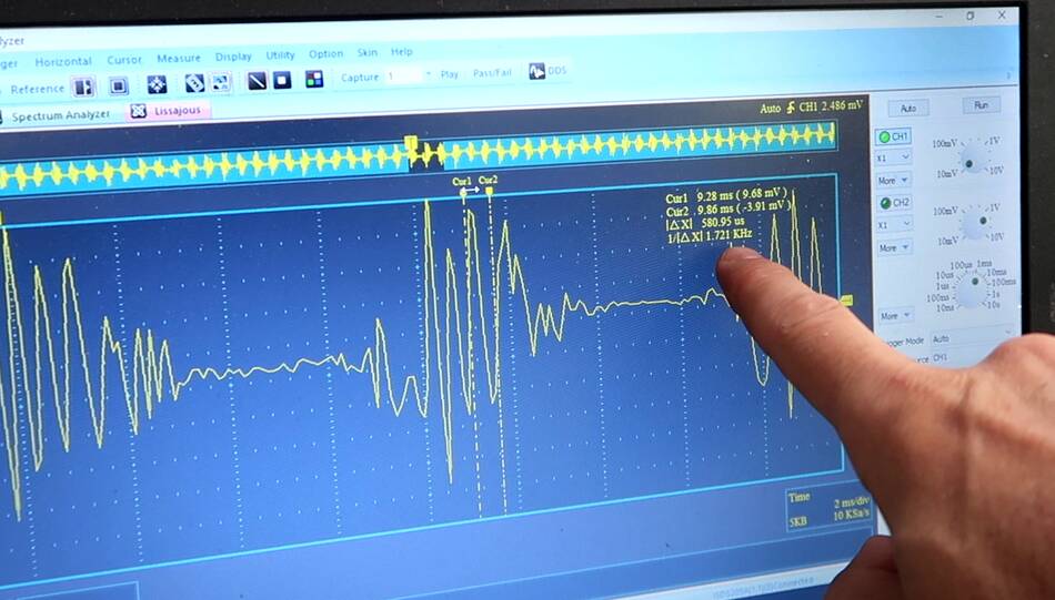 With the 20 turn coil, it had a tendency to resonate at 1.7 kHz. Of course,
the resistor already got rid of the resonance.
With the 20 turn coil, it had a tendency to resonate at 1.7 kHz. Of course,
the resistor already got rid of the resonance.
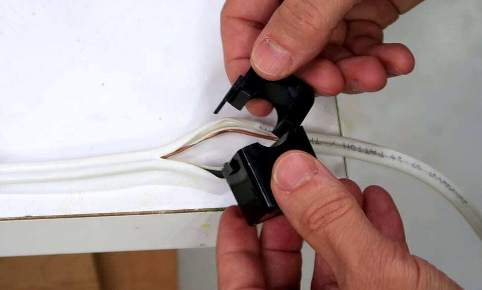 An alternative to using my coil would be one of these clamp on current
transformers. All I have to do is split the wire and clamp it around one
current carrying conductor.
An alternative to using my coil would be one of these clamp on current
transformers. All I have to do is split the wire and clamp it around one
current carrying conductor.
But the whole idea was to do it without modifying the house wiring. If I put the current transformer around the whole wire, the current flowing back through the other conductor cancels everything out because all the current flowing one way in one conductor flows the opposite direction in the other.
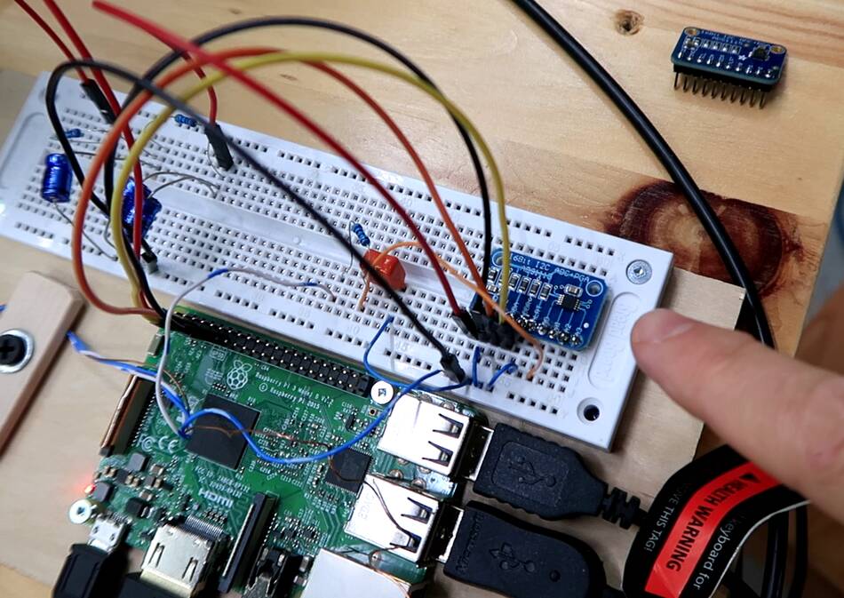 To get the signal into the computer, I used an ADS1115 A/D converter. I got
this one quite cheaply off of eBay.
To get the signal into the computer, I used an ADS1115 A/D converter. I got
this one quite cheaply off of eBay.
But I got fairly noisy readings sometimes. Eventually I realized the noisy signals were a function of what else I was running on the raspberry Pi computer. I had powered the A/D converter off the Raspberry Pi's power, and the raspberry Pi's power supply can be quite noisy, so I added two stages of RC filtering between the Raspberry Pi and my A/D converter. That cleaned up the readings considerably.
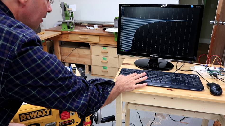
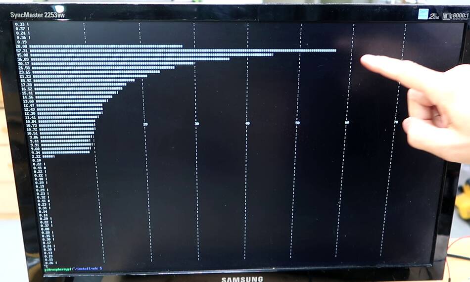
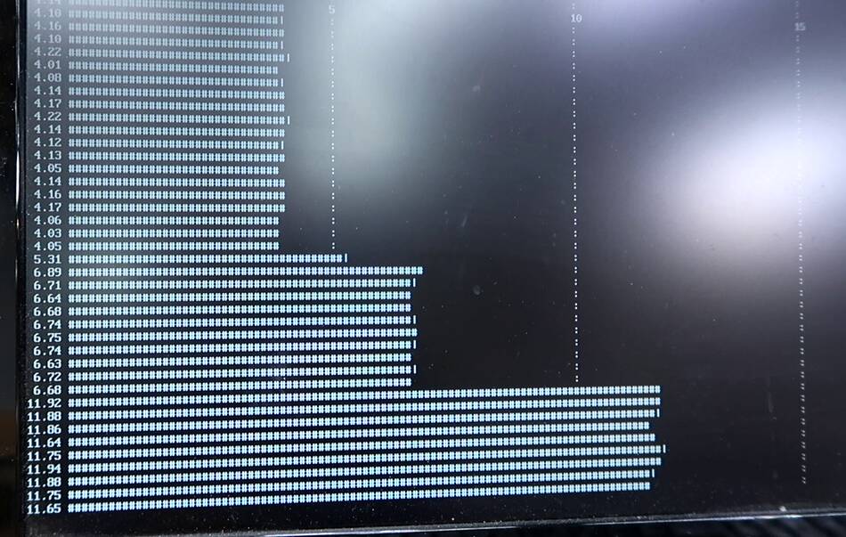 I wrote a program to continuously sample the voltage, correlate it to a 60 Hz
sine wave to cut down on noise, and make an ASCII bar graph of the current,
printing that out several times per second.
I wrote a program to continuously sample the voltage, correlate it to a 60 Hz
sine wave to cut down on noise, and make an ASCII bar graph of the current,
printing that out several times per second.
At left, with an oil filled space heater connected, switching the heater between its three levels. The highest setting draws 11.8 amperes.
I calibrated my program to match the readings from my Kill-A-Watt power meter.
 But this "16 bit" A/D converter turned out to be not the real thing, only a
mostly compatible Chinese 12-bit imitation.
So I bought another ADS1115 A/D converter from Adafruit.com.
This one cost ten times as much, but it was an actual 16 bit A/D converter.
When buying parts cheaply off eBay, Amazon, or AliExpress, you usually end
up with a Chinese clone of it, not the real thing.
But this "16 bit" A/D converter turned out to be not the real thing, only a
mostly compatible Chinese 12-bit imitation.
So I bought another ADS1115 A/D converter from Adafruit.com.
This one cost ten times as much, but it was an actual 16 bit A/D converter.
When buying parts cheaply off eBay, Amazon, or AliExpress, you usually end
up with a Chinese clone of it, not the real thing.
Surprisingly, I wasn't able to get any more sensitivity out of this one though. The imitation converter was able to read substantially faster. And with lots of samples and correlating to 60 Hz, I was for the most part able to make up for the missing bits.
 I also made an iron sleeve to go around the coil and wire.
This more than doubles the sensitivity.
I also made an iron sleeve to go around the coil and wire.
This more than doubles the sensitivity.
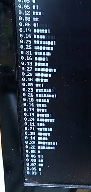 At right, readings while plugging in and then unplugging my iPad from the
charger. I can bare;u see the 0.1 ampere change in current from that.
At right, readings while plugging in and then unplugging my iPad from the
charger. I can bare;u see the 0.1 ampere change in current from that.
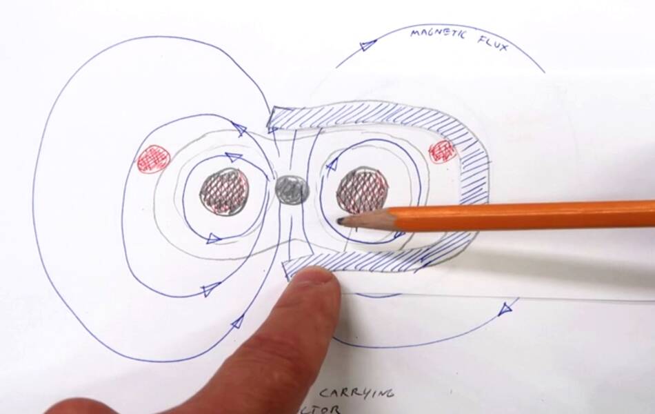 The way this works is that the iron is much more magnetically permeable
than the air, so it increases the amount of magnetic flux I get, which
in turns induces more voltage
in my sense coil.
The way this works is that the iron is much more magnetically permeable
than the air, so it increases the amount of magnetic flux I get, which
in turns induces more voltage
in my sense coil.
But the iron introduces nonlinearities of hysteresis and saturation. So unless I want to sense small currents, it's better to not use that iron sleeve.
 I built this set-up to measure short peaks in currents, such as when I turn
on my thickness planer. My set-up
indicated that this planer draws over 70 amperes the instant it's turned on.
I built this set-up to measure short peaks in currents, such as when I turn
on my thickness planer. My set-up
indicated that this planer draws over 70 amperes the instant it's turned on.
This seemed unbelievable, but if I connected three space heaters at the same time, it read that correctly. Checking the DC resistance of the planer on the plug, my ohm meter read just 1.1 ohms, and the probes touched together already read 0.2 ohms, so that made the 70 amperes starting surge more plausible.
 I checked "12 amp" my circular saw. This one peaked at over 55 amperes on starting.
 I was surprised these currents didn't pop the breaker instantly. My next experiment
was to have both turned on and plugged into a 3-way plug, and plug that in to have
them both start the same instant. That read over 100 amperes, and yet the breaker
didn't pop. I then added more and more tools, connecting the planer, circular saw,
and two bandsaws and plugging it in. Current peaked at over 140 amperes, but the
breaker did not pop. Finally, adding my jointer to it, the breaker did pop.
I was surprised these currents didn't pop the breaker instantly. My next experiment
was to have both turned on and plugged into a 3-way plug, and plug that in to have
them both start the same instant. That read over 100 amperes, and yet the breaker
didn't pop. I then added more and more tools, connecting the planer, circular saw,
and two bandsaws and plugging it in. Current peaked at over 140 amperes, but the
breaker did not pop. Finally, adding my jointer to it, the breaker did pop.
Of course, the breaker will pop at close to 15 amperes if the current is drawn for long enough to heat up the wire, but I was interested in what current it takes it to pop instantly.
Looking up trip curves for circuit breakers, requiring a current over 10x the rated current to trip the breaker instantly is fairly typical.
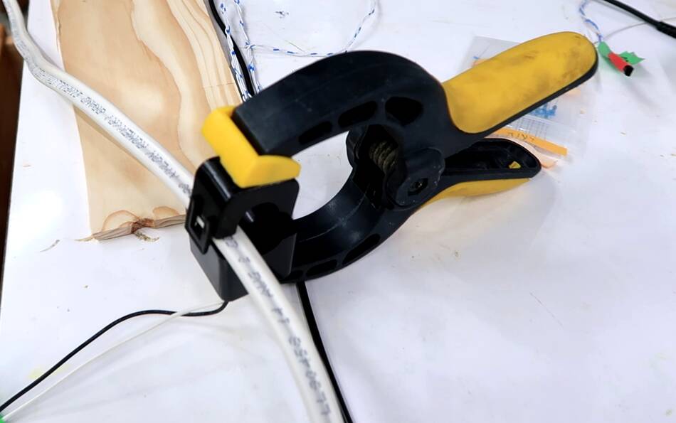 And after that, I had the idea of just clamping the clamp-on current transformer
so that its poles were roughly between the wires. This gave me a much better signal
than my homemade coil. Of course, it changes the behaviour of the current transformer
by quite a bit, so calibrating it for that configuration is necessary.
And after that, I had the idea of just clamping the clamp-on current transformer
so that its poles were roughly between the wires. This gave me a much better signal
than my homemade coil. Of course, it changes the behaviour of the current transformer
by quite a bit, so calibrating it for that configuration is necessary.
I ordered a bunch more of these current transformers to attach to some of the house wiring for monitoring. They don't cost that much, produce stronger signals (so I don't have to worry about noise as much), and I don't have to make them.
 How badly do you get zapped before you trip a GFI?
 Monitoring power use with temperature sensors
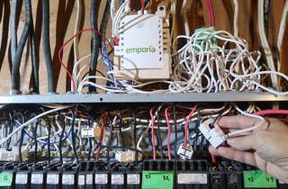 Monitoring 16 circuits at the breaker panel
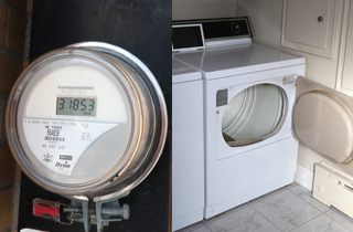 Using a utility meter to measure appliance power usage
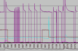 Refrigerator heat pump efficiency
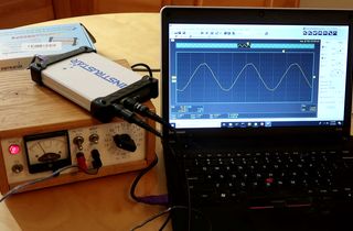 The cheapest USB scope I could find
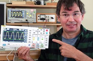 Fnirsi -1014D vs Rigol DS1202Z-E
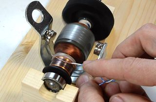 More physics related articles
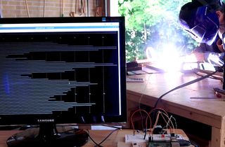 Measuring welder current with a computer
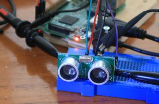 Ultrasonic distance sensor as oil level gauge
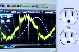 Our electrical is all wobbly, measuring power is hard
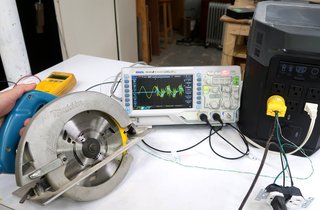 Inverters don't like power tools