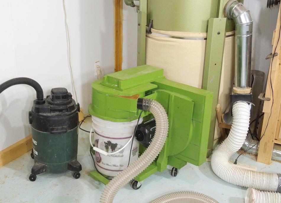
 Shop vacs make convenient mobile dust collectors, but they are very loud
and consume so much power that you often have to run them on a separate circuit.
Most shop vacs actually consume more power, and are louder than larger
dust collection units like the one in the background of this photo.
Shop vacs make convenient mobile dust collectors, but they are very loud
and consume so much power that you often have to run them on a separate circuit.
Most shop vacs actually consume more power, and are louder than larger
dust collection units like the one in the background of this photo.
So I set out to try to build a small dust collector to be quieter and lower power than a shop vac.
I don't have any experience designing blowers or cyclones, the project involved a lot of experimentation. In this article, I'll focus on the blower.
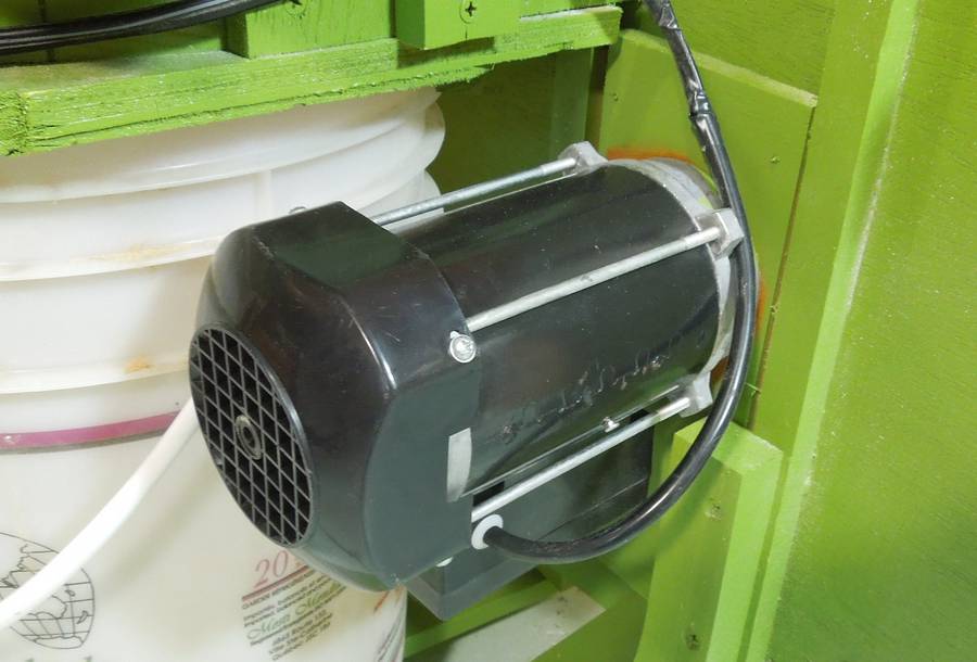
 I was to some extent inspired by this motor/blower unit that I bought used
at a surplus store years ago. This unit has just a 1/3 HP motor, yet it
blows almost as hard as a shop vac. So I figured, 1/3 HP should be sufficient.
I was to some extent inspired by this motor/blower unit that I bought used
at a surplus store years ago. This unit has just a 1/3 HP motor, yet it
blows almost as hard as a shop vac. So I figured, 1/3 HP should be sufficient.
It was tempting to use this blower, but I didn't want my dust collector based on a part that I had no idea how to obtain if I needed another one. Besides, this blower has been just too handy for stuff like my wasp sucker or here
 So I used a 1/3 HP 3500 RPM motor from a tile saw that I picked out of a dumpster.
I have seen 1/3 HP tile saws on sale new for as little as $50, much less than
it would cost to buy a 1/3 HP motor alone.
So I used a 1/3 HP 3500 RPM motor from a tile saw that I picked out of a dumpster.
I have seen 1/3 HP tile saws on sale new for as little as $50, much less than
it would cost to buy a 1/3 HP motor alone.
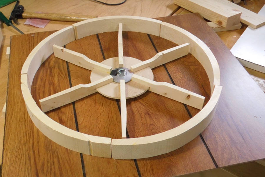
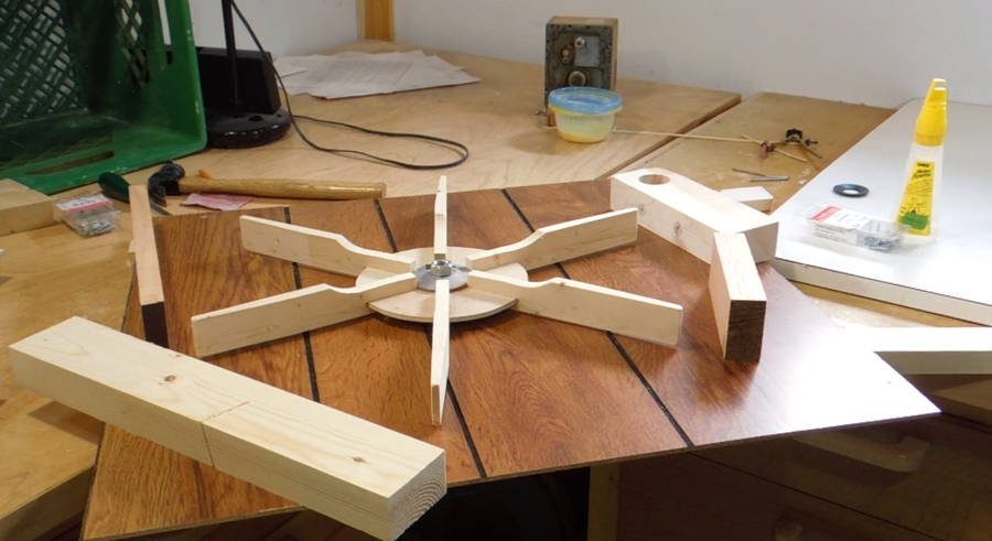 I made a six-bladed impeller out of some pieces of pine and some 1/4"
plywood. I mounted this impeller on the motor shaft using the
mounting flanges that previously held the saw blade.
I made a six-bladed impeller out of some pieces of pine and some 1/4"
plywood. I mounted this impeller on the motor shaft using the
mounting flanges that previously held the saw blade.
Plugging it in, I found that the motor was only turning a few hundred RPM. The air resistance of the impeller was too high a load for the motor, so it never got up to speed.
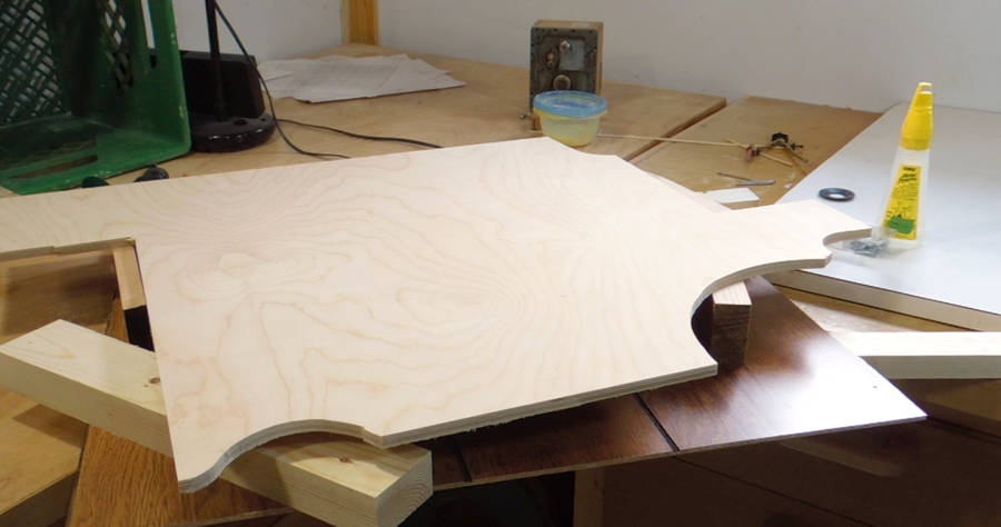 Placing a scrap of plywood over the impeller helped it run faster.
The plywood prevented "fresh air" from getting pulled in from
the middle of the impeller, so that the impeller could just push the
same air just round and round. But even this way, the impeller
was too much load for the motor.
Placing a scrap of plywood over the impeller helped it run faster.
The plywood prevented "fresh air" from getting pulled in from
the middle of the impeller, so that the impeller could just push the
same air just round and round. But even this way, the impeller
was too much load for the motor.
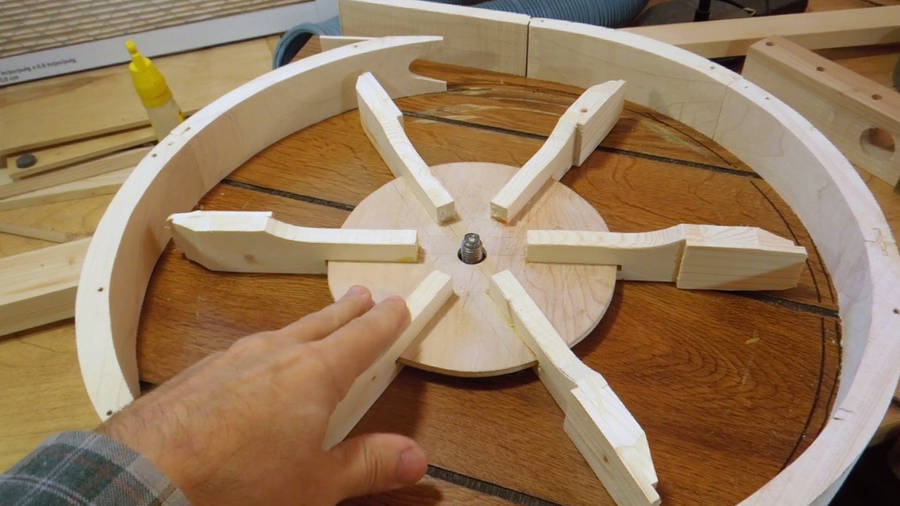
 I shortened the blades, made a circular housing for the impeller,
and covering that with a sheet of
plywood, I was finally able to get the motor to run at full speed.
I shortened the blades, made a circular housing for the impeller,
and covering that with a sheet of
plywood, I was finally able to get the motor to run at full speed.
I thought a bit about what would happen if one of these blades came off and shot at me. But with the motor spinning at 3500 RPM, and the center of mass of the blades maybe around 14 cm from the hub, the blades themselves are only moving at about 50 meters/second, or about 185km/h (115 MPH). A light piece of pine at that speed wouldn't make it through the enclosure and, even if it did, it's too light to cause serious injury.
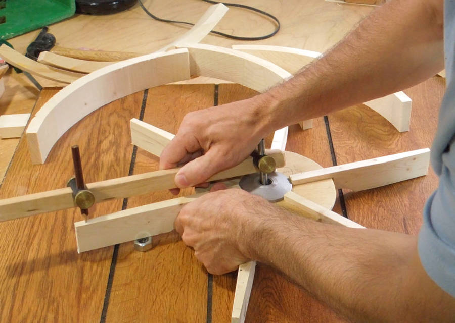 I deliberately made the impeller with longer blades,
so I could cut them shorter as needed. With just a 1/3 HP motor,
I didn't have enough power to spin the
blades and move air at the same time. So here's marking a shorter
radius on the blades...
I deliberately made the impeller with longer blades,
so I could cut them shorter as needed. With just a 1/3 HP motor,
I didn't have enough power to spin the
blades and move air at the same time. So here's marking a shorter
radius on the blades...
 ... so I could shorten them some more.
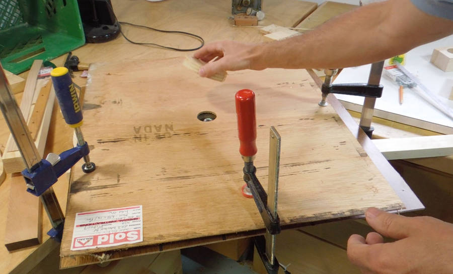 Experimenting some more with a temporary housing. Once I put an air inlet
hole in the cover sheet, I needed more power again. Covering the hole let
the motor get up to full speed, but as soon as I uncovered it, the motor
slowed down again. It made quite a howl while doing this, and that later
inspired me to experiment with building a siren.
Experimenting some more with a temporary housing. Once I put an air inlet
hole in the cover sheet, I needed more power again. Covering the hole let
the motor get up to full speed, but as soon as I uncovered it, the motor
slowed down again. It made quite a howl while doing this, and that later
inspired me to experiment with building a siren.
It's normal for radial blowers to need less torque when airflow is blocked. For both my large dust collector, as well as that 1/3 HP motor/fan unit shown earlier, the motor's power consumption drops in half when I block the air inlet.
A vacuum cleaner or shop vac won't consume much less power, when the air flow is blocked. The motor speeds up instead. But blocking the inlet on a shop vac is a bad idea - the airflow through the motor is needed to keep it from overheating.
 I was still experimenting with the size and shape of the housing. Duct tape
turned out to be surprisingly adequate for holding the housing pieces in place.
I was still experimenting with the size and shape of the housing. Duct tape
turned out to be surprisingly adequate for holding the housing pieces in place.
Once I put the top piece of plywood on, vacuum from the blower pressed the plywood pieces together hard enough to prevent the temporary enclosure pieces from sliding around.
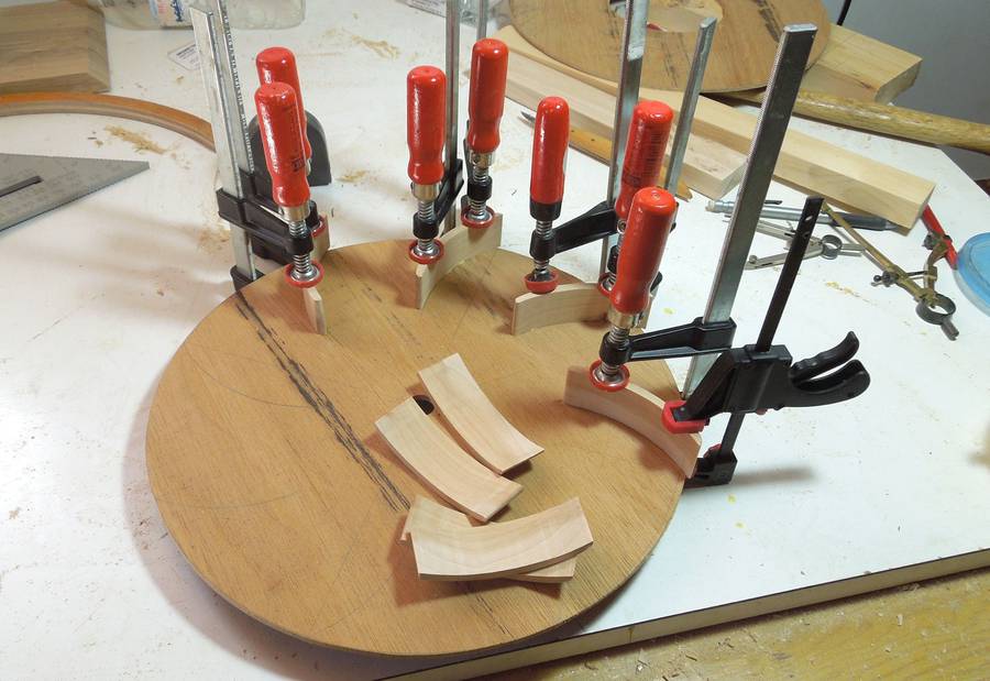
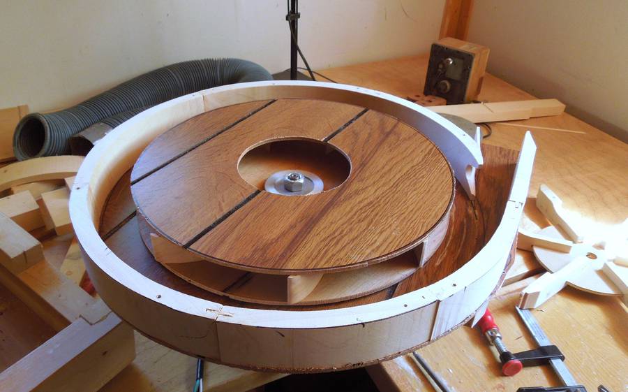
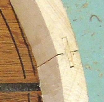 Once I had a good sense for what size impeller and enclosure I needed,
I cut hardwood pieces on the bandsaw, sanded the inside edges smooth,
and joined them end to end to make a my final enclosure.
Once I had a good sense for what size impeller and enclosure I needed,
I cut hardwood pieces on the bandsaw, sanded the inside edges smooth,
and joined them end to end to make a my final enclosure.
I also tweaked the impeller some more. I had shortened it further, but then found I didn't get enough pressure anymore. So I lengthened the blades again by gluing pieces of wood onto them.
But I wasn't happy with the performance of my blower, certainly not compared to that other 1/3 HP motor/blower unit.
 I started to wonder if the 1/3 HP rating of my tile saw motor was perhaps
on the optimistic side. I compared the winding resistance to that of the blower
unit. It was lower (better), and the running capacitor was also a larger capacity
(both motors are capacitor run motors), so by those indications, the motor
should be just as powerful.
I started to wonder if the 1/3 HP rating of my tile saw motor was perhaps
on the optimistic side. I compared the winding resistance to that of the blower
unit. It was lower (better), and the running capacitor was also a larger capacity
(both motors are capacitor run motors), so by those indications, the motor
should be just as powerful.
The other possible problem was my impeller design. On most blowers like this, the impeller is a series of curved blades sandwiched between two disks. Researching it on the web a bit, I couldn't find anything on how to design blower impellers, but found a few mentions that impellers with backward curved blades are more efficient.
 So I made some curved blades by cutting them out of a piece of hardwood
on the bandsaw, and started to assemble an eight-bladed curved blade impeller.
So I made some curved blades by cutting them out of a piece of hardwood
on the bandsaw, and started to assemble an eight-bladed curved blade impeller.
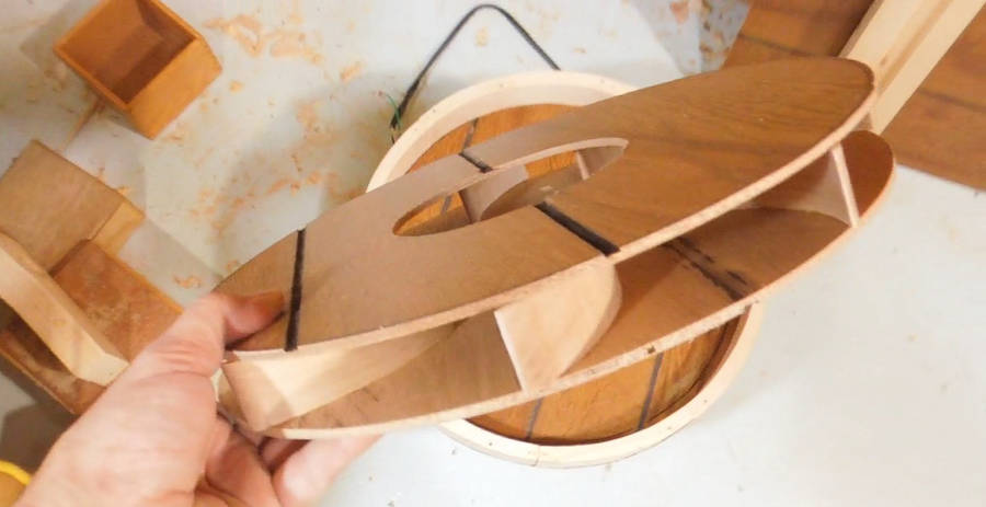
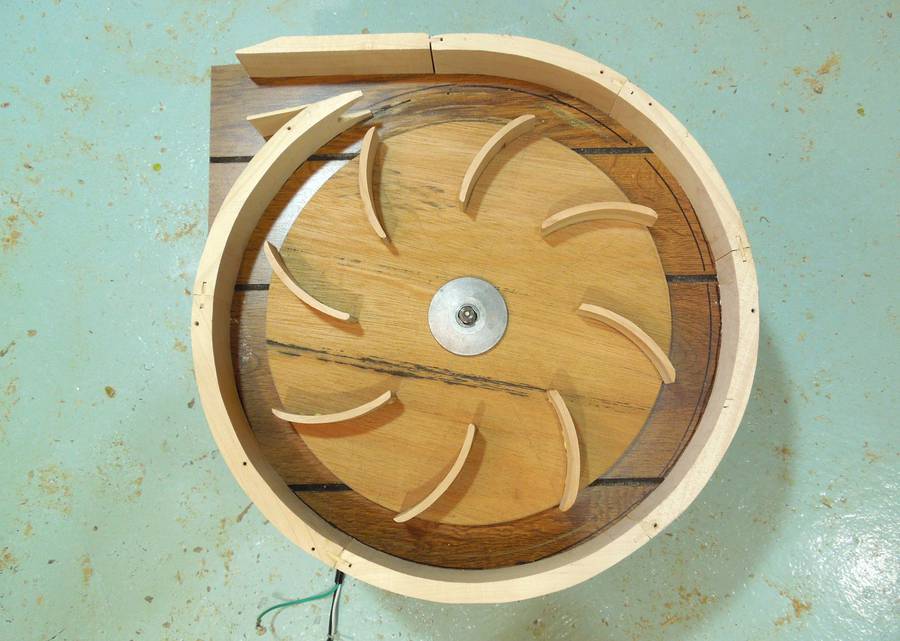 Here's the nearly complete impeller in the blower housing. The blades all
curve away from the direction of rotation.
Here's the nearly complete impeller in the blower housing. The blades all
curve away from the direction of rotation.
I think the idea is as the air moves radially outward, the backward curved blades don't "throw" the air at the tips. The air is moving fast enough around the perimeter already. But the area around the circumference of the impeller is large, so the radial component of the air speed is relatively small. So I was sceptical about whether this would make a noticeable difference.
I tried the impeller, as shown, but the centrifugal force caused the plywood backer to bend a little, and the impeller rubbed against the housing before it got up to full speed.
 So I glued on the second layer of my impeller.
 Finished impeller.
 Mounting it in the housing and spinning it up, it ran much better than my
straight bladed impeller. But I was getting a lot of shaking. My first impeller
was much lighter, and I never needed to balance it.
Mounting it in the housing and spinning it up, it ran much better than my
straight bladed impeller. But I was getting a lot of shaking. My first impeller
was much lighter, and I never needed to balance it.
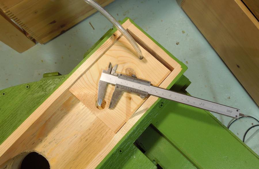
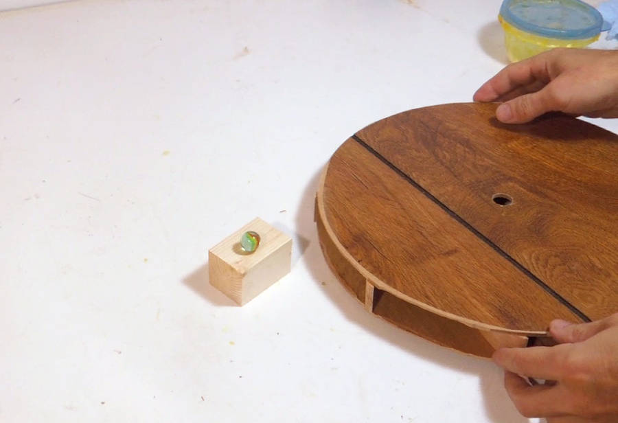 I checked the balance of the new impeller by balancing it on top of a marble
on a block of wood. The marble was just large enough not to fit through the 5/8"
hole in the impeller. Marbles are nominally around 5/8, but from
building marble machines,
I had a whole bag of marbles put aside that that would
not fit through a 5/8" hole.
I checked the balance of the new impeller by balancing it on top of a marble
on a block of wood. The marble was just large enough not to fit through the 5/8"
hole in the impeller. Marbles are nominally around 5/8, but from
building marble machines,
I had a whole bag of marbles put aside that that would
not fit through a 5/8" hole.
I balanced the impeller by cutting away at the edges a bit, sanding a bit, and finally, by gluing a small block of wood to the side that was too light. Once it balanced level on the marble, the vibration problems were also fixed.
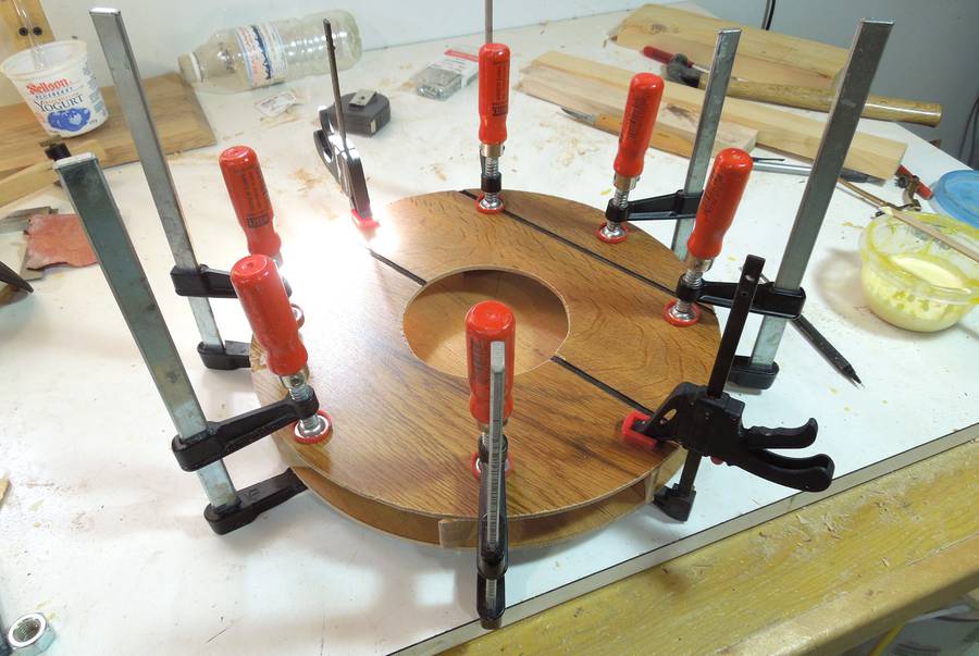
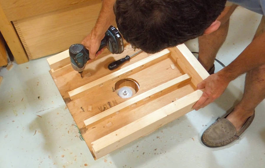 The blower is designed so that the front panel is part of the
filter box. Here's screwing the filter box to the blower.
The blower is designed so that the front panel is part of the
filter box. Here's screwing the filter box to the blower.
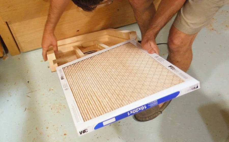 Now sliding the filter in place. I'm using a 16x21"
"Airborne microparticle recuction filter".
Now sliding the filter in place. I'm using a 16x21"
"Airborne microparticle recuction filter".
 And adding the cover for the filter enclosure.
At this point, my blower was working adequately, so after that, I focused on building the centrifugal separator for my dust collector and neglected to take more pictures. I didn't get back to characterizing the blower some more until after I built the rest of the unit and painted it.
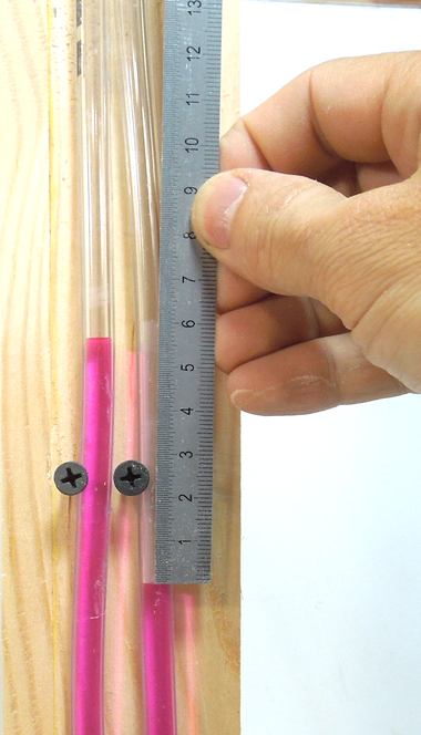
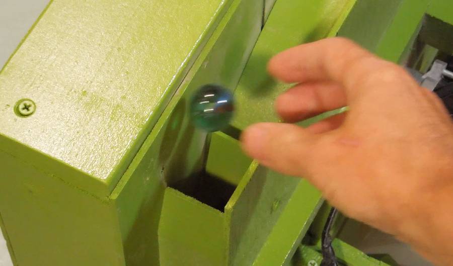 Aimed straight up, the blower is barely powerful enough to float a
25 mm glass marble above the outlet. But that is without pulling air
through any filter or cyclone.
Aimed straight up, the blower is barely powerful enough to float a
25 mm glass marble above the outlet. But that is without pulling air
through any filter or cyclone.
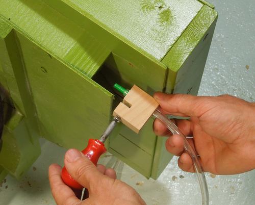 I measured the air speed at the output using a pitot
tube made from a drinking straw. I looked up pitot Tube on
Wikipedia, and made a pressure to air speed conversion table:
I measured the air speed at the output using a pitot
tube made from a drinking straw. I looked up pitot Tube on
Wikipedia, and made a pressure to air speed conversion table:
pitot tube pressure to air
speed table
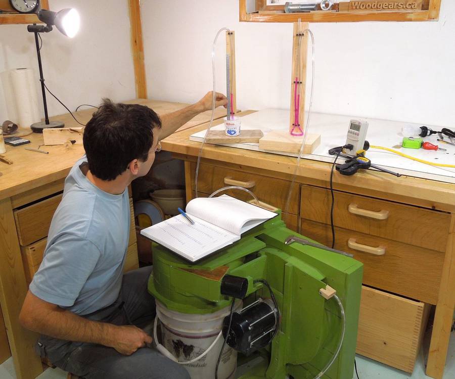
With the inlet unobstructed (no filter or separator), the motor
draws 415 watts. The pitot tube read a pressure of 132 mm of water.
That converts to
an air speed of 46 meters per second (167 km/h or 104 MPH). With the outlet
at 4x4 cm, and allowing for the air not moving at full speed towards
the edges, I estimate about 55 liters per second, or about 122 CFM.
 With the inlet blocked, maximum suction (static pressure) is 230 mm of
water, and the motor's power consumption dropped to 218 watts.
That's about the same static pressure that my big dust collector produces,
but not very much compared to a typical vacuum cleaner or shopvac.
Most vacuum cleaners produce around 1000 mm of suction when blocked.
With the inlet blocked, maximum suction (static pressure) is 230 mm of
water, and the motor's power consumption dropped to 218 watts.
That's about the same static pressure that my big dust collector produces,
but not very much compared to a typical vacuum cleaner or shopvac.
Most vacuum cleaners produce around 1000 mm of suction when blocked.
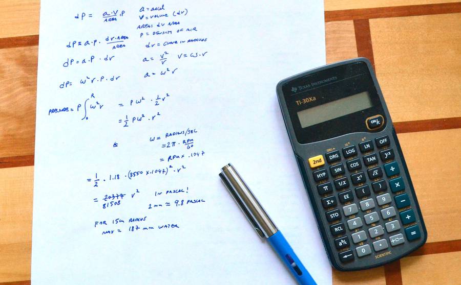 I used a bit of calculus to work out the theoretical pressure
difference of a spinning disk of air, air density and
RPM. At 31 cm diameter, that calculation came out to 200 mm of water.
I'm guessing that the air around the impeller also spinning increases
the effective size of the disk of air, hence the difference.
I used a bit of calculus to work out the theoretical pressure
difference of a spinning disk of air, air density and
RPM. At 31 cm diameter, that calculation came out to 200 mm of water.
I'm guessing that the air around the impeller also spinning increases
the effective size of the disk of air, hence the difference.
I made a spreadsheet using this formula:
Blower pressure
from RPM and impeller size
My calculus derivation was a bit messy, using P for both pressure and air density, and a to denote both area and acceleration. oops!
 I experimented with obstructing some of the flow at the inlet
by sliding a block of wood over where the air gets pulled into the filter box.
I experimented with obstructing some of the flow at the inlet
by sliding a block of wood over where the air gets pulled into the filter box.
Sliding the block back and forth, it seemed like pitot tube pressure and vacuum at the inlet (due to the obstruction) varied linearly with each other.
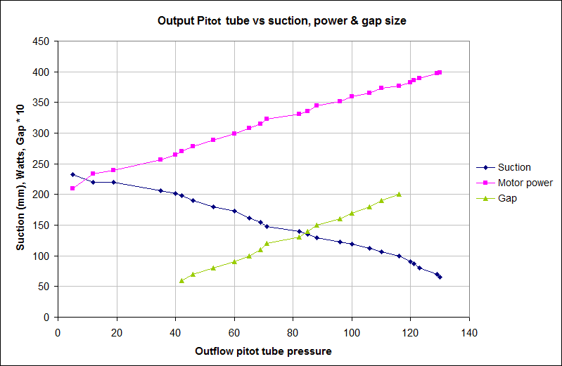 So I took a lot of readings and graphed vacuum, motor power, and air gap size
as a function of air speed as measured by pitot tube pressure.
Sure enough, these variables all related linearly!
So I took a lot of readings and graphed vacuum, motor power, and air gap size
as a function of air speed as measured by pitot tube pressure.
Sure enough, these variables all related linearly!
Note that pitot tube pressure is a function of air speed squared. But in general, for turbulent air flow, air resistance is a function of air speed squared as well. So it looks like the system of air resistance and such can be treated as a linear system as long as one uses air speed squared, or just using pitot tube pressure as the flow rate.
I find airflow and physics fascinating, and lessons learned from this dessign came handy with my next blower design experiments
Next: Building the separator