Help / how to use it / about
This free online gear template generator is designed for making scale accurate paper gear templates which you can glue onto wood and then cut out with a bandsaw. I recommend printing the gears with an ink jet printer. Even cheap ink jet printers print very scale accurate but not all laser printers are accurate.Legend (What do the fields above mean?)
| ||||||
|---|---|---|---|---|---|---|
|
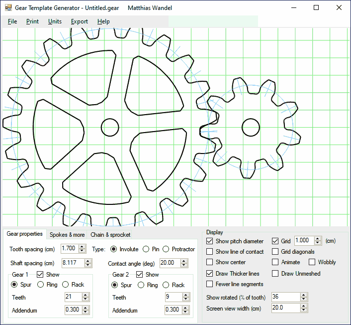
Tooth spacing Number of millimeters from one tooth to the next, along the pitch diameter.
Gear 1 teeth:
Rack&Pinion:
Measured cal distance (mm): |
Contact angle(deg): The pressure angle of the gears. For gears with smaller number of teeth, set this a bit larger, to get more sloped teeth that are less likely to jam.
Gear 2 teeth:
Two gears:
Spokes: |
Shaft hole dia. (mm): What size to draw the shaft hole. For inside (planetary) gearing, set this larger than the gear to draw a circle around the gear
Show rotated:
Print gears: |
Show pitch diameter Show the pitch diameter of the gears. The pitch diameter is the effective diameter of the gear.
Show line of contact
Show cm grid
Animate
Dividing plate mode | |||
Getting the printout to scale correctly, avoiding cropping
Different browsers print at different scales depending on browser type and printer configuration. The default scale should be correct for firefox, Internet explorer 10 and Google Chrome. If the scale is not correct (that is, the grid is not 1 cm increments), measure the distance that is labeled "If this is not 150 mm..." in millimeters and enter it in the field "Measured cal distance".
Use an ink jet printer
I recommend using an ink jet printer. The colour registration requirements of ink jet
print heads requires manufacturers to make sure the image is not stretched in either direction,
so even cheap ones are quite scale accurate. Some laser printers stretch or distort.
Printing the gear templates
To print the gear template, use the 'Print' button, instead of printing the web page from the browser.
The print button hides those parts of this page that you don't want to print, then brings up
the print window. To get the sizes specified to be correct, it's best to print a test template, and then measure
the distance between the lines at the bottom of the image, and enter that under "Measured cal distance".
Only enter this once (the value will reset). Subsequent
printouts should be scaled so that the millimeters are exact and the grid has 1 cm spacing.
 You can buy a downloadable gear template generator. More features, runs on your PC |
For gears larger than a sheet of paper, the gear is offset from center. If your gear has an even number of teeth, you can print it twice and paste the halves together. If the number of teeth is divisible by 4, you can print it 4 times and paste together. You can print gears up to 40 cm (16") in diameter this way.
The gear generator program that I created and sell
doesn't need the scale calibration, and can paginate across many pages for larger gears.
Some notes about gear design and this gear template generator
This template generator is intended for generating paper templates for cutting low precision gears from plywood, phenolic, or other suitable materials with a band saw.This gear template generator generates shapes for involute spur gears. Involute spur gears have involute shaped teeth. The best way to explain how the involute is formed is to select two gears, and check the "show line of contact" checkbox. The red line will show the line of tooth contact for the given gears, as well as the base circles. The gears work as though a string was unwound from the right gear's base circle, and wound onto the other base circle. A point on the string essentially traces the involute of the teeth. Note that the teeth always make contact along the red line, and exactly perpendicular to the line. The angle of this line with respect to vertical is the pressure angle ('Tooth angle' field in the form above)
The gear tooth generation is not perfect. Normally, one rounds the tips of gear teeth a little bit, which this program doesn't do. Also, for gears with less than about 10 teeth, and low tooth angles, it's sometimes necessary to narrow the teeth at the base (undercut) or to alter the geometry (profile shifts). So some combinations with gears of small numbers of teeth may overlap, or jam if they were real. You can check to see if the gears would overlap by selecting the 'animate' and 'two gears' checkboxes for your gears and watching them turn. My non-free gear program will automatically calculate the necessary undercut to make the gears mesh.
Ring gear / planetary motion gears
You can also generate templates for inside gearing, such as would be used for planetary
motion gears. Simply enter a negative number of teeth for one of the gears,
and that gear will be an inside gear. Select a large number for the shaft diameter when
making a template to get a circle around the gear. For more about how to work out
the number of teeth and ratio, see this note on planetary
gear ratios and calculations
Rack and pinion gearing
You can also generate rack and pinion gears. Just enter zero for the number of teeth
of a gear, and the program will draw a straight gear rack instead of a gear for
that gear.
The involute shape of gears is very important for gears that run at high speed. However,
for wooden gears with more than 12 teeth, it doesn't matter as much.
Even if you don't cut the gears with an involute shape, the template generator is still
useful as a form of protractor using
the "dividing plate mode" for dividing the circle into even intervals.
For an example of a different method of cutting gears, see my Wooden gear cutting jig
Any questions? You can email me at

|
More projects with wooden gears:
|
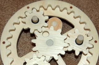 Working out planetary
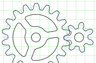 Downloadable gear template generator
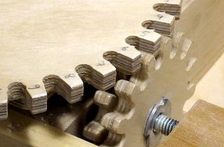 How to make gears
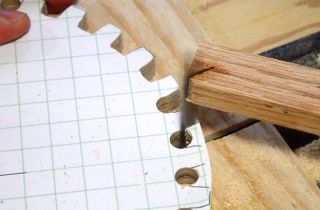 Gears with a jigsaw
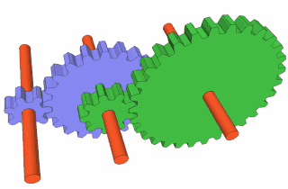 Working out gear ratios
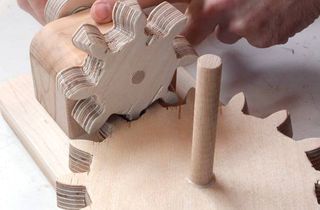 Right angle gears
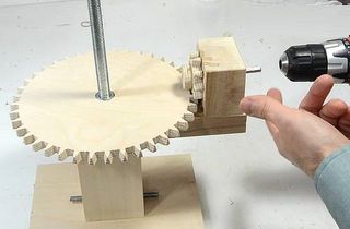 Screw jack for joint
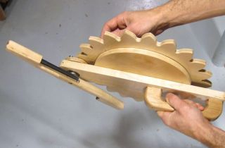 Pen shaking contraption
 Wood geared
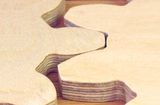 Example plywood gears
 Bandsaw vs CNC