
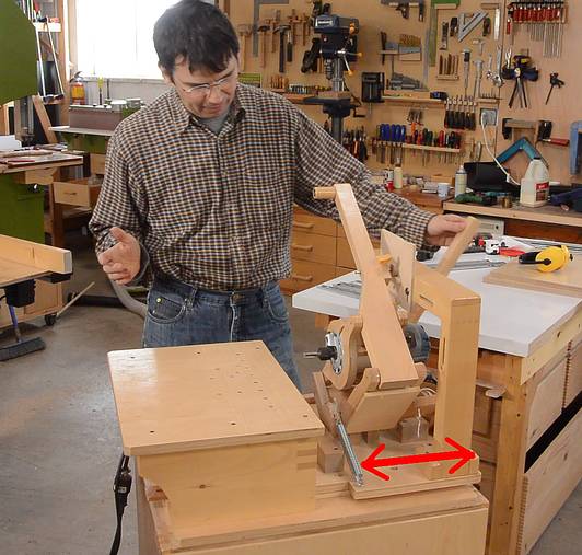
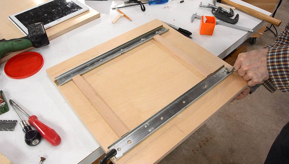
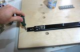
 The linear glides allow the pantograph mechanism to slide back and forth to
plunge into the work (arrows in image at right).
The slides need to be ball bearing slides of some sort or they will rack and jam
when plunging with force.
The linear glides allow the pantograph mechanism to slide back and forth to
plunge into the work (arrows in image at right).
The slides need to be ball bearing slides of some sort or they will rack and jam
when plunging with force.
I have covered this topic several times before:
In 2014 for my Pantorouter XL build
In 2010 for my first pantorouter build
In 2009 for my slot mortising machine
The main change this time is to use fewer machine screws to simplify the build and reduce costs.
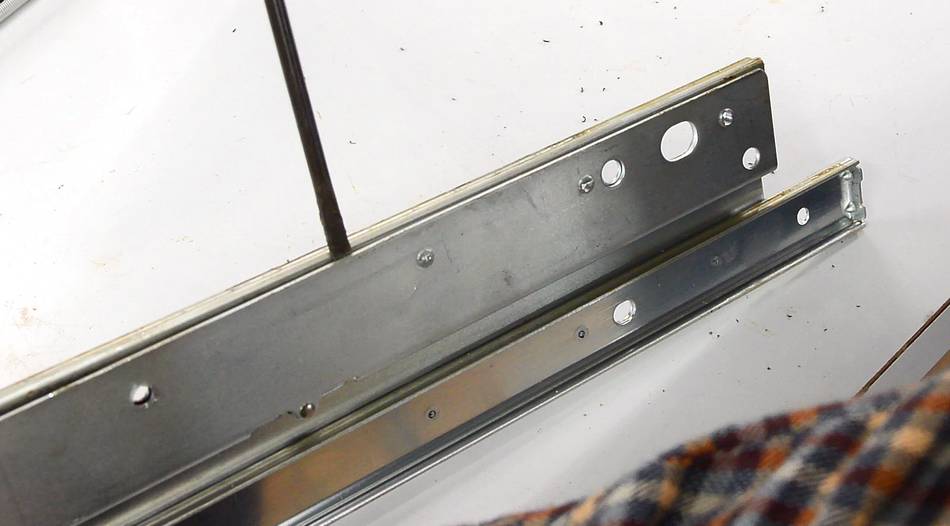
The linear glides allow the pantograph mechanism to slide back and forth to
plunge into the work (arrows in image at right).
The slides need to be ball bearing slides of some sort or they will rack and jam
when plunging with force.
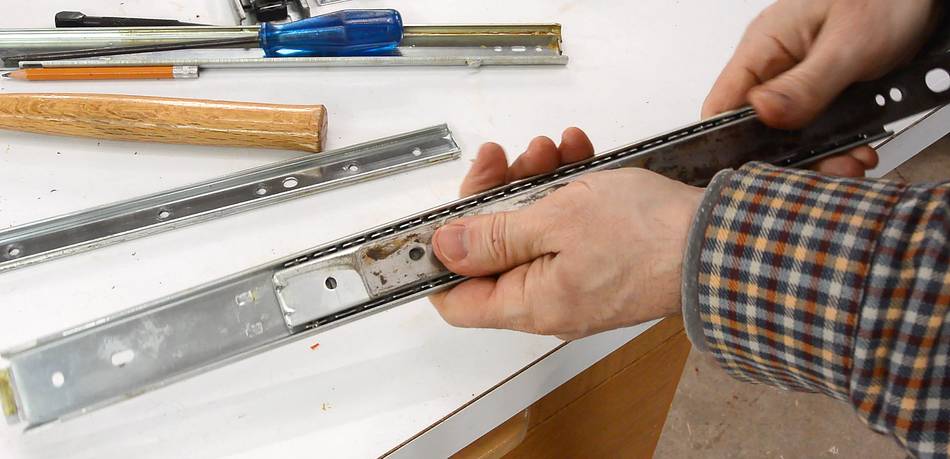
At left, from left to right:
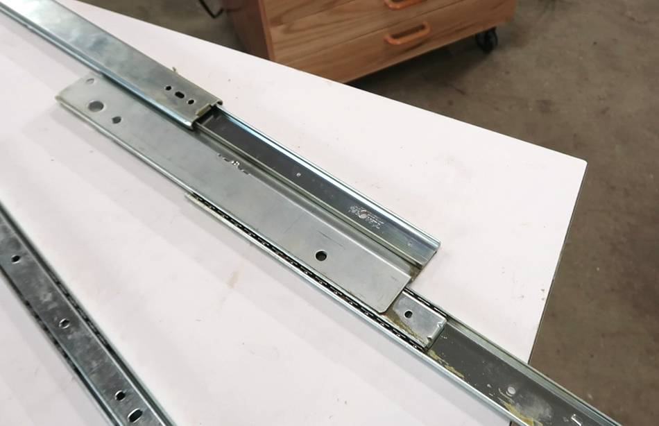 Here is the two tier slide, fully extended.
Two tier drawer slides are hard to get new. This one came out of an old desk. New slides that are suitable are center mount drawer slides and keyboard drawer slides, neither of which is full extension.
I had some of these two tier slides kicking around so that is what I used.
 Bending the tab on the outside part on the end flat allows that part to be pulled
off the slide.
Bending the tab on the outside part on the end flat allows that part to be pulled
off the slide.
 The two slides are spot welded to a Z-shaped profile. I center-punched
where the spot welds are to keep the drill bit from wandering.
The two slides are spot welded to a Z-shaped profile. I center-punched
where the spot welds are to keep the drill bit from wandering.
 Then drilled out the spot welds. The drill is larger than the spot weld,
but even so, I didn't get all of every spot weld drilled out.
Then drilled out the spot welds. The drill is larger than the spot weld,
but even so, I didn't get all of every spot weld drilled out.
 I had to do some caeful prying to get them apart, being careful not to bend
the part that I wanted to use.
I had to do some caeful prying to get them apart, being careful not to bend
the part that I wanted to use.
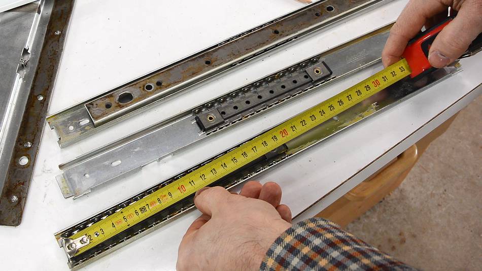 The balls for these slides are held in place by what I like to call the "ball cage".
The slide has a ball cage that is 20 cm long. A longer ball cage gives better
support but restricts the range of motion. Because I don't need that much range
of motion, there is room for a longer ball cage, ideally 28 cm long.
The balls for these slides are held in place by what I like to call the "ball cage".
The slide has a ball cage that is 20 cm long. A longer ball cage gives better
support but restricts the range of motion. Because I don't need that much range
of motion, there is room for a longer ball cage, ideally 28 cm long.
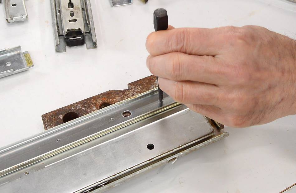
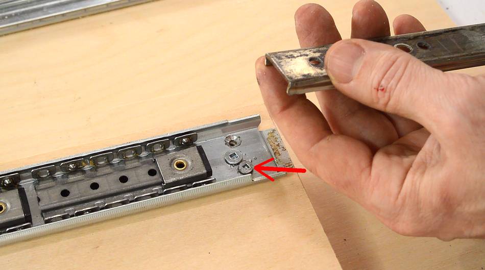
 I need to flatten these tabs (circled in red) to slide the ball cage out of the
other half of the slide. You can grind them with an angle grinder, or flatten
them with a hammer, using a piece of metal between the hammer and the tab to avoid
hitting the edge of the slide.
I need to flatten these tabs (circled in red) to slide the ball cage out of the
other half of the slide. You can grind them with an angle grinder, or flatten
them with a hammer, using a piece of metal between the hammer and the tab to avoid
hitting the edge of the slide.
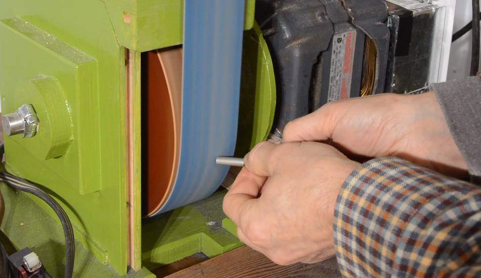
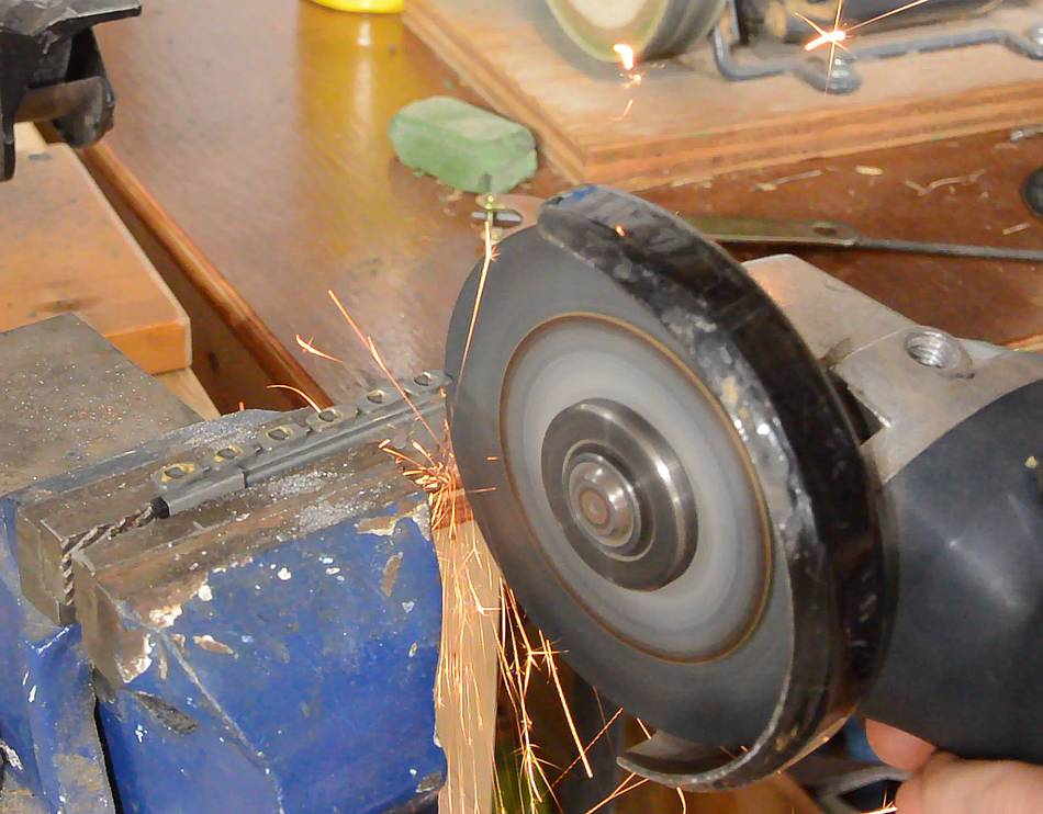 I then cut an 8 cm section off another ball cage with an angle grinder.
A hacksaw would work too.
I then cut an 8 cm section off another ball cage with an angle grinder.
A hacksaw would work too.
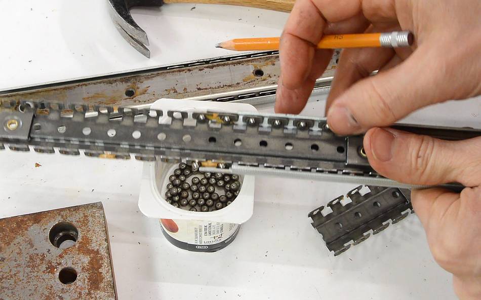 Carefully collecting the ball bearing balls as I slide the ball cage out.
 Next I assemble the slide again, but this time with just the short 8 cm long piece
of ball cage I cut off, and with just four balls on it. I slide it along to
see where the slide is loose (where I can wiggle it a bit). Using just a
short piece of ball cage makes it easier to locate where the slide is loose.
I then use a vise to squeeze the outside track a bit to bend it inward.
Next I assemble the slide again, but this time with just the short 8 cm long piece
of ball cage I cut off, and with just four balls on it. I slide it along to
see where the slide is loose (where I can wiggle it a bit). Using just a
short piece of ball cage makes it easier to locate where the slide is loose.
I then use a vise to squeeze the outside track a bit to bend it inward.
This needs to be done carefully. It's important to move the ball cage out of the way so the inner track won't get squeezed and bent, then squeeze, check, and if it's still loose, squeeze slightly harder, and repeat. I do this along the length of the entire track to make sure it isn't loose anywhere.
 Then test assembling it, but with just a few balls and no grease, because I will
need to take it apart again a few times.
Then test assembling it, but with just a few balls and no grease, because I will
need to take it apart again a few times.
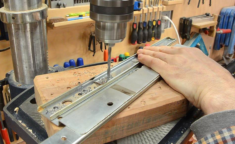
 The outer track already has holes from where I drilled it to take out the spot welds.
I used a larger drill bit to add countersinks where the screws go.
The outer track already has holes from where I drilled it to take out the spot welds.
I used a larger drill bit to add countersinks where the screws go.
It needs to be mounted with countersink screws so that the screw heads are low enough not to hit the ball cage part that slides above them.
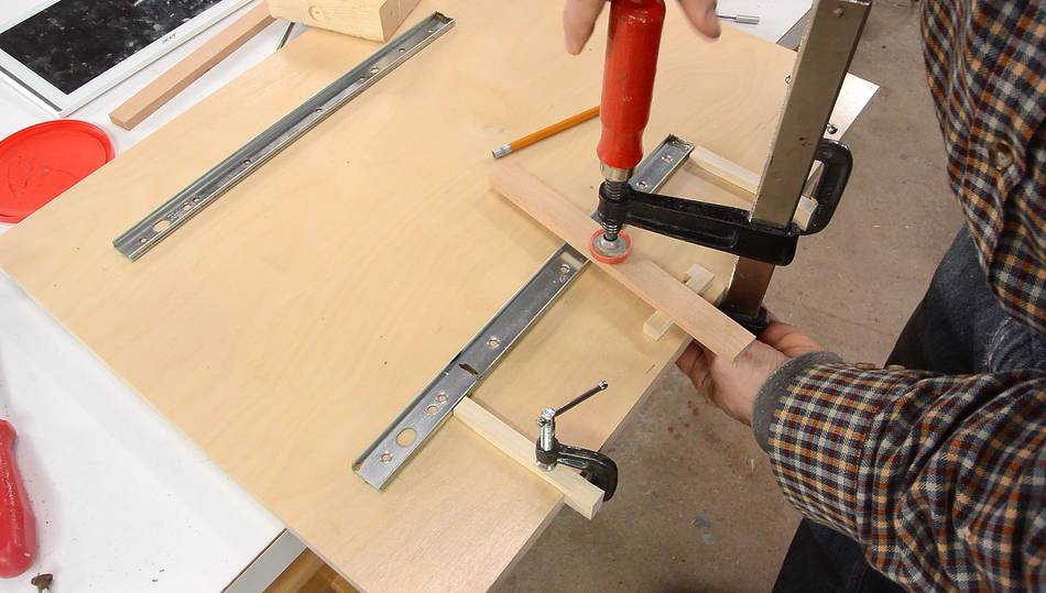
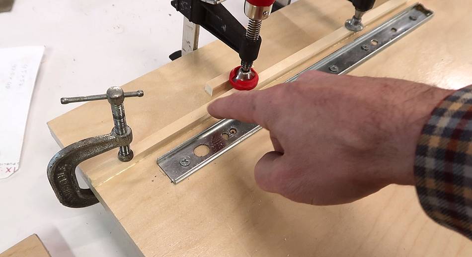
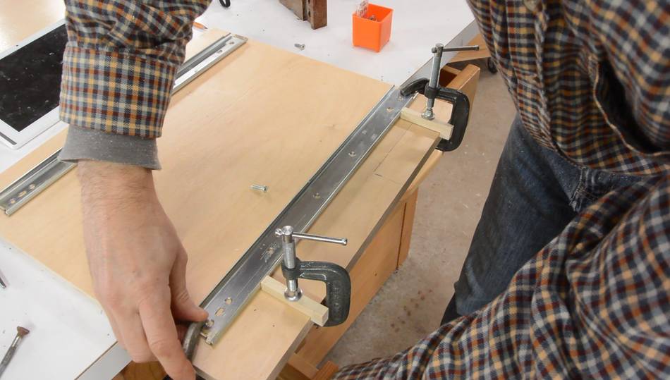 I made two spacers that hook over the edge of the wood to help me position
the track parallel to it. I made these as one spacer, then cut it down the
middle to make two spacers exactly the same length.
I made two spacers that hook over the edge of the wood to help me position
the track parallel to it. I made these as one spacer, then cut it down the
middle to make two spacers exactly the same length.
Then clamping the track on from either end.
The outer track needs to be at least 40 cm long, but there is no harm in having it a bit longer.
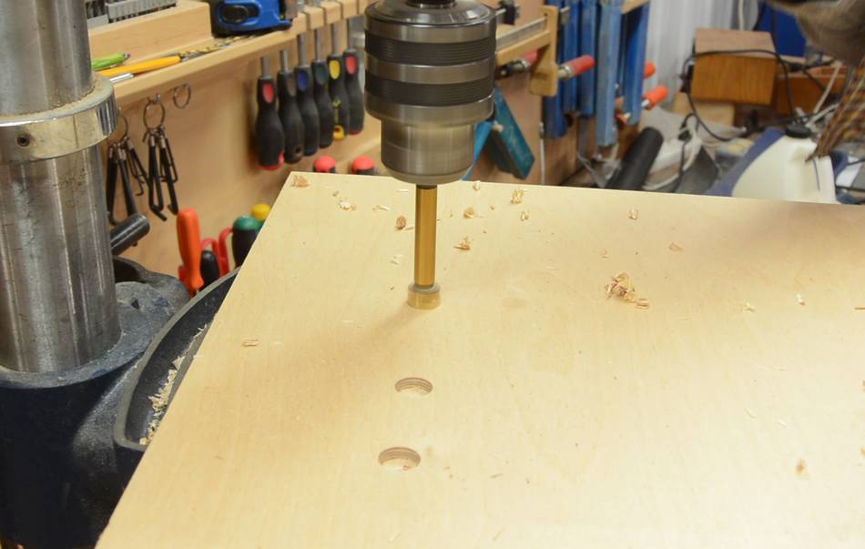
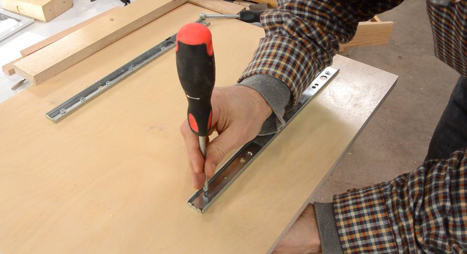
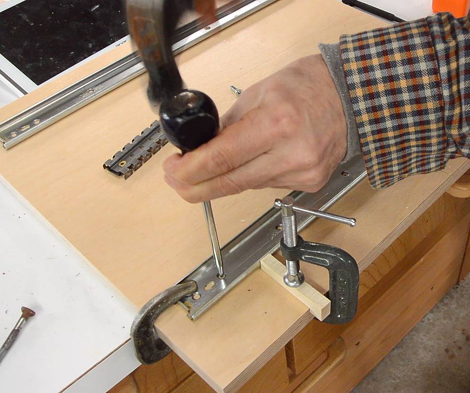 Center-punching where the mounting holes need to go using an awl, tapped
with a hammer. After that I drilled pilot holes for the screws (no picture
of that).
Center-punching where the mounting holes need to go using an awl, tapped
with a hammer. After that I drilled pilot holes for the screws (no picture
of that).
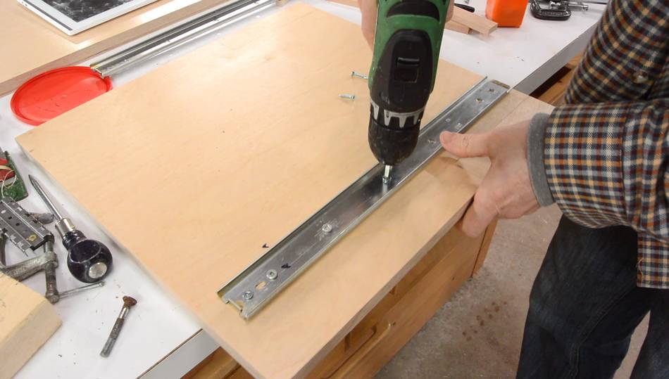 Then screwing it on, using #8 countersink wood screws.
 I made two more spacers to make sure I position the other track parallel
to the first. These were also cut as one spacer, then cut down the middle.
I made two more spacers to make sure I position the other track parallel
to the first. These were also cut as one spacer, then cut down the middle.
 It's very important that the second track is exactly parallel to the first,
so the pilot hole location is very critical. Something like a "vix bit" that
self-centers the pilot holes would be handy, but I don't have one of those.
It's very important that the second track is exactly parallel to the first,
so the pilot hole location is very critical. Something like a "vix bit" that
self-centers the pilot holes would be handy, but I don't have one of those.
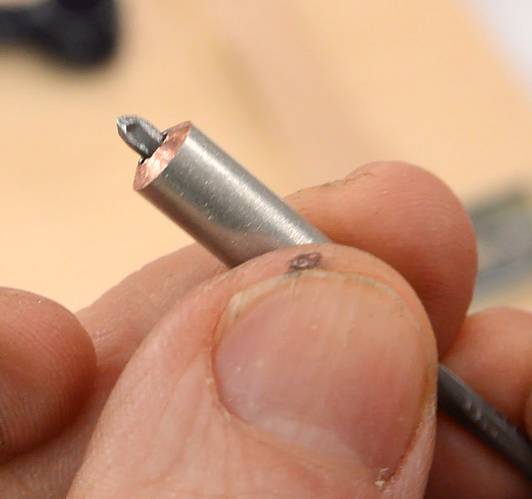
So I rigged up a sort of self-centering center-punch, by grinding a taper onto the end of a spacer on my belt grinder. A belt sander or any sort of grinder would work just as well. I let the spacer spin freely as I ground it to ensure I got a consistent cone shape on it.
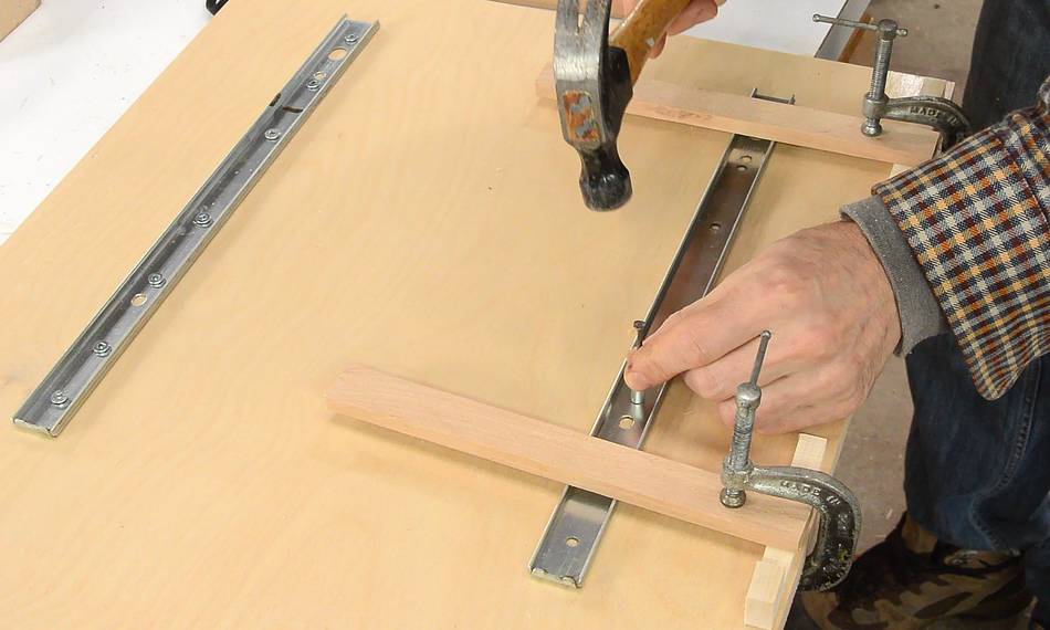
 Then pressing the spacer into the holes and tapping the nail to precisely
center punch the holes.
Then pressing the spacer into the holes and tapping the nail to precisely
center punch the holes.
Also note the two flattened tabs in the track near where I am punching. These also limited the travel of the ball cage. I hammered them flat (using a spacer to avoid hitting the track directly). In the past, I often just ground them flat with an angle grinder.
 Then drilling the pilot holes, then screwing it on (no picture of that).
 Then onto the other half of the tracks. Again, using two spacers that hook
over the edge to position them, then drilling pilot holes and screwing it
on with #8 wood screws.
Then onto the other half of the tracks. Again, using two spacers that hook
over the edge to position them, then drilling pilot holes and screwing it
on with #8 wood screws.
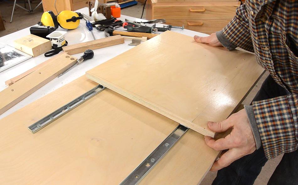
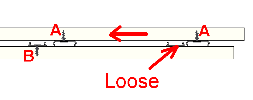 I used the top part with the two outside parts of the slides (A) attached to it
and slide that against the bottom part, which had one slide (B) fixed to it already,
to push the loose slide into the right place. Then carefully sliding it away
(to the right) again and lifting it off, and clamping the loose slide down
without moving it.
I used the top part with the two outside parts of the slides (A) attached to it
and slide that against the bottom part, which had one slide (B) fixed to it already,
to push the loose slide into the right place. Then carefully sliding it away
(to the right) again and lifting it off, and clamping the loose slide down
without moving it.
The main disadvantage of this method is that it's hard to explain. Perhaps the two spacers that engaged on the same side of both tracks, like I used in my previous pantorouter build is better.
 And now mounting the second half of the track.
 The last track needs to be attached with machine screws and washers so that
there is a slight bit of slack for adjustment before the screws are tightened.
The screw holes are slightly larger than the screws.
The last track needs to be attached with machine screws and washers so that
there is a slight bit of slack for adjustment before the screws are tightened.
The screw holes are slightly larger than the screws.
I transferred the location for the counter-bored holes for the washers to the other side by drilling some small pilot holes though the wood. I then used the pilot holes to guide the larger Forstner bit for counterboring the holes for the washers, and after that drilled the screw holes.
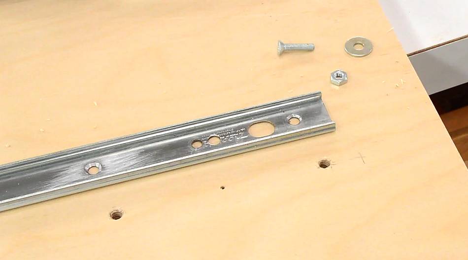 Track, countersink machine screw, washer and nut. The washer and nut fit into
the counterborded hole on the other side.
Track, countersink machine screw, washer and nut. The washer and nut fit into
the counterborded hole on the other side.
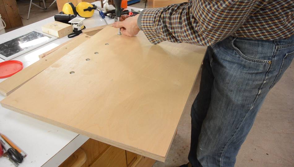
 Screwing it on. The screws are only snugged up slightly so that the track
can still slide side-to-side a little bit.
Screwing it on. The screws are only snugged up slightly so that the track
can still slide side-to-side a little bit.
 Then mating it with the top part (with the ball cages in place). This forces
the track that is mounted with machine screws into alignment.
Then mating it with the top part (with the ball cages in place). This forces
the track that is mounted with machine screws into alignment.
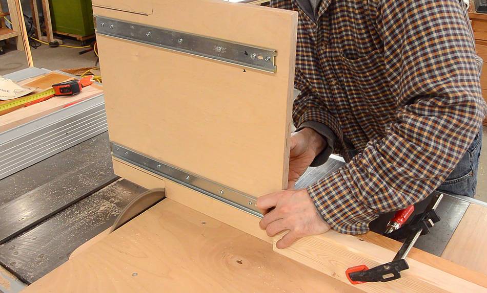
 After making sure the top part can slide back and forth the way it should, I flipped
it over and tightened the nuts for the second track, then checked that it
still slides freely.
After making sure the top part can slide back and forth the way it should, I flipped
it over and tightened the nuts for the second track, then checked that it
still slides freely.
If the tracks on the top part are not exactly parallel, or if the holes for the machine screws are too far off, then tightening the machine screws may cause it to bind.
 After that, I pulled it apart again and cut the notches in the top piece of plywood.
I didn't cut the notches earlier because it was easier to make sure the slides were parallel to the edge without the notches.
 But on sliding things apart, the ball cages came out and the balls fell out.
Drawer slides normally have these tabls (that I flattened to get the ball cages out) to prevent them from coming out. These tabs were in the wrong position. I added a screw to retain the ball cages in the upper half of the tracks. However, the first time I put a screw in, I put it too close to the edge and it hit the inner track. So I had to drill another hole on the opposite side (arrow pointing), and put a screw there, closer to the center. In retrospect, maybe I should have just put a washer under the mounting screw head so that that screw's head comes up further and hits the ball cage.
 The base gets a strip of wood glued to it, about 8 mm from the side of the track.
In the past I put these guards on both sides, but the whole area between the tracks will be closed off, so boards on the inside aren't really necessary.
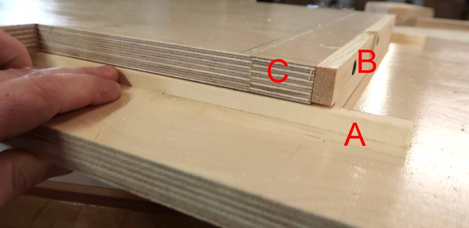 This strip (A) helps keep dust from getting to the slides. I also screwed another
piece onto the end of the top part of the slide to keep dust from getting in there. However,
I ran into a problem where this part hit the ends of the slides on the base, restricting
the range of motion too much. So I extended the top part by gluing a piece on the end.
You won't have to glue a piece onto the end because I adjusted the dimensions in
the plans. However, you should make sure that the inner part of the slide, mounted to
the base, is not longer than 40 cm, or it will interfere with the dust guard (B) when
the slide is slide back.
This strip (A) helps keep dust from getting to the slides. I also screwed another
piece onto the end of the top part of the slide to keep dust from getting in there. However,
I ran into a problem where this part hit the ends of the slides on the base, restricting
the range of motion too much. So I extended the top part by gluing a piece on the end.
You won't have to glue a piece onto the end because I adjusted the dimensions in
the plans. However, you should make sure that the inner part of the slide, mounted to
the base, is not longer than 40 cm, or it will interfere with the dust guard (B) when
the slide is slide back.
Next: Making the pantograph
 Slot mortiser slides (2009)
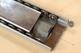 Slides for the pantorouter XL
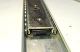 Slides for my first pantorouter