In the process of building my 1"x42" strip sander
and the pantorouter trade show display, I used up
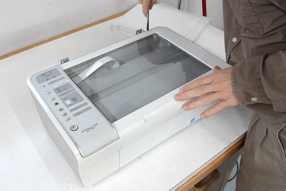
most of the 8 mm shafting I had kicking around. HP ink jet printers like this
all-in-one are a good source, so I took this one apart. I found it on the curb a
year ago, figuring I might still use it if I found a power adapter to go with it.
Every time I take apart an old printer, I'm always amazed at the mechanical ingenuity
inside, so I figured it was worth writing about.
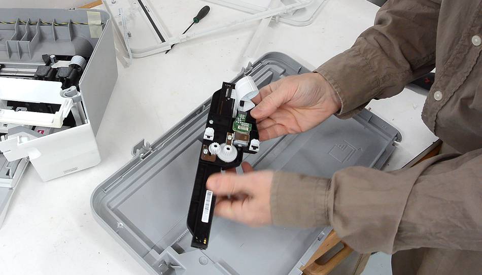
The scanner part sits on top of the printer. Popping it apart,
I'm holding the entire guts of the scanner. It's a multi coloured
LED light strip, a sensor strip, and a small DC motor with some gearing on it to drive
it along a rack gear on the bottom of the scanner enclosure. Scanners used to
be much more complicated affairs, with stepper motors, fancy optics with mirrors,
and polished shafts for gliding along.
It's no wonder that scanners have become so cheap.
Last time I wanted to buy a printer I bought a printer/scanner, because that was
the cheapest option!
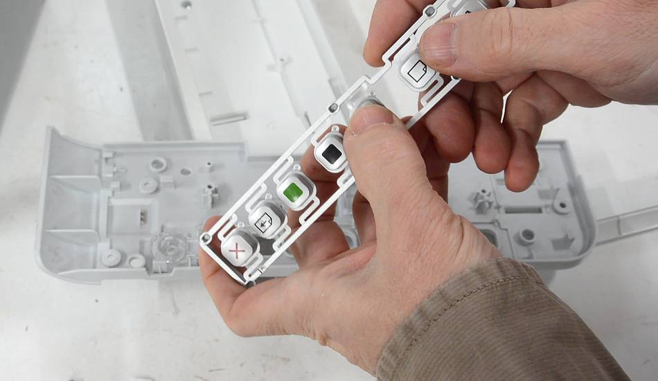
The buttons on the top have no explicit springs, just bits of plastic that bend as
they are pushed.
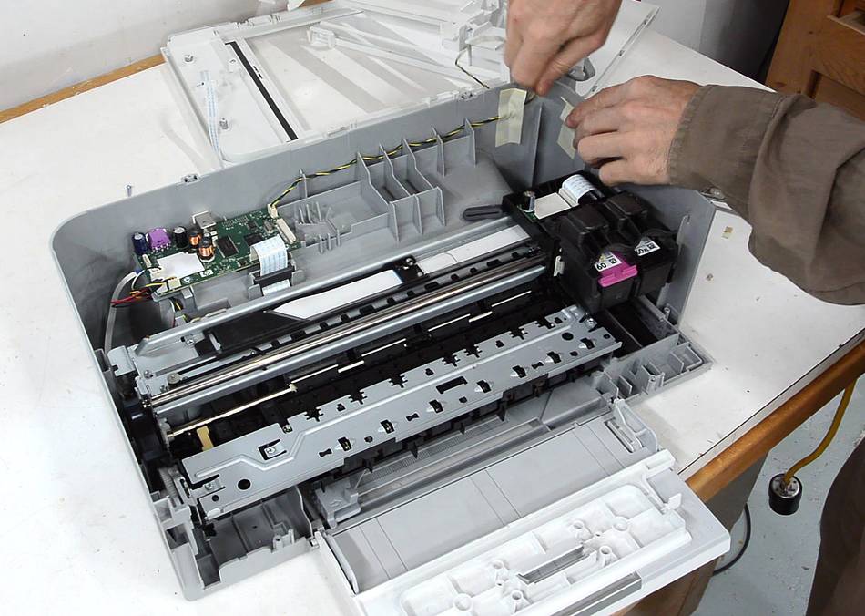
The plastic enclosure forms a tub around the printer mechanism.
The electronics is just a small board in the corner.
No visible power transistors or power ICs. I think the small DC motors
this printer uses are more efficient than the stepper motors printers used
to use, so less need for power electronics.
I cut the plastic tub off with a bandsaw to make it easier to look
at the mechanism.
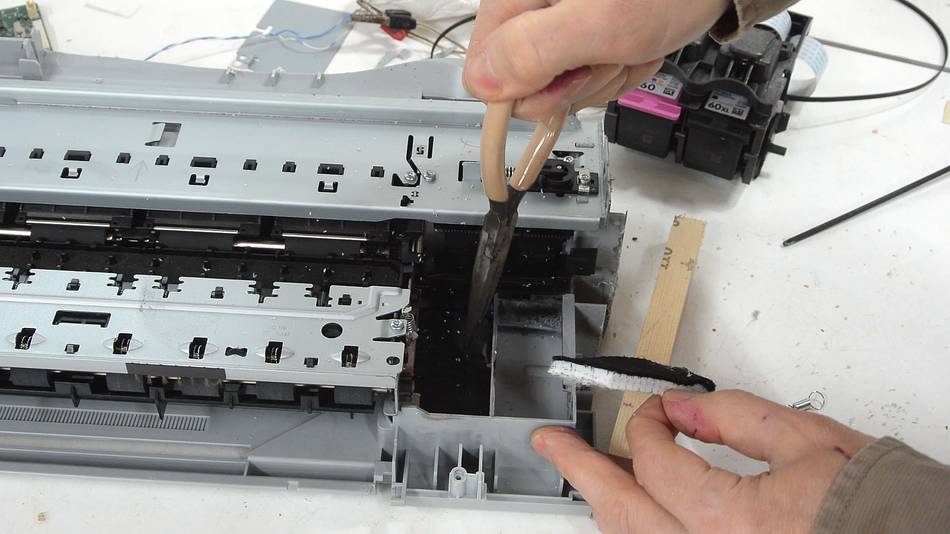
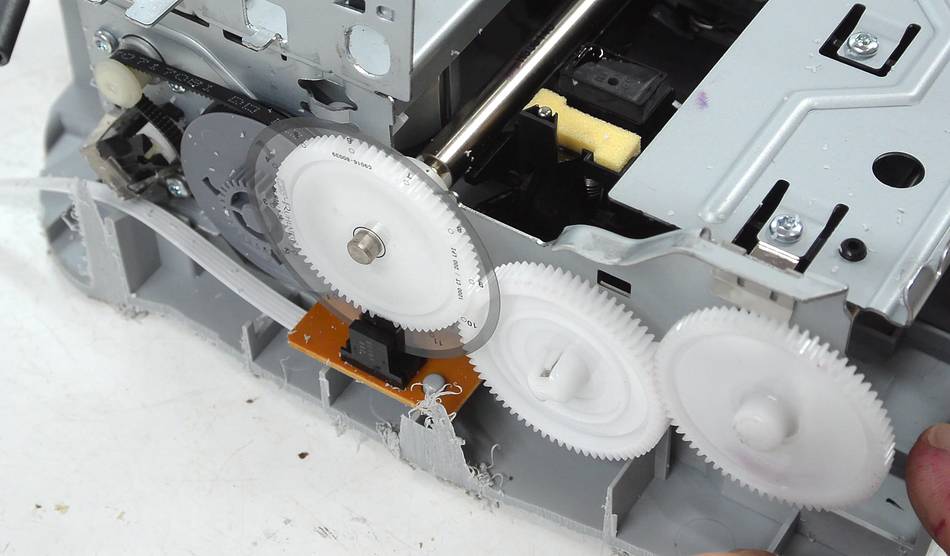
Here you can see the polished 8 mm shaft that the print head slides along, the
timing belt that drives it (my finger is pushing on it), and
a transparent plastic ribbon with very fine black bars on it for position
sensing.
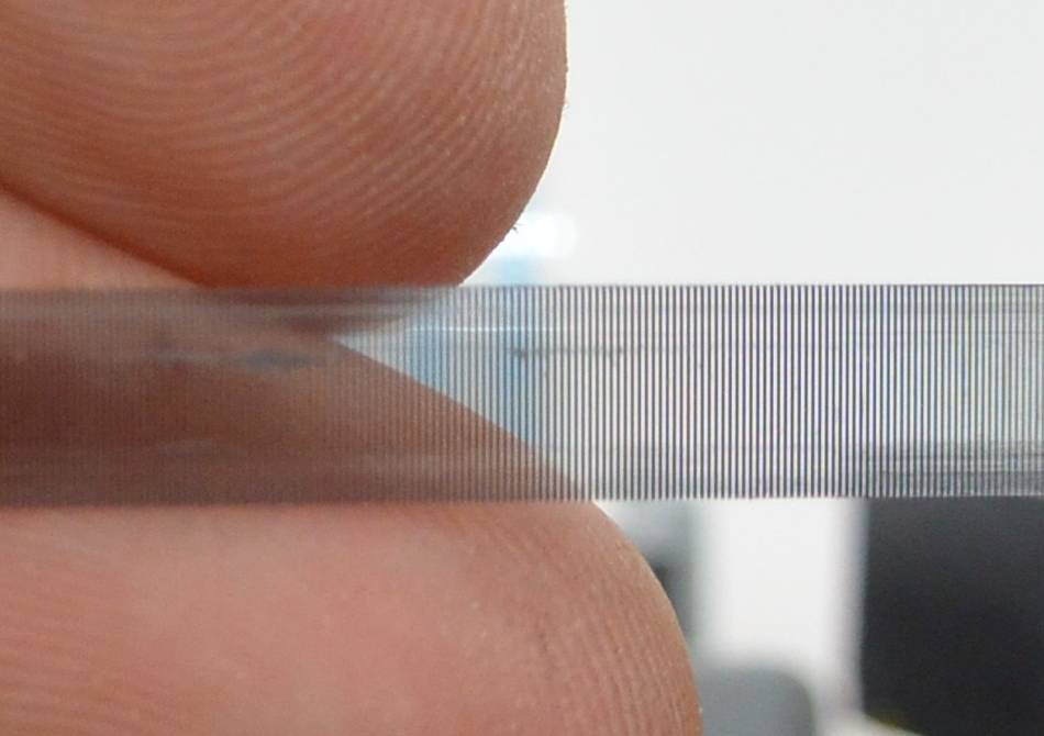
A close up of the plastic strip with the fine black bars, about
six per millimeter. The strip
is stretched taut across the travel of the print head. An optical
sensor on the print head reads the strip. Using quadrature encoding,
the printer knows exactly how far and which direction the
print head has moved.
This allows the printer to establish the print head position with very
high repeatability, more precisely than using a stepper motor and timing
belt. This is necessary for high resolution bidirectional
printing.
The motor driving the print head is just a small
DC motor. DC motors are faster and more efficient,
but positional feedback is needed to achieve precise control. But
position feedback is already necessary for the print head, so might
as well use it to control the DC motor too.
8 mm polished steel rod extracted. The print head slides along this
rod. This is the main "goodie" that I was after.
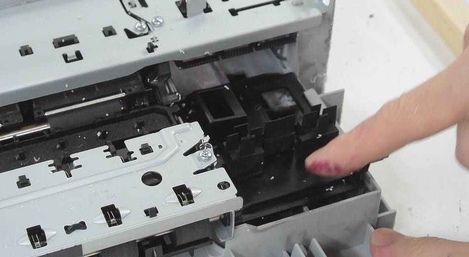
On the right end of the printer is the spittoon.
The printer moves the print head over this side and fires the jets at full
power to clean them out. Felt pads in the bottom capture the ink.
There is also a squeegee arrangement that can move across the print heads
to help clean them.
On the left side of the printer are two rubber pads that move up when the
print head pushes against a pin. These pads cap the printer
cartridges when the print head is parked to keep them from drying
out.
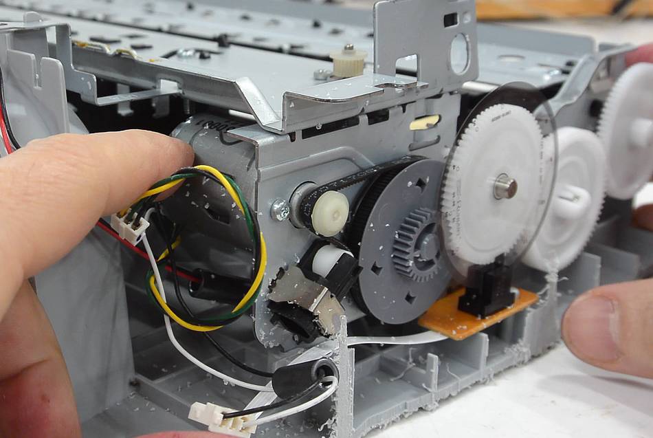
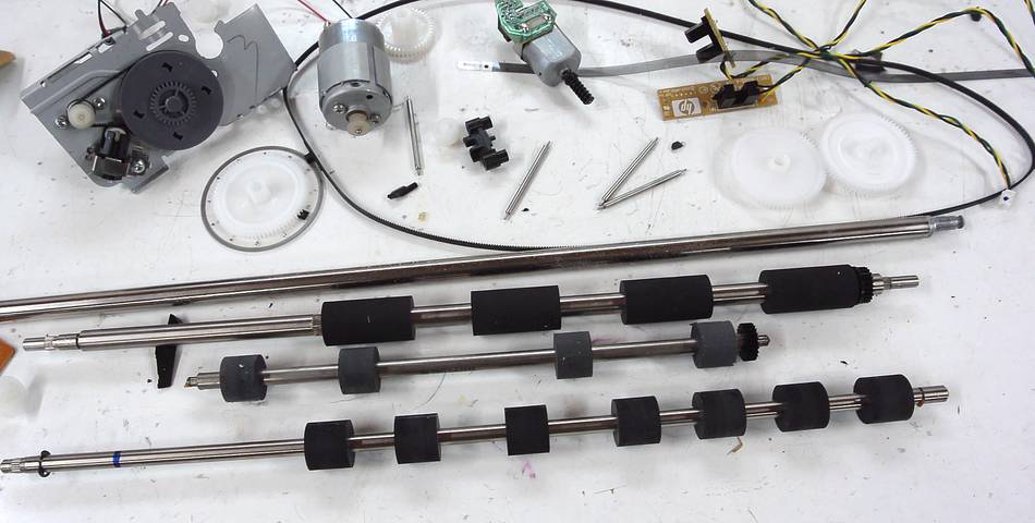
At left, the motor and gearing for the paper advance mechanism.
The left-most white gear in the photo has a transparent disk with a very
fine set of lines around it. An optical encoder (on the brown circuit
board below) detects precise movement of the paper advance,
similar to how the print head position is detected.
The motor for the paper advance is also a small DC motor.
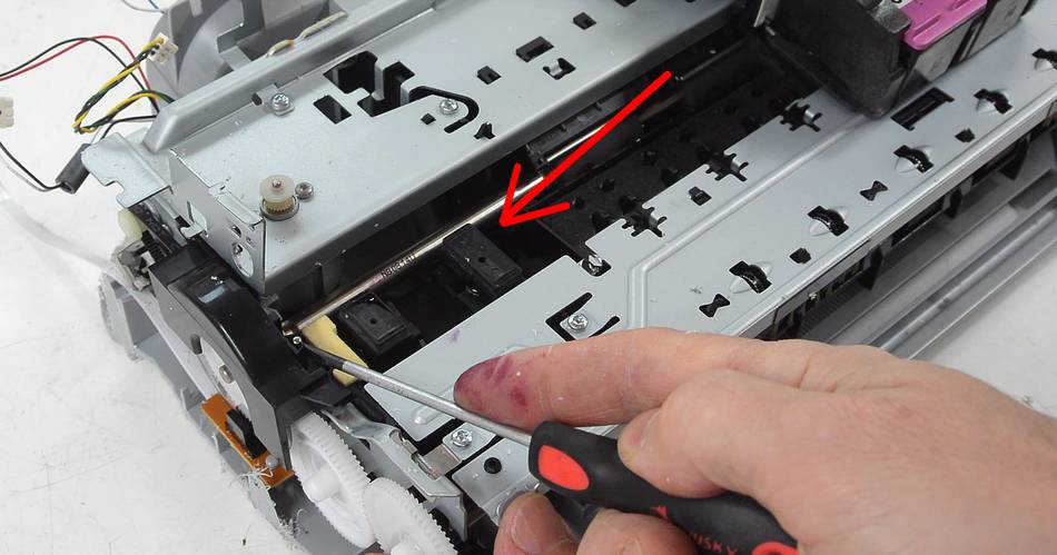
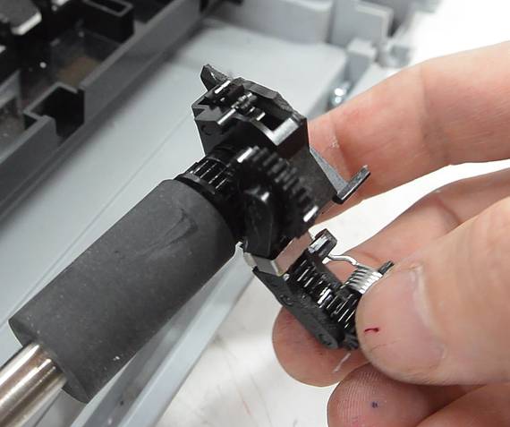
I had been puzzling over what activates the squeegee mechanism on the right. I discovered
how it worked after I broke it. There is a small gear (A) that activates the squeegee,
and this is pulled up by a piece of plastic (B) which I broke. This plastic was
part of the assembly at the end of the feed roller. When the print head moves all the
way to the right, it turns this mechanism, which causes part B to pull up gear A
to engage it with the gear on the feed roller. So the paper advance motor powers
the squeegees. This means the squeegee can only be used between sheets of paper.
The paper feed mechanism has a lot of gears, and these, I think, engaged by running the
paper feed motor backwards.
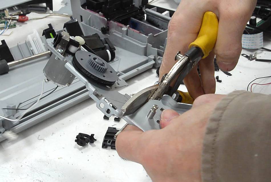
I left the paper feed motor, belt, and pulley attached to their piece of chassis and
cut that off with tin snips. Might be useful for something some day.
Here are the pieces I kept. The main paper feed is also on an 8 mm shaft (bonus),
while the other rollers are on 6 mm shafts. I used up most of my 6 mm shafting when
I made lots of followers for my pantorouter,
so it was nice to replenish that stock too.
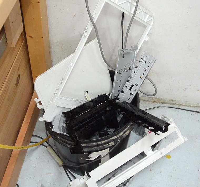
And here's the junk I didn't keep. Kind of wasteful, but the whole printer came from
the garbage, so my salvaging was still a net garbage reduction.
 In the process of building my 1"x42" strip sander
and the pantorouter trade show display, I used up
most of the 8 mm shafting I had kicking around. HP ink jet printers like this
all-in-one are a good source, so I took this one apart. I found it on the curb a
year ago, figuring I might still use it if I found a power adapter to go with it.
In the process of building my 1"x42" strip sander
and the pantorouter trade show display, I used up
most of the 8 mm shafting I had kicking around. HP ink jet printers like this
all-in-one are a good source, so I took this one apart. I found it on the curb a
year ago, figuring I might still use it if I found a power adapter to go with it.


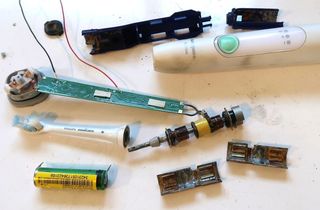 What's inside a Sonicare toothbrush
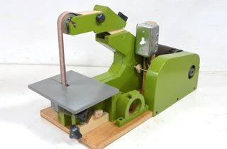 Strip sander
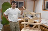 Pantorouter trade show display
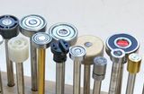 Making pantorouter followers
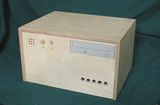 Wooden computer case
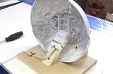 Wifi antenna
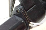 Repairing plastic parts
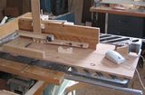 Computer controlled
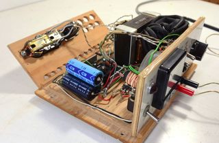 Homemade bench top
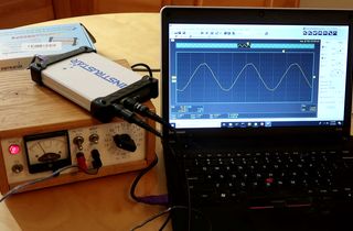 Reviewing the cheapest USB scope I could find online
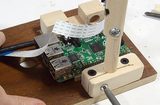 Raspberry Pi
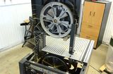 Bandsaw repair fail
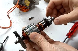 Oiling a noisy shopvac
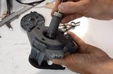 Wet rotor dishwasher motor