 I want both wheels to be up against the frame, but the lower wheel will
have the drive pulley behind it, so I need to make a cavity in the frame
for that to fit into.
I want both wheels to be up against the frame, but the lower wheel will
have the drive pulley behind it, so I need to make a cavity in the frame
for that to fit into.
I want both wheels to be up against the frame, but the lower wheel will
have the drive pulley behind it, so I need to make a cavity in the frame
for that to fit into.
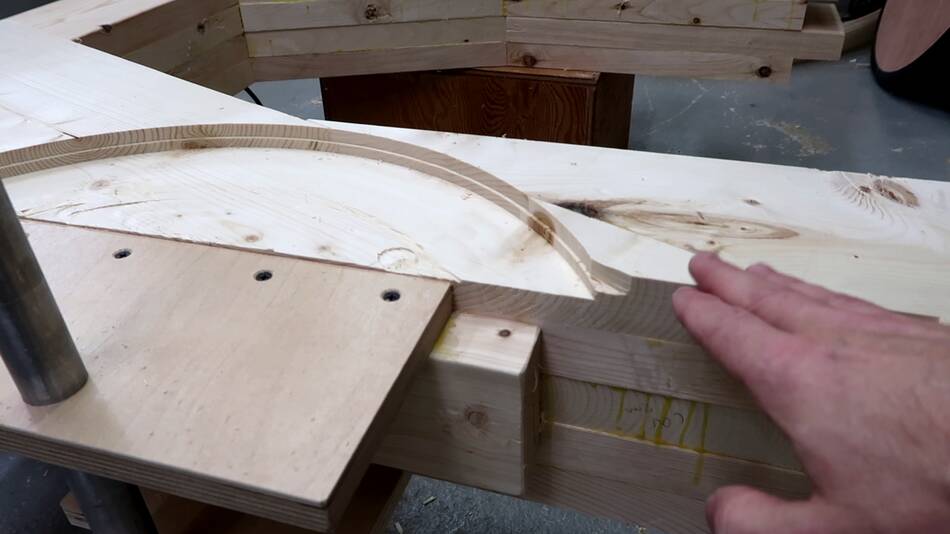
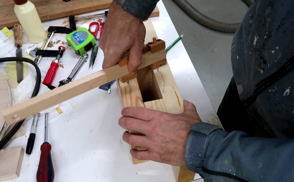
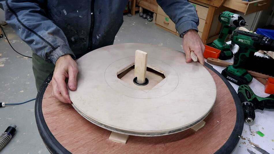
I made a piece of wood to fit in the middle of my big pulley so I could hold it against the frame and mark how much of a cut-out I had to make for it.
In retrospect, I should have made that drive pulley a bit smaller so I wouldn't have to cut so much of the frame.
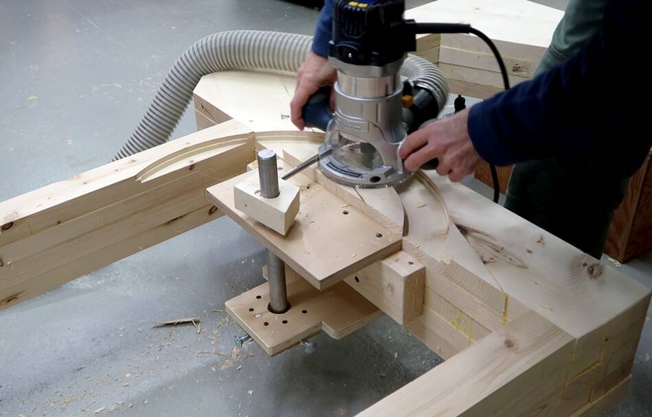 I rigged up a simple sort of circle jig to route out that cavity....
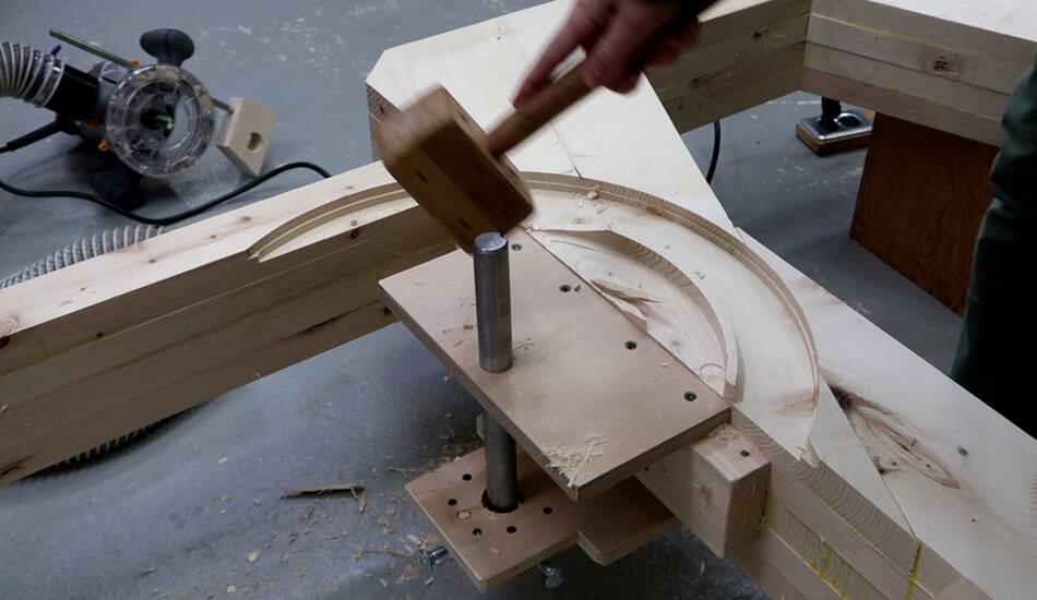 ... leaving some ridges so the router's base would have something to ride
on to control the depth of cut. I removed those with hammer and chisel.
... leaving some ridges so the router's base would have something to ride
on to control the depth of cut. I removed those with hammer and chisel.
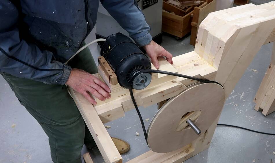
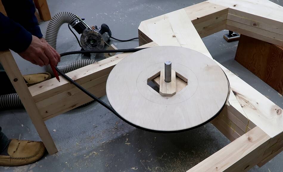 Then placing the pulley to figure out where the belt needs to go.
 I need to cut out some clearance for that belt as well.
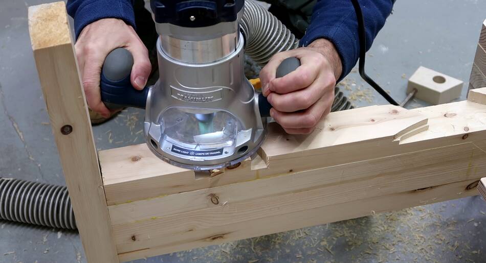
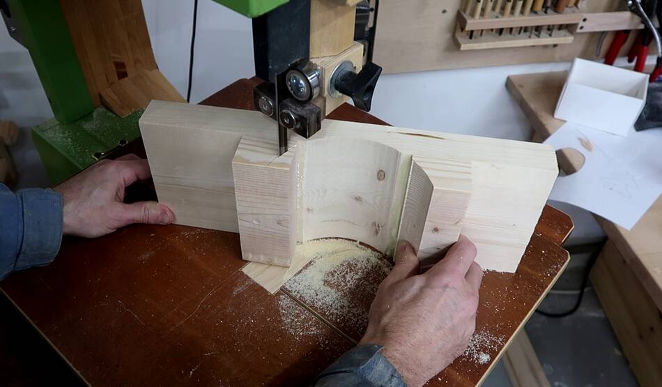
 On previous bandsaws, I just used one less layer on the bottom front to
leave room for the drive pulley, but with 34 mm thick layers on this
one, it made more sense to cut away half a layer instead of
leaving off a whole layer.
On previous bandsaws, I just used one less layer on the bottom front to
leave room for the drive pulley, but with 34 mm thick layers on this
one, it made more sense to cut away half a layer instead of
leaving off a whole layer.
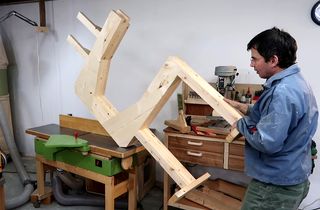
I could have moved the top and bottom wheels forward a bit to have room behind both wheels, but the further the wheels are from the frame, the more twisting force the wheels apply to the frame, which causes more distortion, and also more bending moment on the top wheel mount. So after giving this a lot of thought, I decided that routing out part of the frame was the best way forward, even though it looks like a mistake.
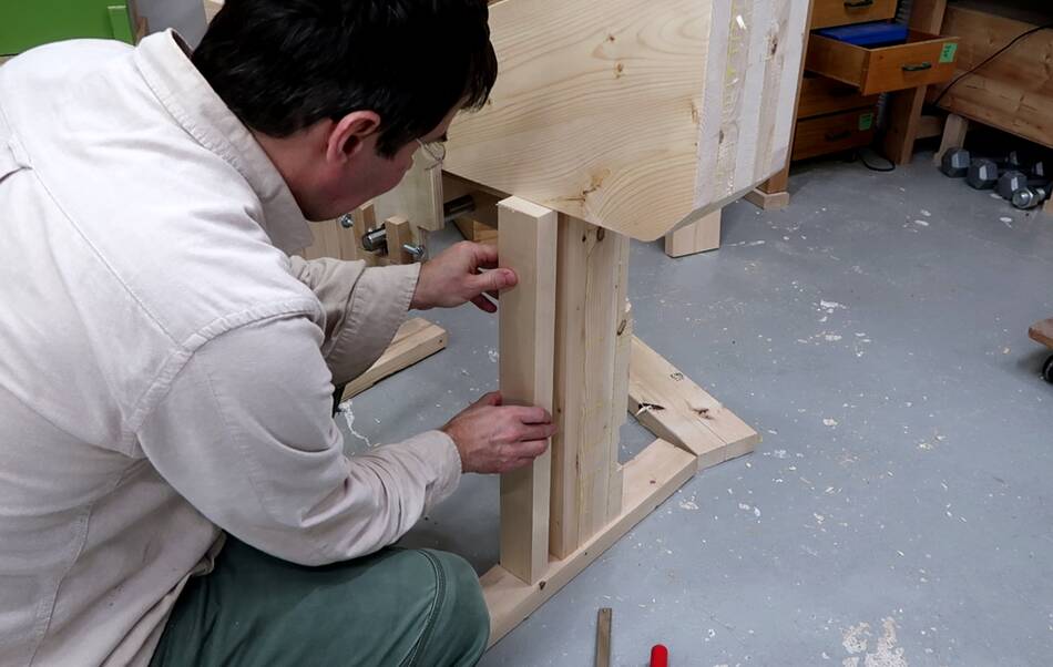 Adding an extra layer to the back of the leg to get more surface to mount
the motor to.
Adding an extra layer to the back of the leg to get more surface to mount
the motor to.
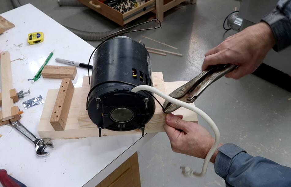
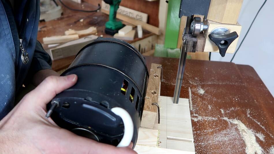
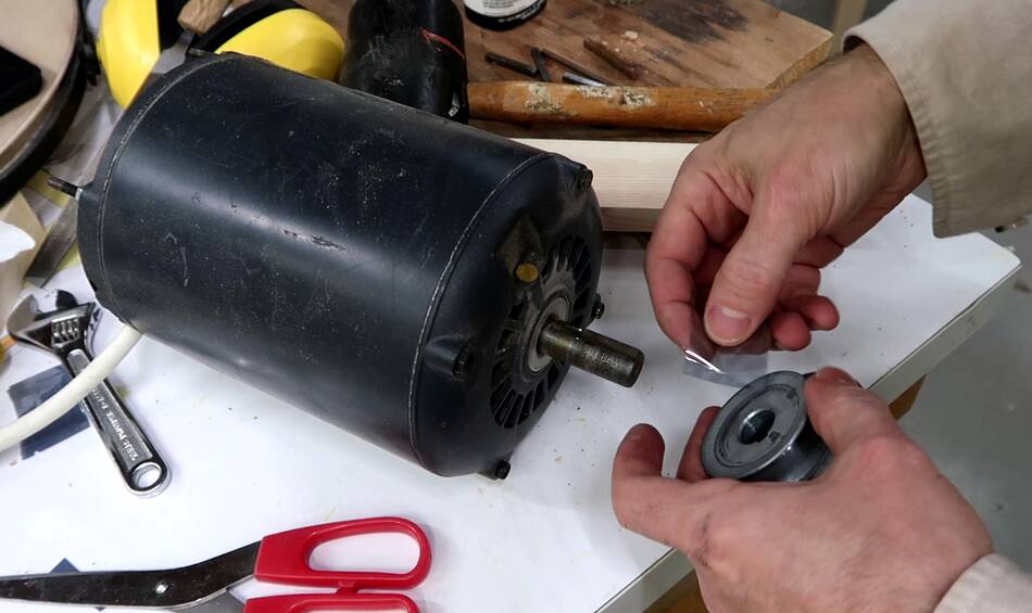 I'm using this old 2/3 hp motor that
came from this crummy bandsaw that wasn't worth fixing.
I'm using this old 2/3 hp motor that
came from this crummy bandsaw that wasn't worth fixing.
I'm using a piece of anti-static bag as a shim to make sure the pulley will have a tight fit on the shaft. These set screws on the pulleys can't be counted on to not come loose over time. In fact, that bandsaw that this motor came from became unusable because the set screws weren't enough to hold them tight, and the hole in the pulley had worn so large from this that it was no longer usable.
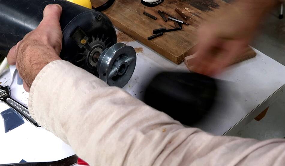 But maybe I used too much shim. It was very difficult to get that pulley
on. On the plus side, it will probably never come loose.
But maybe I used too much shim. It was very difficult to get that pulley
on. On the plus side, it will probably never come loose.
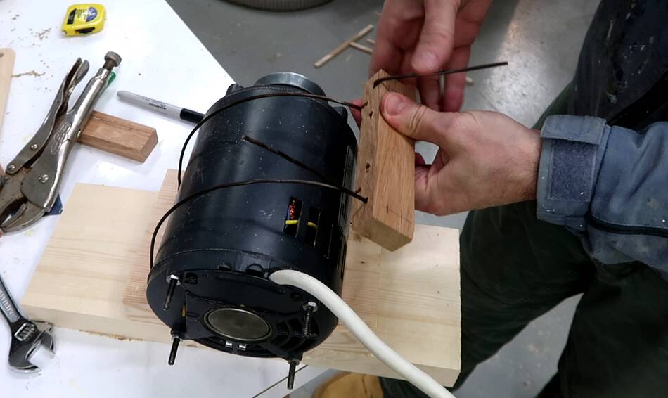
 Then untwisting a wire coat hanger for mounting hardware.
To the right, you can see the mounting bracket being glued up.
 I then marked the radius of the motor on the bracket...
 ... and cut it out on one of my other bandsaws.
 I bent the coat hanger wire into the shape of a large staple, then inserted
it through two holes in my mounting bracket.
I bent the coat hanger wire into the shape of a large staple, then inserted
it through two holes in my mounting bracket.
 I then bent the wire around the motor and bent two hooks onto the end of it.
 These hooks fit around a block to pull on the wires. I wanted those hooks
to go through two holes in the block, but forgot to put the wires
thru the holes of the block before bending the hook.
Rather than straightening and then re-bending the wire, I cut two of the
jholes into slots so I could still get the block onto the wires.
Then bending over the ends of the wire again.
These hooks fit around a block to pull on the wires. I wanted those hooks
to go through two holes in the block, but forgot to put the wires
thru the holes of the block before bending the hook.
Rather than straightening and then re-bending the wire, I cut two of the
jholes into slots so I could still get the block onto the wires.
Then bending over the ends of the wire again.
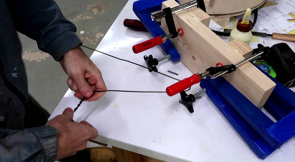
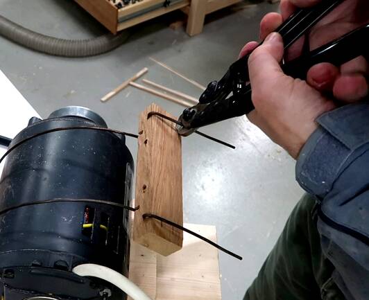
I used a bicycle brake cable cutter to cut off the coat hanger wire. I much prefer this cutter to bolt cutters for cutting wire coat hangers.
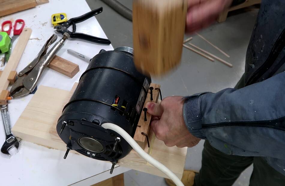
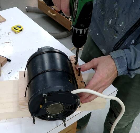 I then put screws in the screw holes, hit them with a hammer to mark the pilot
hole location, then drilled pilot holes, then screwed
the block down, so that the coat hanger wires pull tight around the motor.
I then put screws in the screw holes, hit them with a hammer to mark the pilot
hole location, then drilled pilot holes, then screwed
the block down, so that the coat hanger wires pull tight around the motor.
 Checking the motor mount on the bandsaw frame.
 I still needed to cut some slots in the motor mount so that I can screw it
to the frame later. But I'll hold off screwing it on until other stuff
is more finalized.
I still needed to cut some slots in the motor mount so that I can screw it
to the frame later. But I'll hold off screwing it on until other stuff
is more finalized.
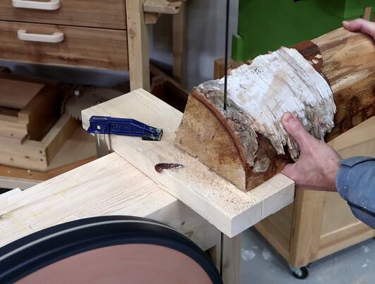
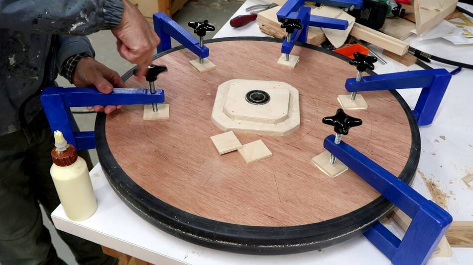 I wanted the pulley to be offset about 9 mm from the lower wheel. So I glued
some small pieces of plywood right over where the internal spokes are in
the wheels.
I wanted the pulley to be offset about 9 mm from the lower wheel. So I glued
some small pieces of plywood right over where the internal spokes are in
the wheels.
 But the wheel flange is a bit thicker than the plywood spacers, so I had to
route out a few millimeters from the pulley to make it fit.
But the wheel flange is a bit thicker than the plywood spacers, so I had to
route out a few millimeters from the pulley to make it fit.
 Then placing the pulley on the wheel...
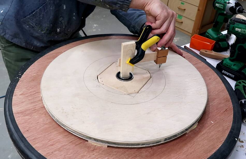
 ... and clamping part of my beam compass to a piece of wood stuck in the bearing
to check that the circle on the wheel is perfectly centered with the bearing.
... and clamping part of my beam compass to a piece of wood stuck in the bearing
to check that the circle on the wheel is perfectly centered with the bearing.
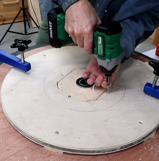
Once I was satisfied it was centered, I screwed it on with 12 #8 screws. The pulley doesn't get that much force on it, but the belt pulls it back and forth all the time. More screws ensure that it doesn't get wiggled loose over time.
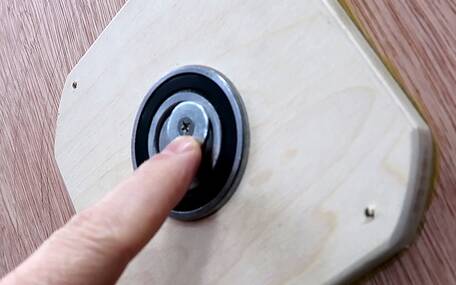
 I placed the wheel backwards on the frame and spun it by hand to make sure
the pulley didn't wobble.
I placed the wheel backwards on the frame and spun it by hand to make sure
the pulley didn't wobble.
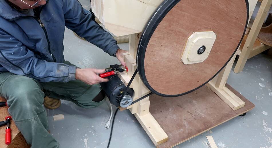 Then placing it the right way around and clamping the motor to the frame.
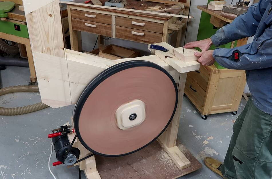
 Then spinning it up, and cutting some wood.
I have no blade guides yet, but the slot in the piece of wood that I use as
a temporary table helps guide the blade on the bottom.
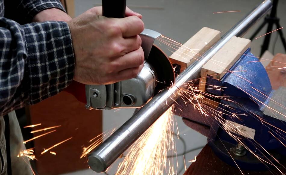 I had also cut the axles to their final length with an angle grinder.
I used a sharpie to mark my cut all the way around to make sure I'd get it square, then cut from one side, turned the shaft 90 degrees, kept cutting, turned it again, and finished the cut.
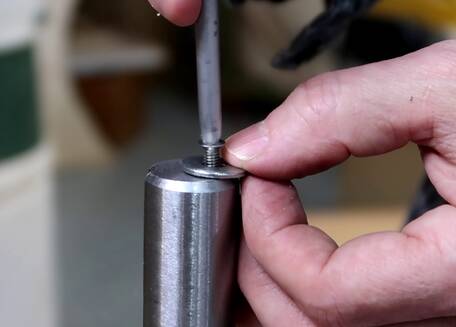

 I then drilled a hole in the end of the shaft, off center,
tapped it for a small screw, and washer. I had difficulty
finding a washer large enough but with a small enoguh hole
last time. This time I drilled the hole off-center, so
a smaller washer is enough to keep the wheels from sliding
off the axles.
I then drilled a hole in the end of the shaft, off center,
tapped it for a small screw, and washer. I had difficulty
finding a washer large enough but with a small enoguh hole
last time. This time I drilled the hole off-center, so
a smaller washer is enough to keep the wheels from sliding
off the axles.
Next: Blade guides (not yet built)
 Making the frame
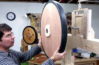 Wheel mounts for my 26" bandsaw
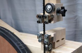 Blade guides for my 26" bandsaw
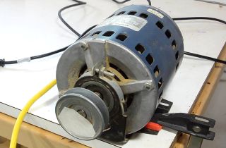 How induction motors work
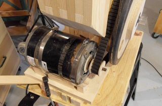 Motorizing my 14" bandsaw