 The jig consists of a sort of table saw sled, which has a metal bar mounted to the
bottom of it for sliding in the table saw's slot.
The jig consists of a sort of table saw sled, which has a metal bar mounted to the
bottom of it for sliding in the table saw's slot.
See also: Improved version 2 of this jig
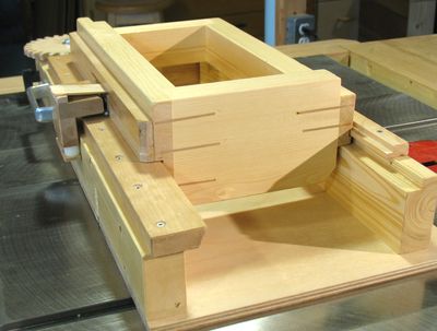
I built my new screw advance box joint jig to allow very precise cutting of box joints in a whole stack of work pieces at once. Rather than the traditional method of doing box joints, which involves indexing each finger off of the previous finger, this jig uses a screw to give absolute position to each finger in the joint.
I had previously explored the idea of using a screw advance for box joints with my box joint jig and with my computerized table saw jig
The jig consists of a sort of table saw sled, which has a metal bar mounted to the
bottom of it for sliding in the table saw's slot.
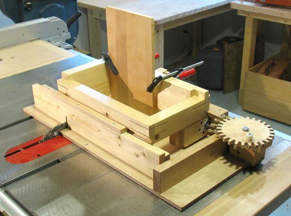
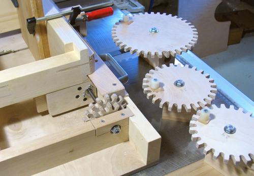
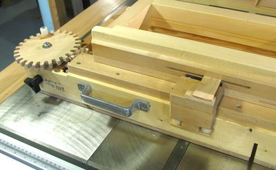
The base has two rails that go side to side, on which the carriage that holds the work piece can slide. Sideways movement of the carriage holding the work pieces is controlled by a threaded rod, which is turned by a crank via a set of wooden gears.
Different primary gears (the gear with the crank on it) can be swapped onto the jig, so that different finger spacings can be achieved without having to resort to making partial turns for each finger advance. Each advance may thus involve two whole turns, for example, and always stops with the crank handle in the same position.
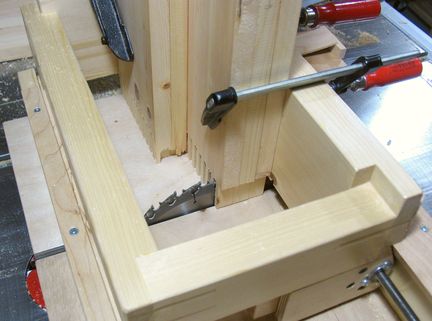
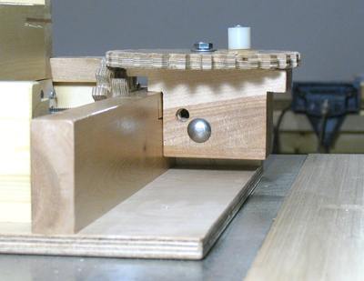
 The carriage slides on a sort of half-dovetail, which is on the operator side of the jig.
On the other side, it just slides on a simple square slot.
A spring loaded roller keeps the carriage pushed into the wedge of the
half dovetail, so that the position of the carriage on the sled is consistent and precise.
The carriage slides on a sort of half-dovetail, which is on the operator side of the jig.
On the other side, it just slides on a simple square slot.
A spring loaded roller keeps the carriage pushed into the wedge of the
half dovetail, so that the position of the carriage on the sled is consistent and precise.
The slot that is used on the other side of the carriage is actually relatively loose. Really, the carriage is pushed down against the support at all time, and the slot is just there so that the carriage doesn't pop off the base sled when I pick up the jig by the carriage.
 The carriage has an opening that is 30 cm by 15 cm for the work piece.
This allows for multiple boards, up to 30 cm in width to be cut all at once. Realistically,
some of the 15 cm space will always be taken up by a "sacrificial board", to prevent tearout
on the end, and by the clamps to hold the boards. So I wouldn't cut
a stack of boards that total more than 10 cm in thickness at one time.
The carriage has an opening that is 30 cm by 15 cm for the work piece.
This allows for multiple boards, up to 30 cm in width to be cut all at once. Realistically,
some of the 15 cm space will always be taken up by a "sacrificial board", to prevent tearout
on the end, and by the clamps to hold the boards. So I wouldn't cut
a stack of boards that total more than 10 cm in thickness at one time.
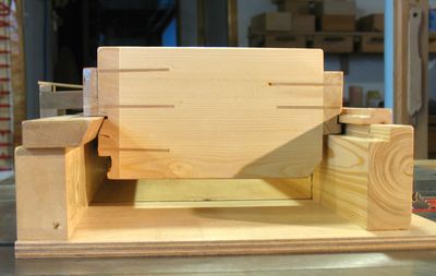
In this photo I was cutting the box joints for some drawers, some of which are 21 cm deep, the others 12 cm deep. So there are two narrower pieces in the jig along with two wider pieces, plus a fifth sacrificial board to prevent tearout.
 To allow for different amounts of advance per turn, different set of primary gears can
be swapped into the jig. There are also two sizes of gear on the
screw shaft, one has 12 teeth, and the other has 16 teeth. That way, I have more combinations
that I can use to get different spacings.
To allow for different amounts of advance per turn, different set of primary gears can
be swapped into the jig. There are also two sizes of gear on the
screw shaft, one has 12 teeth, and the other has 16 teeth. That way, I have more combinations
that I can use to get different spacings.
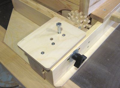
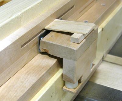
When I first used the jig, I just clamped he block with the primary gear in place with a clamp, but later I decided to use a screw to hold the blocks in place.
 The image at left shows the gear block, mounted in place with a carriage bolt.
If you mouse over the image, it shows the gear block in the lower position.
The gear block is shaped such that it fits nicely in two positions.
The image at left shows the gear block, mounted in place with a carriage bolt.
If you mouse over the image, it shows the gear block in the lower position.
The gear block is shaped such that it fits nicely in two positions.
<--- Mouse over image to animate
So far I have made five primary gears, with 20, 24, 26, 35, 39, 42, 47 teeth. There is no system whatsoever in these sizes. Whenever I need a particular spacing, and I don't already have a gear of the right size, I just make another one. The 39 tooth primary against the 12 tooth secondary, for example, results in a 5.12 mm advance per turn, which is perfect for making very fine box joints or finger joints with my regular thin kerf saw blade. Three turns of the 42 tooth gear against the 16 tooth gear is just the right amount of advance for making box joints with the two saw blades of my dado set, without any spacers and chip removers in it.
 I ended up making a lot of primary gears for my jig and eventually came up with a better method
of mounting the gears for my
improved version 2 of the jig
The bolt to hold the gear gets locked
in place as the block locking knob is tightened, so gear changes are fairly fast, and there is no need
to make a separate gear mount for each primary gear.
I ended up making a lot of primary gears for my jig and eventually came up with a better method
of mounting the gears for my
improved version 2 of the jig
The bolt to hold the gear gets locked
in place as the block locking knob is tightened, so gear changes are fairly fast, and there is no need
to make a separate gear mount for each primary gear.
 To get different spacings, I can pick one of a number of primary gears, and mesh that with
the 12 tooth or the 16 tooth secondary gear, and decide how many turns to turn per advance.
If I want a particular advance per cut, it makes it difficult to figure out which combination
of primary, secondary, and turns per cut gets me closest among the gear sets I already have.
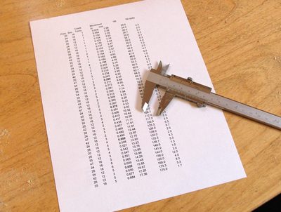
So I worked out all the combinations of primary gear, secondary gear and turns on the crank.
I worked out the advance for each combination, and made a sorted list of these.
Now, if I want a certain spacing, I can just look up on the spreadsheet to see how close I can get to
that spacing with the gears I already have before deciding whether to make another gear.
To get different spacings, I can pick one of a number of primary gears, and mesh that with
the 12 tooth or the 16 tooth secondary gear, and decide how many turns to turn per advance.
If I want a particular advance per cut, it makes it difficult to figure out which combination
of primary, secondary, and turns per cut gets me closest among the gear sets I already have.
So I worked out all the combinations of primary gear, secondary gear and turns on the crank.
I worked out the advance for each combination, and made a sorted list of these.
Now, if I want a certain spacing, I can just look up on the spreadsheet to see how close I can get to
that spacing with the gears I already have before deciding whether to make another gear.
I wrote a program that allows you to enter which gears you have made and automatically generate a custom table based on your gears. It runs in the web browser on any computer (mac or PC), no 'install' necessary, and it's included if you buy the plans for the improved version 2 of this jig
 Alignment of the jig works by continuously pressing the carriage part against the half dovetail
on the operator side of the jig. This is done with a set of pinch rollers, which always
pull the carriage towards the operator side and into the half dovetail rail on that side.
Alignment of the jig works by continuously pressing the carriage part against the half dovetail
on the operator side of the jig. This is done with a set of pinch rollers, which always
pull the carriage towards the operator side and into the half dovetail rail on that side.
I couldn't find a suitable spring for spring loading the rollers, so I just used a thin piece of wood, with a block under it. I'm sure the thin piece of wood will eventually need replacing, but it's just a thin piece of maple, so that's no worry.
 I mounted a big drawer handle to the operator side of the jig.
The first time I used it, I realized I didn't have a good place to grab the jig to
pull it back after making a cut.
The handle in that position is a good place to grab, and it's far enough from where
the blade goes through the jig to be safe.
I mounted a big drawer handle to the operator side of the jig.
The first time I used it, I realized I didn't have a good place to grab the jig to
pull it back after making a cut.
The handle in that position is a good place to grab, and it's far enough from where
the blade goes through the jig to be safe.
In terms of safety, this jig is much safer than the typical way of cutting finger joints. The drawer handle, and the crank on the gear are about as close as one gets to the blade when cutting a set of fingers.
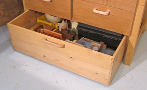
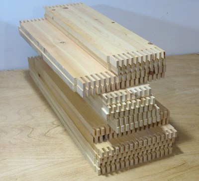 One of the first projects I built using this jig is some drawers for one of my workbenches.
I made four drawers, and joined all the corners with box joints, which made for
quite a lot of fingers to be cut. Most of these
I cut with a stack of four boards in the jig at one time. The fourth photo in this article
is actually of these boards being cut.
One of the first projects I built using this jig is some drawers for one of my workbenches.
I made four drawers, and joined all the corners with box joints, which made for
quite a lot of fingers to be cut. Most of these
I cut with a stack of four boards in the jig at one time. The fourth photo in this article
is actually of these boards being cut.
You may notice that the boards on top have the box joints cut quite deeply. They are the drawer fronts, using my super storng joints for drawers
 The video is of me cutting the boards for this drawer on the jig. The boards are
the maximum width that the jig can hold, and the maximum length I can put into it without
hitting the ceiling in my workshop.
The video is of me cutting the boards for this drawer on the jig. The boards are
the maximum width that the jig can hold, and the maximum length I can put into it without
hitting the ceiling in my workshop.
Version 2 (Improved version) of this jig