
It always bothered me about my original
finger jointing jig
that I had limited choice in the spacing of the fingers.
In order to keep the jig simple to
operate, the teeth need to be spaced an integer number of turns of the
screw. In terms of stacking saw blades and shims, that works out
to just two choices: 4 turns per cut, or 6 turns per cut.
If the hand crank is replaced with a stepper motor, the
advance between cuts can be any interval.
Of course, controlling a stepper motor requires a bit of electronics,
so that's where I started this project.
|
|
Going through my junk bin, I found a circuit board with 11 power transistors on it that suspiciously looked like it might have been used to control a stepper motor or something like that at some point. Working out the schematic from the traces, it was almost what I needed for my purposes. I cut out the part of the circuit board with the transistors and a few logic chips with a Dremel tool, changed the wiring of the diodes on the board to act as catch diodes, and soldered a printer cable to drive the logic side. Then I started playing around with hooking up stepper motors to that board. It worked quite well, and with all the experiments I did, I didn't burn out any of the transistors, so I figured they were up to the job. I then mounted the board in its own box, along with a power supply from god knows where, and two 100 watt bulbs as series (current limiting) resistors for the stepper motors. The board has enough circuitry on it to control a second stepper motor, but I didn't install the resistors for that one. This was long before stepper drivers could be ordered cheaply online.

|
Left: Laptop computer in protective case
|
The jig itself took some trial and error to come up with. Originally, I built it with a threaded rod as the lead screw, with a ball bearing on either end, and a nut running along the middle to move part of the jig. The shaft was turned thru a couple of gears from the stepper motor, gearing up the motor by about a factor of two. I figured I would be able to turn the shaft faster that way.
 This didn't work very well at all. My
alignment wasn't that good, and the threaded rod wasn't that straight.
With the nut held rigidly to the sliding part of the jig, and the threaded rod
held on either end, the misalignment would cause a lot of friction. I
needed a lot more torque than the motor could put out, never mind that I had geared it up.
Also, the gearing backlash caused a bit of
vibration at startup, which could cause the stepper motor to be knocked
out of sync. I also
realized that I have never seen a machine that actually geared a stepper
motor up, only down. I suspect gearing up a stepper just isn't
such a good idea.
This didn't work very well at all. My
alignment wasn't that good, and the threaded rod wasn't that straight.
With the nut held rigidly to the sliding part of the jig, and the threaded rod
held on either end, the misalignment would cause a lot of friction. I
needed a lot more torque than the motor could put out, never mind that I had geared it up.
Also, the gearing backlash caused a bit of
vibration at startup, which could cause the stepper motor to be knocked
out of sync. I also
realized that I have never seen a machine that actually geared a stepper
motor up, only down. I suspect gearing up a stepper just isn't
such a good idea.
So I got rid of my gearing, and the ball bearings. Instead, I
coupled the threaded rod straight to the stepper motor shaft using
plastic rubber hose. The rod itself was now supported only by the
stepper motor and the nut. Because these are relatively far
apart, the mechanism is much more tolerant of misalignment.
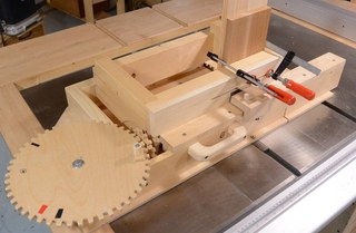
In the above image, I had already ripped off my gears and bearings, and was
about to mount the stepper motor (center left) to the end of the shaft (bottom
right). The push/pull thrust is
all taken up by the stepper motor, whose bearings seem capable of
supporting it.
In the slot (center, towards top), you can see a block of wood. This
block has the nut attached to it, which gets screwed in and out as the
threaded rod turns.
A board slides in front of the slot, and attached to
the sliding block with the nut in it. The work piece is
then clamped to that board, so that the stepper motor
can move it side to side by turning the threaded rod.
Here you can see the jig on the table saw. The blade protrudes just a bit thru a slot on the left. The whole jig, motor and all, slides along the direction of cut, and is guided by a 3/8" x 3/4" steel bar screwed to the bottom of the jig and running in the table saw's slot. In this picture, I'm using the jig to make a 6-piece burr puzzle pieces. I wrote some software to do an exact series of cuts needed for various burr puzzle pieces. The software is written in Quick Basic, running under DOS, and controlled with the mouse. That way, I can move to the next cut with a push of a mouse button. I just use the mouse as an input device with two buttons - there's no graphical user interface. The dust probably isn't good for the mouse, but mice are cheap and easy to disassemble for cleaning. So far, it hasn't caused problems.
The work piece is clamped to the board with two 5/16" screws. The black knob is used to tighten down the work piece. I couldn't just clamp it with a normal clamp, because the board has to slide against another board behind it, and clamping around that would prevent it from moving. The machine screws are just threaded into the board - machine screws hold surprisingly well in hardwood. A roller attached to the front board pulls it back and pushes the boards together, much like on my non computerized finger joint jig.
 |
I made a lot of burr puzzles with this machine. I figured they'd be
good as gifts, and so I made 12 of them to always have something
handy to give away. The machine also allowed me to cut them very
accurately, at least in the one direction. The depth of cut
turned out to be hard to keep as consistent as the other
dimensions. The overall width of each piece I managed to get to
within 0.1 mm of what I wanted just cutting against the fence.
Of course, making the cuts on the table saw is only a fraction of the work. About half of the pieces are not "notchable", so that some inside corners need to be chiseled out. Some of them can also be made by cutting away more than is needed, and then gluing pieces back in. I tried both approaches, though chiseling out is better.
|
 I have also used the jig to make some box
joints. I use the width of the blade as the width of my cuts, and
adjust the spacing of the cuts so that the fingers left between
cuts are just the right width to mate with the slots cut by the blade.
My blade is about 2.5 mm wide, so are my fingers. So I get about 5 fingers
per inch (for you Americans). That sort of joint will be stronger
than any dovetail joint will ever be, if the glue is spread between
all the fingers. Just smearing the glue over the edge and
pressing the pieces together didn't spread it sufficiently. But
in another experiment, I made a "comb" out of hardwood for spreading
the glue. I made two series of cuts in it, so that the fingers
were a bit narrower. That way, the comb could be used to spread
glue between the fingers.
When I tested the joint by breaking it, it broke at the wood, not
the glue line. So I guess the joint is good enough.
I have also used the jig to make some box
joints. I use the width of the blade as the width of my cuts, and
adjust the spacing of the cuts so that the fingers left between
cuts are just the right width to mate with the slots cut by the blade.
My blade is about 2.5 mm wide, so are my fingers. So I get about 5 fingers
per inch (for you Americans). That sort of joint will be stronger
than any dovetail joint will ever be, if the glue is spread between
all the fingers. Just smearing the glue over the edge and
pressing the pieces together didn't spread it sufficiently. But
in another experiment, I made a "comb" out of hardwood for spreading
the glue. I made two series of cuts in it, so that the fingers
were a bit narrower. That way, the comb could be used to spread
glue between the fingers.
When I tested the joint by breaking it, it broke at the wood, not
the glue line. So I guess the joint is good enough.
Once I got the computer and jig set up, the cuts are made pretty quickly and very precisely, maybe one every two seconds once I get going. Also, the joints look pretty nutty - its just not normal to see finger joints with that many fingers!
I built this jig back in 2003. I have since built a fancy box joint jig with a geared screw advance which eliminates the need for a computer for doing regular box joints. Though for odd cuts like for the burr puzzles, this jig still has uses.
More photos of the computer controlled jig

 Screw advance
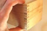 Different types of
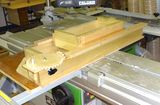 Gerald Finch's box joint jig
 Stepper mictostepping and controlling from Raspberry Pi
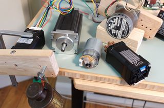 Closed loop stepper motors -- very impressive