 I am often asked about how to set up joints on the
box joint jig.
I am often asked about how to set up joints on the
box joint jig.
I am often asked about how to set up joints on the
box joint jig.
One of my favourite methods is making 1/4" box joints, or finger joints without using a dado blade. I previously touched on this technique in this article, but I thought I'd cover it again in more detail.
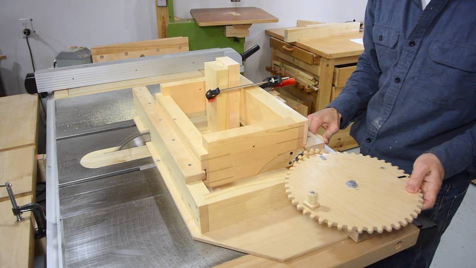
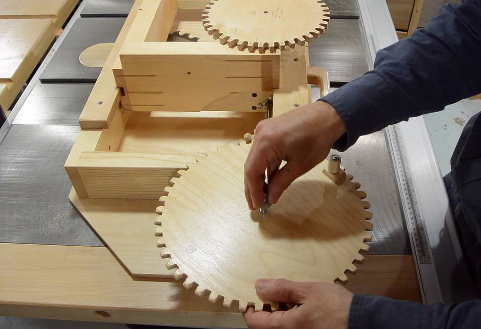 For this joint, I'm using a 48 tooth gear, which I'm meshing with the 12
tooth secondary gear on the threaded rod. This turns the threaded rod
by 4 turns for every turn of the crank on the gear.
For this joint, I'm using a 48 tooth gear, which I'm meshing with the 12
tooth secondary gear on the threaded rod. This turns the threaded rod
by 4 turns for every turn of the crank on the gear.
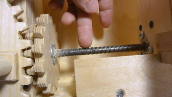 With a 16 tooth per inch threaded rod, that moves the carriage with the
stock in it by 1/4 inch for every turn of the crank. (For metric
countries, a M10 threaded rod with a 1.5 mm thread pitch
will cause the carriage to move 6 mm for every turn of the crank)
With a 16 tooth per inch threaded rod, that moves the carriage with the
stock in it by 1/4 inch for every turn of the crank. (For metric
countries, a M10 threaded rod with a 1.5 mm thread pitch
will cause the carriage to move 6 mm for every turn of the crank)
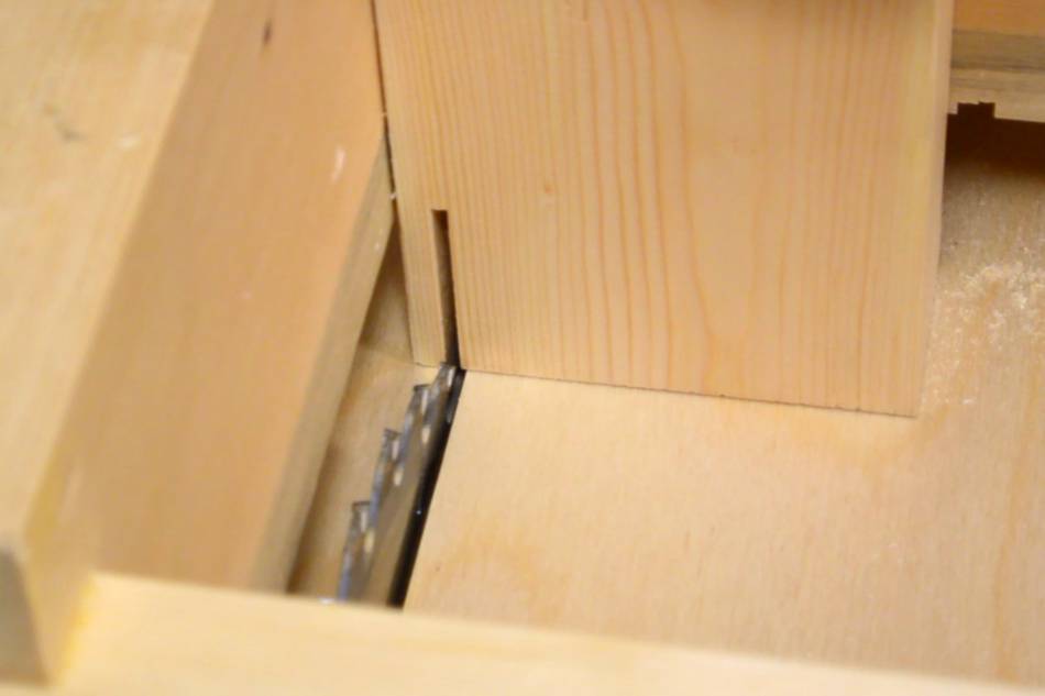
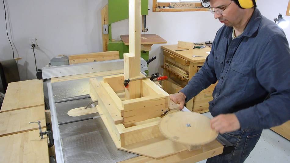
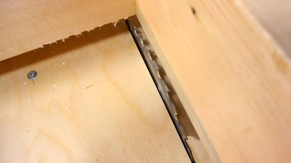 I'm using just a regular "thin kerf" saw blade. I start by aligning the
carriage (or stock holding box) so that its inside right edge is lined
up with the blade's right-side edge.
I'm using just a regular "thin kerf" saw blade. I start by aligning the
carriage (or stock holding box) so that its inside right edge is lined
up with the blade's right-side edge.
Once positioned, I un-mesh the crank gear and reposition it so that the crank handle is next to where it meshes with the 12-tooth secondary gear. I'll call this "home position"
 I then clamp a scrap of wood in the jig, and turn the crank
counterclockwise one turn, which moves the carriage right by 1/4". I
then make a cut.
I then clamp a scrap of wood in the jig, and turn the crank
counterclockwise one turn, which moves the carriage right by 1/4". I
then make a cut.
The picture at left is looking into the jig from behind the saw, so, for the view in the picture, the carriage was moved 1/4" left before the cut.
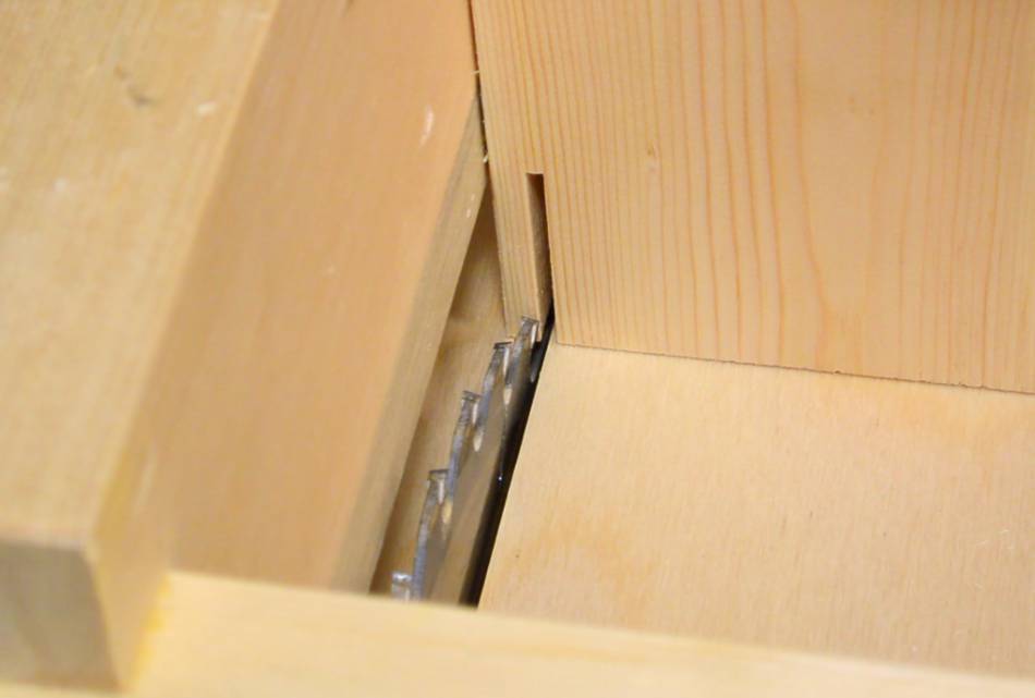 Next I turn the crank clockwise by half a turn, and then slowly turn it
counterclockwise again until the left edge of the blade is aligned with
the right edge of the slot (or, from the point of view from behind
the saw, the right edge of the blade lines up with the left edge of
the slot).
Next I turn the crank clockwise by half a turn, and then slowly turn it
counterclockwise again until the left edge of the blade is aligned with
the right edge of the slot (or, from the point of view from behind
the saw, the right edge of the blade lines up with the left edge of
the slot).
Because the gearing, threaded rod and nut have some backlash in them, it's important to approach all cutting positions from the same direction. That is, the final adjustment is always done by turning the crank counterclockwise. This ensures that any error from backlash is always in the same direction, so cuts are consistent.
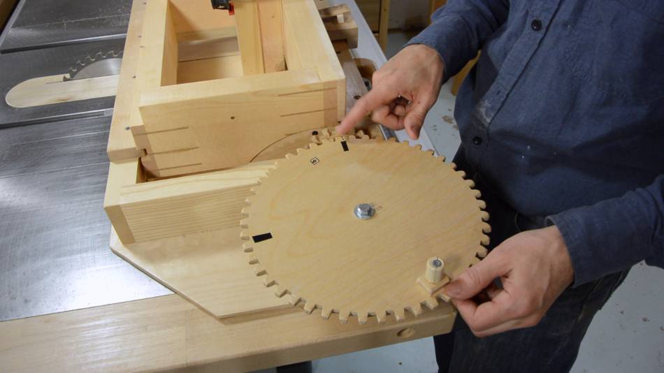
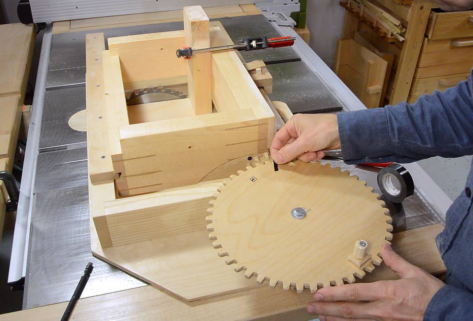 I now mark the position of the large gear with a piece of electrical
tape, placed where it meshes with the small gear.
I now mark the position of the large gear with a piece of electrical
tape, placed where it meshes with the small gear.
The crank position with the black tape denotes the crank angle for the left edge of a slot. The other edge of the slot is when the crank handle is next to the small gear.
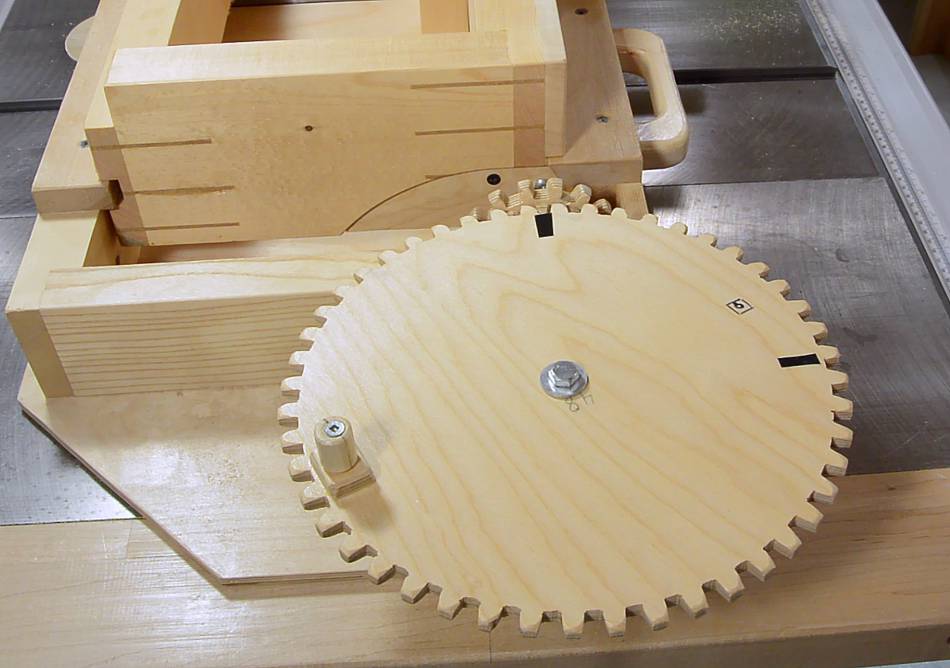 This blade only has a 0.1" kerf, so to hog out 0.25" a third cut
needs to be made. This cut needs to be about half-way between the other
two cut positions, so I add another piece of electrical tape
to mark this cut position.
This blade only has a 0.1" kerf, so to hog out 0.25" a third cut
needs to be made. This cut needs to be about half-way between the other
two cut positions, so I add another piece of electrical tape
to mark this cut position.
 Next I crank the carriage back to home position and clamp two scraps of
wood in the carriage. One of the scraps of wood is offset by 1/4", so
that the two pieces will line up when they mesh.
Next I crank the carriage back to home position and clamp two scraps of
wood in the carriage. One of the scraps of wood is offset by 1/4", so
that the two pieces will line up when they mesh.
Then, to cut the joints, I make a cut at home position, turn about 1/4 turn counterclockwise to the first tape mark, cut again, turn counterclockwise to the second tape mark (again about 1/4 turn on this setup), and cut again. These three cuts have just hogged out a 1/4" slot. Now, turning the gear counterclockwise until the crank handle is next to the secondary gear, I will have moved the stock by 1/4" to the right. So I turn the crank another full turn, and I'm at 1/2" from the starting position, which is also where the next slot starts. I then repeat the above procedure until all the slots are cut.
 From each mark on the gear, I know how far along I am, so even if my
mind drifts, I just have to look at the gear to know where in the sequence
I am. Another approach would be to put a ruler on the jig
like on Yean-Yves's jig
From each mark on the gear, I know how far along I am, so even if my
mind drifts, I just have to look at the gear to know where in the sequence
I am. Another approach would be to put a ruler on the jig
like on Yean-Yves's jig
Test fitting the first joint, it was a bit hard to push the pieces together. So I decided to loosen the fit by cutting the slots slightly wider. To do that, I take the tape marking the final cut of each slot, and move it by half a tooth clockwise on the crank.
 Now, again cutting the joint.
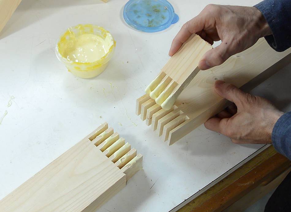 If you make a lot of joints, it makes sense to make a comb for applying the glue.
I made this one with fingers about 3 mm wide, for applying
glue to four slots at a time. I made it on my box joint jig, but
making a fourth cut each time with the crank next to the gear, so that the
slots of the comb are wider, and the fingers narrower.
If you make a lot of joints, it makes sense to make a comb for applying the glue.
I made this one with fingers about 3 mm wide, for applying
glue to four slots at a time. I made it on my box joint jig, but
making a fourth cut each time with the crank next to the gear, so that the
slots of the comb are wider, and the fingers narrower.
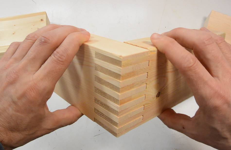
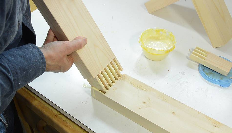 It's always satisfying to assemble a joint like this.
 With this joint being just a demonstration piece, I figured I might as well
break it to see how strong it is. Clamped to the column in my shop,
it just barely held my weight for a few seconds before the wood broke.
With this joint being just a demonstration piece, I figured I might as well
break it to see how strong it is. Clamped to the column in my shop,
it just barely held my weight for a few seconds before the wood broke.
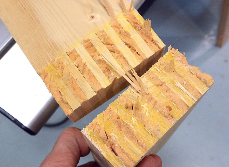
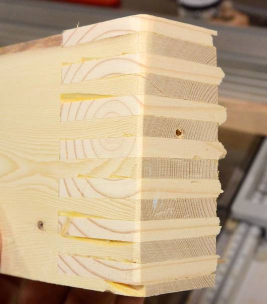 Examining the breakage, it was clear that the 2x4 with the wider growth
rings was much weaker wood. The joint itself stayed intact, but the
wood broke right at the joint, being weakened from half the material
cut away for the joint itself.
Examining the breakage, it was clear that the 2x4 with the wider growth
rings was much weaker wood. The joint itself stayed intact, but the
wood broke right at the joint, being weakened from half the material
cut away for the joint itself.
The joint itself showed no sign of damage. I wish I had used slower
growing wood for both pieces. I'm sure it could have held a lot more
that way.
See also:
Setting up a finger joint on the box joint jig (video)
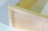 Box joined drawers
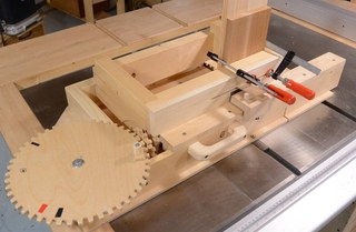 Screw advance
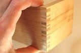 More on box joints
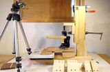 Dovetail vs box joint
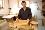 A four-part video series on building the box joint jig