 CFD Analysis of a Blower for a Small Dust Collector
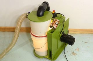
This analysis was primarily intended as an example demonstrating Symscape's computational fluid dynamics software. My dust collector was a good target because the exact geometry was readily available from my plans, and I wrote a fair bit about it on my website.
This page is mostly to summarize how I found these simulations useful. You should also read the blog articles linked below.
CFD Analysis of a Blower for a Small Dust Collector
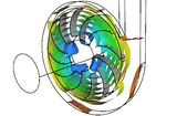
In his first blog post, Richard analyzed the blower. Richard simplified the model to make the vanes of the rotor go from one side of the enclosure to the other, rather than sandwiched between the two rotor disks. This eliminated the rotor disks and regions of extremely high wind shear between the disks and the enclosure. Simulating these as well would have made for dramatically longer computations. However, that, and the modeling of perfectly smooth surfaces no doubt makes the blower perform better in simulation than in real life. On a real blower, air leaking back to the inlet between the front rotor disk and the enclosure will cause some losses, as would turbulence between the rotor disks and the enclosure.
I would have loved to see analysis of the effects of different shapes of vanes in the blower. But I wasn't paying for the simulation work, so can't complain.
Of the 12 vanes of the blower, I extended four to go closer to the center, to help get the air spinning nearer the center, which should get a bit more pressure. But on close examination of the iso surface plots, these four vanes have an effect on the air flow between the vanes all the way out to the edges, and could, presumably, cause a sound at 4x the rotor speed (about 230 Hz). If it does cause a sound at that frequency, it's definitely less annoying than the principal sound at 700 Hz from the 12 vanes though.
The sound, and the tin-can resonator would be another interesting thing that could potentially be explored in simulation. But you could really go down a rabbit hole analyzing this sort of thing!
 CFD Analysis of a Homemade Cyclone
To me, the cyclone was the most interesting part of the simulation. When I measured my first cyclone, I realized that a cyclone was quite an interesting "beast", so to say.
Richard limited his analysis to just the airflow, as the software currently doesn't handle fluids mixed with particles.
The simulated cyclone showed a great deal of pressure drop in the cyclone, which was in line with measurements I made on my dust collector (though I didn't write about those).
When I probed around the inside of my first cyclone, I found a great deal of pressure difference between the outside and inside of the cyclone, and also areas of greater vacuum inside the cyclone than at the blower that pulled air from the cyclone. In other words, the cyclone was creating greater vacuum inside it than is sucked from it.
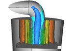
If you look at the pressure iso-surfaces, the dark blue regions inside the cyclone represent a lower pressure than at the outlet (in the simulation, zero pressure refers to the outlet pressure). Also note the very high pressure gradient near the outlet. The speed of the swirling air near the outlet is also the highest in the whole cyclone, twice as fast as the air streaming into the inlet. It's counterintuitive that the air should speed up as it gets to the middle, but by conservation of angular momentum, the air has to speed up as it gets to the middle.
It's the centrifugal force of the air moving fast around a tight circle that makes for the pressure drop. With the air over 30 meters per second near the outlet and rotating in a circle about 9 cm in diameter, it's spinning at over 100 turns per second, or 6000 RPM
Any obstruction in the cyclone that slows down this swirling of air will reduce the pressure drop. So, ironically, adding obstructions can reduce its air resistance. However, it's this rapidly spinning air that also spins out the dust. This is a fundamental problem of cyclones - the spinning air separates dust, but also causes a big pressure drop.
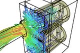 CFD Simulation of Airflow Through Filters in a Dust Collector
By my measurements, the filter box and manifolds make small contributions to
pressure drop, and the simulations agreed. Convoluted air paths make for
more air resistance, but having wide paths for the air makes for lower air speed.
For turbulent flow, pressure drop
is mostly a function of flow rate squared. Doubling the area of a channel
will halve the air speed, but cut pressure drop to
one quarter. Given the filter box's small contribution to pressure drop,
it's the least critical part of the dust collector in terms of performance.
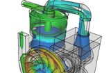 CFD for a complete dust collector
An analysis of all the components of the dust collector as one simulated model (as opoosed to by component)
The Graph titled "Volume Flow Rate Monitor" shows the flow rate increasing to over 0.1 cubic meters per second, then dropping back down to 0.8. This is consistent with the cyclone spinning up. Once the air in the cyclone is fully spun up, it causes a lot of back-pressure, and correspondingly lower flow rate. However, on my cyclone, I see this happening in less than a second, and the graph shows this happening in 50 seconds. I asked Richard about this. Turns out, the time scale is not to scale.
Also, I can only observe this on my dust collector if I block the inlet and open it suddenly. When it starts up, it takes the motor several seconds to get up to speed. With the cyclone spinning up in less than a second, it keeps up with the motor.
I also find the various diagrams of pressure and velocity interesting to
study, though I can't think of anything specific to point out.
It's very tempting to get into CFD analysis myself to investigate some of these things further. For optimizing something like a blower or cyclone, where design changes are a lot of work, and small changes in performance are hard to measure, CFD is definitely the way to go.
But doing CFD analysis requires some skill with the software, the software
(usually not cheap), a much faster computer, and a lot of time to run the
simulations. It's a rabbit hole I will, for the time, resist going down.
 Small dust collector
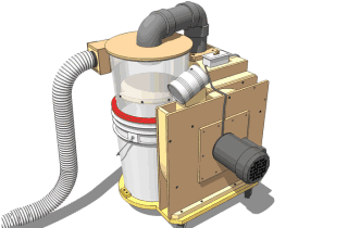 Dust collector plans
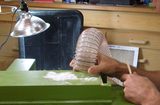 Analyzing the cyclone
 Mini tornado experiment
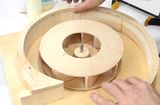 Blower impeller design experiments
 2 x 45° elbow vs. 90° elbow air resistance test