 In North America, many single phase motors motors in the range of 1 hp to 2 hp can
be rewired to run at either 120 volts or 240 volts (or 115 vs 230 volts, it
depends on what voltage is assumed "nominal").
In North America, many single phase motors motors in the range of 1 hp to 2 hp can
be rewired to run at either 120 volts or 240 volts (or 115 vs 230 volts, it
depends on what voltage is assumed "nominal").
In North America, many single phase motors motors in the range of 1 hp to 2 hp can
be rewired to run at either 120 volts or 240 volts (or 115 vs 230 volts, it
depends on what voltage is assumed "nominal").
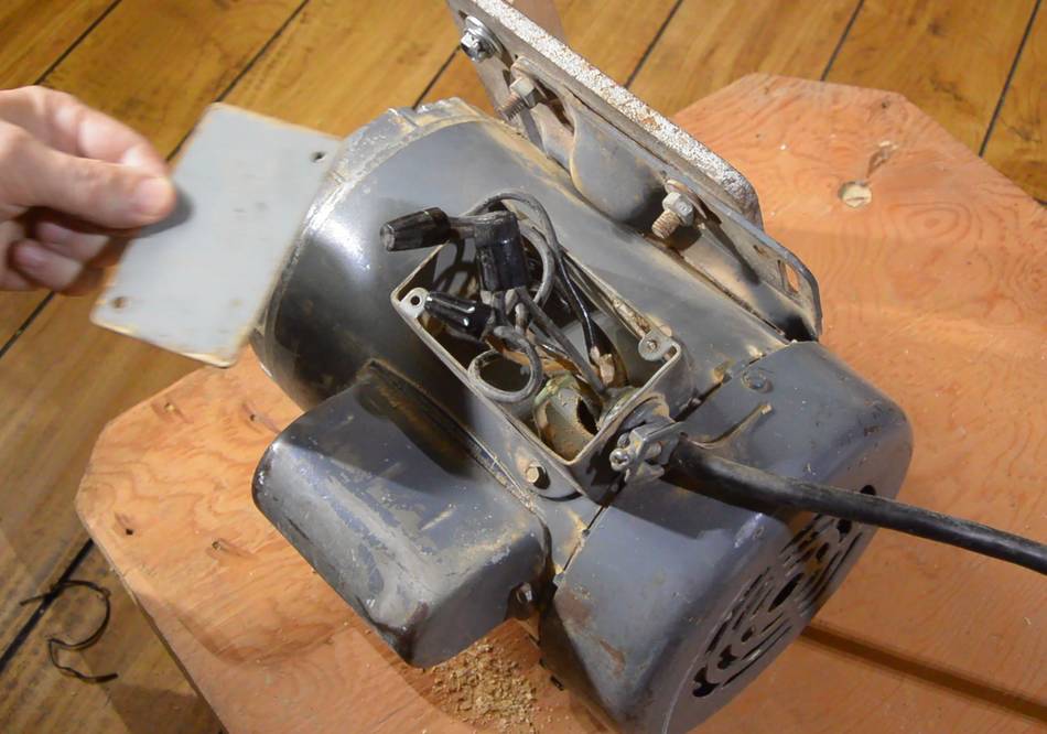
Such motors will typically have six leads coming out of the motor to the wiring box, or some of the connections may be screw terminals. The best way to change the voltage on a motor is to follow the wiring diagram on the label. But sometimes when you open up a motor, there's just six wires and no diagram! This happened to be the case for the 1.5 hp motor on my old table saw. 20 years ago I wired it to 240 volts, but I wanted to switch it back to 120 volts. for where I moved it to.
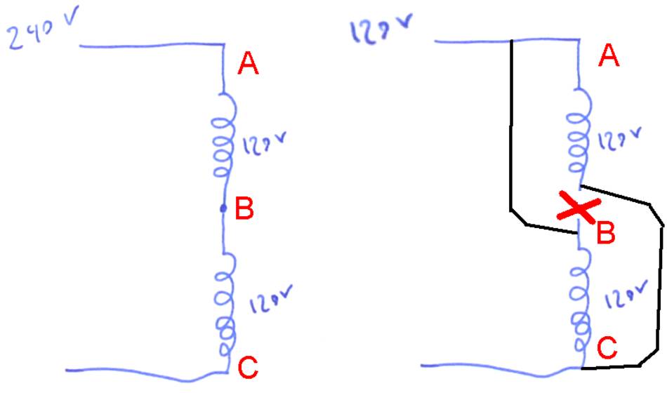 Internally, the motor has two 120 volt windings, which are in series
when the motor is wired for 240 volts (left, at left).
When switching it to 120 volts, the two windings are reconfigured to be in parallel.
Internally, the motor has two 120 volt windings, which are in series
when the motor is wired for 240 volts (left, at left).
When switching it to 120 volts, the two windings are reconfigured to be in parallel.
It would be easier to connect A to C, and then connect power to B. But this will switch the polarity of the winding between A and B, which means winding A-B would be fighting winding B-C. If you then plugged it in like that, the motor would draw about 100 amperes, but it wouldn't run. If the circuit breaker didn't pop right away, the motor would start to smoke within ten seconds.
But it's not that simple: There is also a starter winding
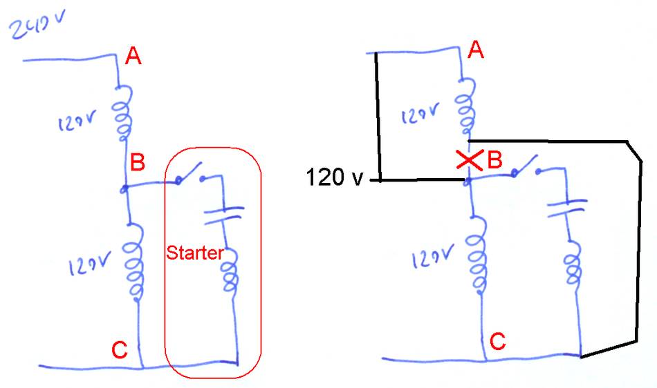 But it's actually more complicated than illustrated above. The motor also has
a starter winding, which is in series with a starter switch and starter capacitor
(see red outline at left). The starter winding is only active while the motor
is spinning up to speed.
But it's actually more complicated than illustrated above. The motor also has
a starter winding, which is in series with a starter switch and starter capacitor
(see red outline at left). The starter winding is only active while the motor
is spinning up to speed.
If the starter winding and capacitor also needed to be reconfigured for voltage changes, the wiring would be quite a nightmare!
So instead, the starter winding in these motors is always a 120 volt winding, and the motors two 120 volt windings are used as an autotransformer to make the 120 volts for the starter winding. Reconfiguring between 240 and 120 volts is done the same way, but the starter winding stays connected to one of the windings.
If you don't have a wiring diagram, and the motor is currently wired for 240 volts, you can identify point "B" by the fact that it isn't connected to either power lead. Using an ohm meter, check which of the three wires from B lead to the power lead with just one wire attached to it. That's the one you need to disconnect and connect to C. And the winding end at A needs to be brought to B.
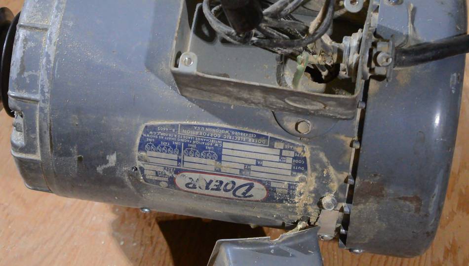
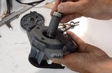
 After working this out, I realized, 20 years ago, I moved the starter capacitor mount on
this motor so it wouldn't protrude above the table saw table when the blade is
tilted 45 degrees. And in moving the capacitor, I ended up mounting it right over
the motor's label plate, which also shows the wiring.
So removing the capacitor cover, I could see the label, complete with wiring diagram
and I was able to check my work before I plugged it in.
After working this out, I realized, 20 years ago, I moved the starter capacitor mount on
this motor so it wouldn't protrude above the table saw table when the blade is
tilted 45 degrees. And in moving the capacitor, I ended up mounting it right over
the motor's label plate, which also shows the wiring.
So removing the capacitor cover, I could see the label, complete with wiring diagram
and I was able to check my work before I plugged it in.
Using an ohm meter, find a pair of leads that has less than 5 ohms between them. The reading should not change as you hold the meter on those. Label these wires 1 and 2. 1 and 2 shouldn't have any conductivity to any other leads coming out. Now find another pair of wires with the same resistance as 1 and 2 between them, Label these 3 and 4. 1-2 and 3-4 are the main windings.
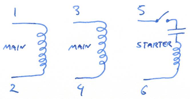 The remaining two leads should connect to the starting capacitor, starting switch,
and straiting winding in series (with the motor not running, the starting switch
will be closed).
Label these remaining leads 5 and 6.
If you measure the resistance between 5 and 6, you should see the
reading on your meter continually increasing (set your meter to something other
than the lowest ohm range). If you
swap the meter probes between 5 and 6, the resistance reading will be lower again,
but again go up. You are measuring resistance across the capacitor, and as it
"charges up" from the meter applying current to measure,
the resistance reading will go up.
The remaining two leads should connect to the starting capacitor, starting switch,
and straiting winding in series (with the motor not running, the starting switch
will be closed).
Label these remaining leads 5 and 6.
If you measure the resistance between 5 and 6, you should see the
reading on your meter continually increasing (set your meter to something other
than the lowest ohm range). If you
swap the meter probes between 5 and 6, the resistance reading will be lower again,
but again go up. You are measuring resistance across the capacitor, and as it
"charges up" from the meter applying current to measure,
the resistance reading will go up.
For 120 volt operation, you need to either connect
1,3,5 to one power lead and 2,4,6 to the other OR 1,4,5 and 2,3,6. But which one??
If you get it wrong, you will blow the circuit breaker or destroy the motor. Basically, if winding 1-2 is opposing winding 3-4, very bad things happen.
You can, for a short time, run the motor off 120 volts using just one of the 120 volt winding. So just leave leads 3 and 4 disconnected. Connect one power lead to 1,5, the other to 2,6, and plug it in to 120 volts. The motor should run.
Unplug the motor, now add lead 3 to 1 and 5 (1,3,5 and one of the power leads all together), and leave just 2,6 to the other power lead. Plug in the motor, while it runs, measure the voltage between the remaining unconnected lead 4 and the other lead supplying power, connected to leads 2,6). If the voltage is less than 10 volts, then you can connect lead 2,4,6 together. Your motor is now wired for 120 volts.
If the reading is over 200 volts, then you need to swap leads 3 and 4. Re-label lead 3 as 4, and 4 as 3, then repeat the step above and make sure the difference reading is less than 10 volts.
To reverse the motor, swap leads 5 and 6 (the ones that go to the starter winding)
To wire the motor for 240 volts, connect lead 1 to one power lead
connect leads 2,3,5 together (without connecting them to either power lead)
Connect the other power lead to 4,6.
If the motor has screw posts in the wiring box, there will be an extra screw post,
not connected to anything, for connecting leads 2,3,5 together.
And as before, to reverse the motor, swap leads 5 and 6
If this doesn't work for you, it's possible that the motor is not a dual voltage single phase motor, or there is something wrong with it. Feel free to email me. I probably won't be able to help you, but it's useful to know where you run into problems. That way, if a lot of folks get hung up on the same problem, I might be able to add some notes about that.
And if you blow up a motor or it catches fire, don't blame me!
 dishwasher wet rotor synchronous motor
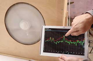 Measuring RPM with a spectrum analyzer app (video only)
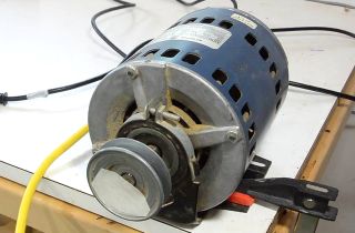 How AC induction motors work
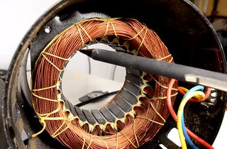 Reversing single phase induction motors
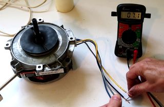 Figuring out a mystery motor
 Where do you get your motors from?
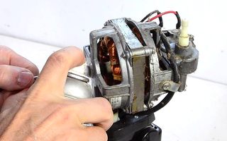 Fixing seized oscillating fan motor
 Motorizing the apple grinder
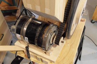 Motorizing the bandsaw
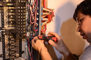 Installing a 240 volt circuit