Michael Sexton's ball mill
Michael Sexton sent me some pictures of the ball mill that he built using wooden gears drawn with the gear template generator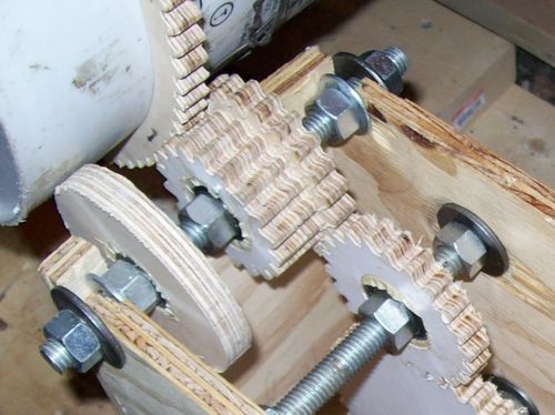
Michael writes:
"This design has turned out rather well. Those are steel bearings in the center of each gear. They are held in by a press fit (forstner bit with a bit of tape around the bearing). They hold up to wear pretty well. I have had this on running for a total of about 4 hours, so it is just getting broken in. The gears exhibit no signs of wear unless the mass inside the ball mill container is too great."
I love this application. This is the first time I have seen this type of plywood gears seen in a real power application. So far, I have only used plywood gears for hand-cranked applications, such as this router lift, where wear has never been a factor.
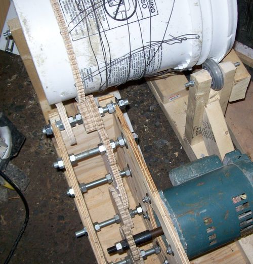
"The reason for the wire around the ball mill
container is to keep the ring gear from slipping. I couldn't believe the amount of
force that the steel balls exerted on the container. I had the ring gear on rather tight,
and the rolling/banging action of the balls still managed to make the gear slip.
The wire is wrapped around in a spiral pattern so as to exert force in the opposite
direction of the slip. This way, when the ring gear attempts to slip, it is like
tightening a knot."
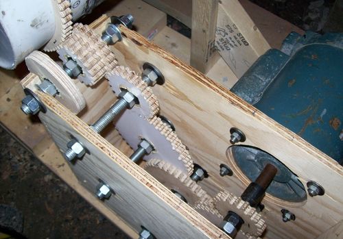
"I probably could have used fewer gears had I used the pin type gears from your gear program.
All of the gears in the box are 1 of three sizes. Anyway, so far it works quite well,
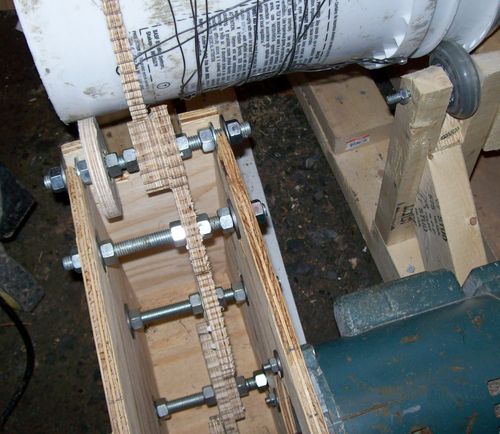
I have powderized glass for use in re-melting (pulverised using 1 inch diameter steel
balls - about 40 of them). The gears prevent slippage of the ball mill container,
which I had problems with earlier. I will talk to you later!"
- Mike
I think Mike did well sticking to involute gears. I don't think the pinwheel type gears are that good for power transmission.
More Reader projects