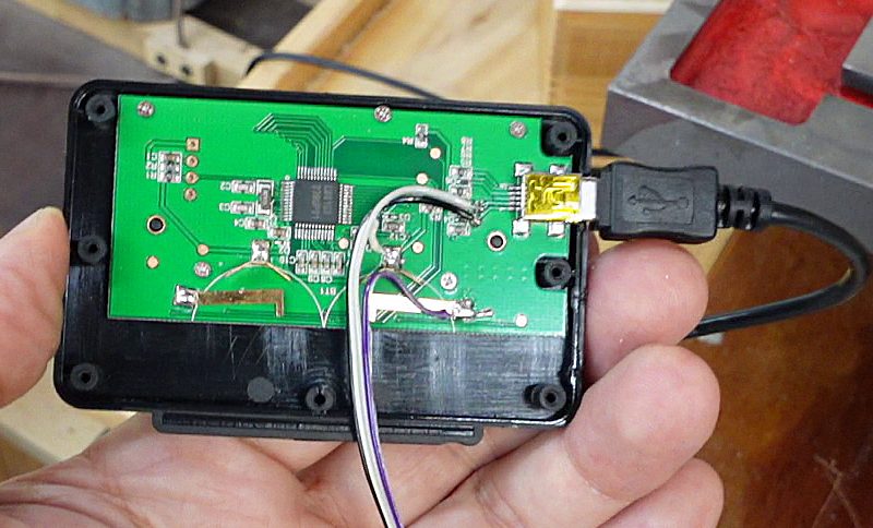
 I had previously connected these to raspberry pi comptuers by opening up the
display module and soldering wires to the synchronous serial lines coming
from the sensor module and connecting those to GPIO lines on the Raspberry Pi.
I had previously connected these to raspberry pi comptuers by opening up the
display module and soldering wires to the synchronous serial lines coming
from the sensor module and connecting those to GPIO lines on the Raspberry Pi.
I had previously connected these to raspberry pi comptuers by opening up the
display module and soldering wires to the synchronous serial lines coming
from the sensor module and connecting those to GPIO lines on the Raspberry Pi.
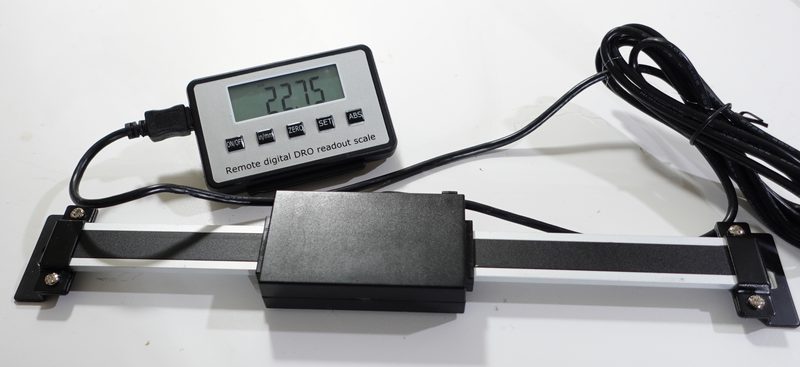
 This allowed me to read the sensor from both the display module and Raspberry
Pi at the same time. But the procedure is rather invasive. I have since
come up with a more elegant method of connecting these to a Raspbery Pi.
This allowed me to read the sensor from both the display module and Raspberry
Pi at the same time. But the procedure is rather invasive. I have since
come up with a more elegant method of connecting these to a Raspbery Pi.
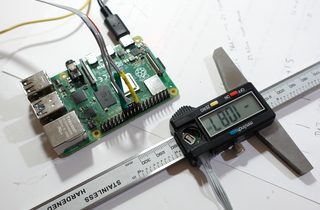
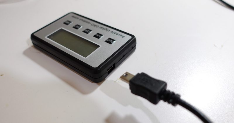 The actual sensor module connects to the display module with a mini-USB connector.
The connection is not USB, and the pinoutr does not follow USB conventions,
so don't try to plug these into your computer or Raspberry Pi directly.
The actual sensor module connects to the display module with a mini-USB connector.
The connection is not USB, and the pinoutr does not follow USB conventions,
so don't try to plug these into your computer or Raspberry Pi directly.
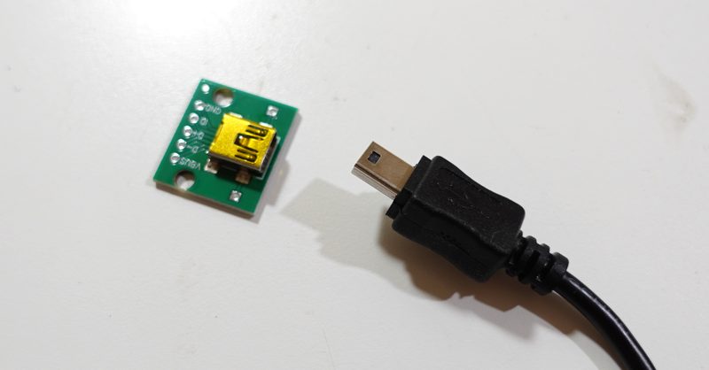 So I bought some female mini-USB breakout boards on amazon.
These have a female mini-USB socket and bring the five pins out to normal 0.1" spacing.
Only four of the pins are used by the sensor module. I sanded the board down to not take up as much space, as the Raspberri Pi GPIO header can get crowded when I connect multiple peripherals to it.
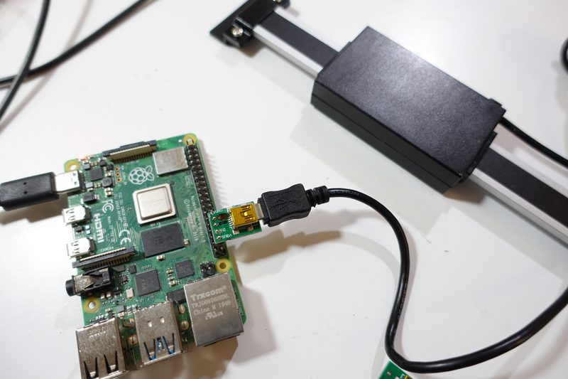 The sensor normally runs on 3.2 volts from the battery, so I figured 3.3 volts from the
Pi should be safe. I just pluggd it in so that one of the Pi's ground pins on the header
corresponded to the pin that the SHAHE encoder uses as ground.
The sensor normally runs on 3.2 volts from the battery, so I figured 3.3 volts from the
Pi should be safe. I just pluggd it in so that one of the Pi's ground pins on the header
corresponded to the pin that the SHAHE encoder uses as ground.
My connections are as follows:
| MINI USB pin | Pi Header pin | Pi GPIO | Sensor Function |
|---|---|---|---|
| 1 | 30 | 20 | Clock |
| 2 | 36 | 16 | Data |
| 3 | 34 | GND | Gnd |
| 4 | 38 | 12 | +3.3 V |
| 5 | -- | -- | Unused |
Pi GPIO 12 (pin 38) is set to output high to provide 3.3 volts. I could of course have used one of the 3.3 volt pins on the pi header, but I wanted to keep it to four consecutive pins on the header so that I only needed to solder a female header to the bottom of the board.
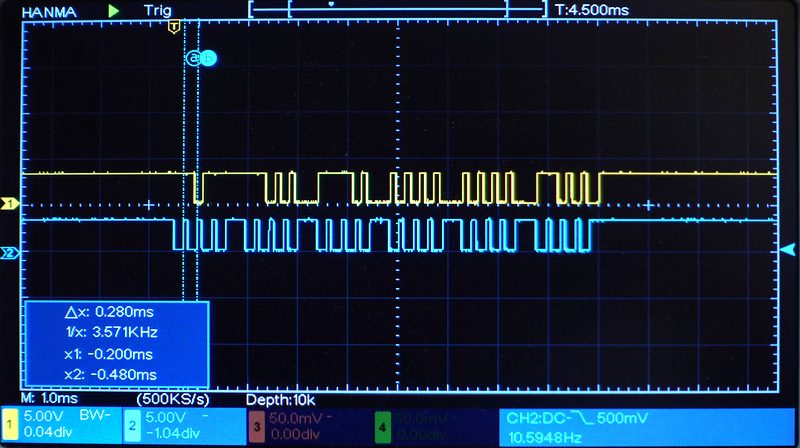 The output from the sensor is a 24 bit word, sent as synchronous serial at about 3.5 kilobits
per second. The position is sent times per second.
The output from the sensor is a 24 bit word, sent as synchronous serial at about 3.5 kilobits
per second. The position is sent times per second.
But for some reason, the clock intervals are not all the same length, which
had me confused at first, but that is perfectly ok for synchronous serial.
The clock output is normally high, then when it goes low and back to high, the "high" interval of the clock is the valid data period, so on each rising edge, read the data line and add that to the word being received. Data bits are sent LSB first, 24 bits in total. Once the clock line stays high, that is the end of the word.
The bit rate from the sensor is low enough that it's possible to decode the output from multiple sensors using a Raspberry Pi 3 in Python. But python is not real time, and on rare occasions, it will miss a bit due to interruptions or python garbage collection. To detect when this happens, my phython code checks that the clock is still high after reading the data pin and also counts the number of bits received to ensure its 24. If either condition is false during the read, the result is discarded.
Using this method, I have so for always detected the occasional failed read and just not used that reading. I have never seen it pass an invalid reading.
Download my code:
decode_shahe.py
 Decoding digital calipers (2025)
 Anemometer interface for Raspberry Pi
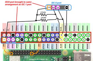 Using the second (I2C 0) port on Raspberry Pi
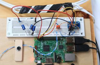 Inductive current measuring using Raspbery Pi