Wiper-motor powered forklift toy
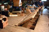
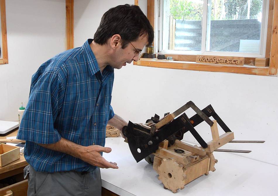 When I did the video tour of my dad's shop attic,
I showed this forklift toy
that I built in 1985. A lot of people commented that they
wanted to see that thing run again.
When I did the video tour of my dad's shop attic,
I showed this forklift toy
that I built in 1985. A lot of people commented that they
wanted to see that thing run again.
So on my most recent trip to my parents, I brought it back to my shop.
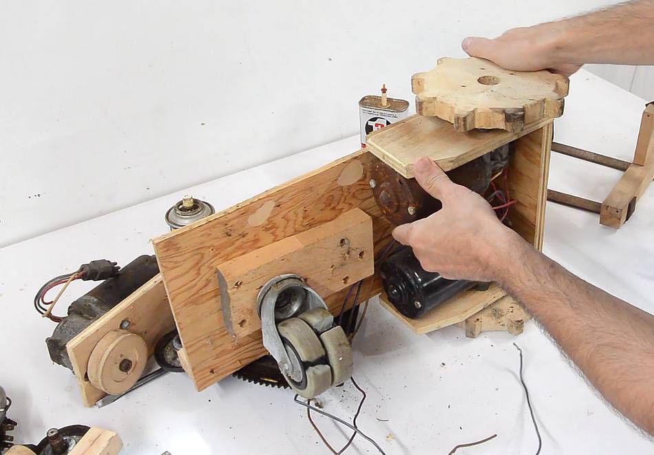
 Each of the two cogged wheels is powered independently by a windshield wiper
motor. The cog wheels were originally round wheels, but I experimented with adding
caterpillar tracks. But the tracks made it nearly impossible for
it to steer, so I switched back to two wheels and a caster, but I kept
the sprocket wheels.
Each of the two cogged wheels is powered independently by a windshield wiper
motor. The cog wheels were originally round wheels, but I experimented with adding
caterpillar tracks. But the tracks made it nearly impossible for
it to steer, so I switched back to two wheels and a caster, but I kept
the sprocket wheels.
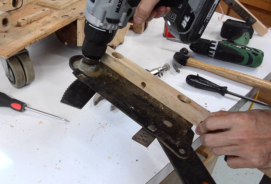 The mechanism for raising and lowering the fork is made of two hand-cranked
window lifters from a 1970s car. But the whole lifting mechanism
was seized up. Taking the window lifters off and adding oil
and turning them with locking pliers, they moved again. I cranked them up
and down a few times with a drill until they turned easily again.
The mechanism for raising and lowering the fork is made of two hand-cranked
window lifters from a 1970s car. But the whole lifting mechanism
was seized up. Taking the window lifters off and adding oil
and turning them with locking pliers, they moved again. I cranked them up
and down a few times with a drill until they turned easily again.
 Flipping it over, you can see the caster wheel in the back. It's been
30 years since I built this thing, and the rubber has shrunk and cracked.
Flipping it over, you can see the caster wheel in the back. It's been
30 years since I built this thing, and the rubber has shrunk and cracked.
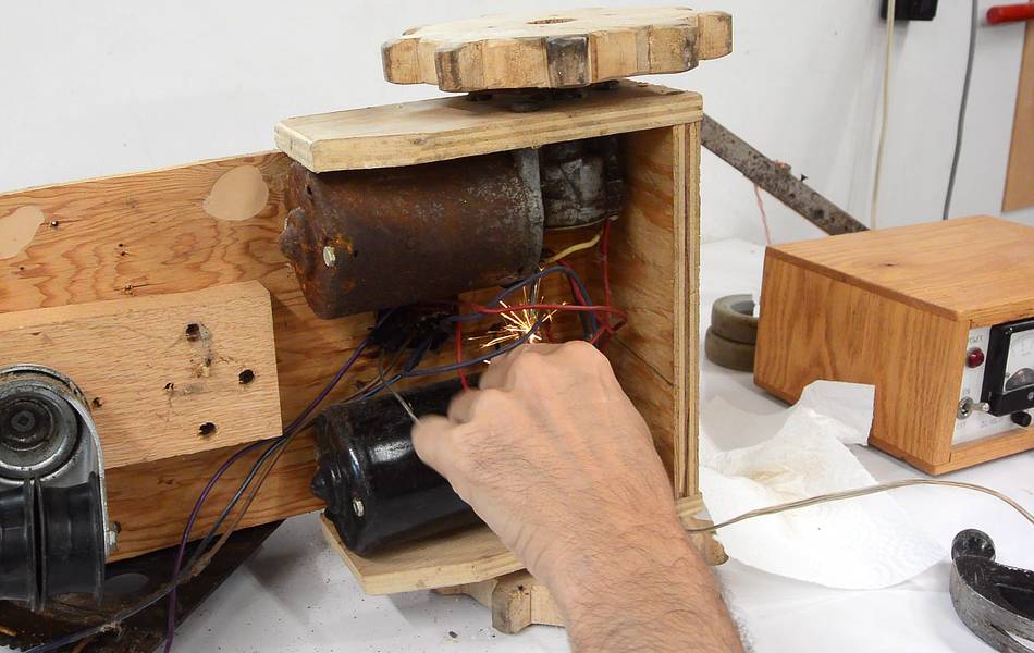 Checking the wiper motors. The top one (the rusty one) would no longer run,
but the other one was still woring.
Checking the wiper motors. The top one (the rusty one) would no longer run,
but the other one was still woring.
Un-seizing the windshield wiper motor
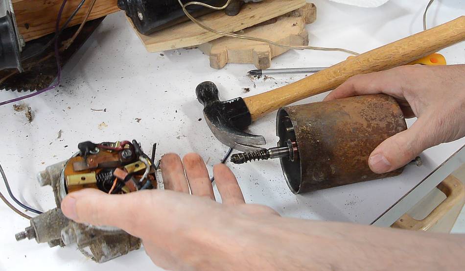
 Not having a spare motor, I opened up this one to see what might
be wrong with it.
Not having a spare motor, I opened up this one to see what might
be wrong with it.
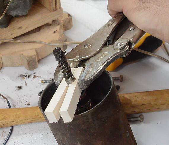
The rotor was stuck in the back housing. I cut two pieces of wood to clamp some locking pliers to the shaft without damaging it. But it wouldn't budge coming out. I could spin it just barely, but I was pretty sure I was spinning the bearing itself (shaft seized in the bearing)
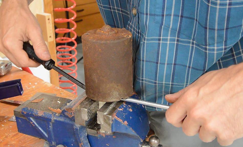 I eventually got it out by clamping the shaft (with the wood blocks)
in the vise and using two screwdrivers to pull up on the housing.
I eventually got it out by clamping the shaft (with the wood blocks)
in the vise and using two screwdrivers to pull up on the housing.

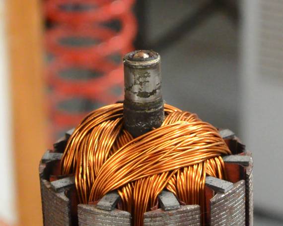 A closer look at the rotor. It looks like the grease in the bearing had turned
into solid gunk. No wonder it wouldn't turn.
A closer look at the rotor. It looks like the grease in the bearing had turned
into solid gunk. No wonder it wouldn't turn.
But some WD-40 sprayed onto it cleaned it off very quickly.
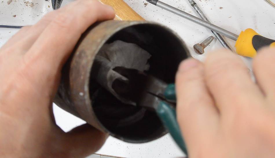 I cleaned up the other bearing the same way, using some paper towel wrapped
around needle nose pliers to wipe out the old gunk. Then applying
some thick oil to all the bearing surfaces.
I cleaned up the other bearing the same way, using some paper towel wrapped
around needle nose pliers to wipe out the old gunk. Then applying
some thick oil to all the bearing surfaces.
 I tied the carbon brushes back with some thin wire so I could insert the
rotor again.
I tied the carbon brushes back with some thin wire so I could insert the
rotor again.
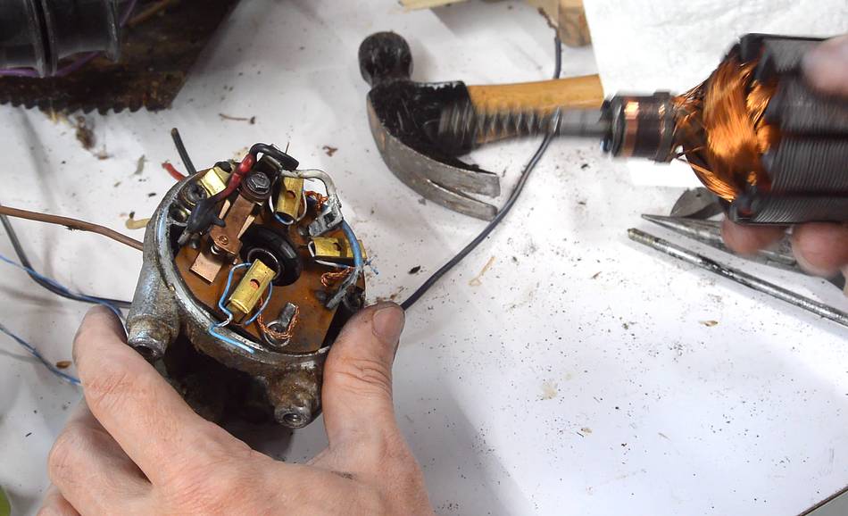
A curious thing about this motor is that it has three brushes. Speed control was achieved by connecting power to different brushes on the motor. In some ways this is inelegant, but still more efficient and more consistent speed than having a resistor in series with the motor. By connecting power across brushes that were closer together, there would be less induced back-EMF, allowing the motor to run faster from the same input voltage. More on how this is wired up in a car here
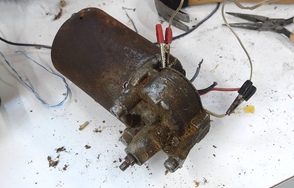 After reassembly, I applied power to the motor again. It now ran smoothly.
 But given how the bearing grease had turned to solid gunk, I figured I should
at least inspect the gearbox. This still looked good, but I added
some fresh oil to thin the grease a little.
But given how the bearing grease had turned to solid gunk, I figured I should
at least inspect the gearbox. This still looked good, but I added
some fresh oil to thin the grease a little.
Cleaning it up
 The whole thing was covered in a layer of dirt and dust from having been in
the attic all this time.
The whole thing was covered in a layer of dirt and dust from having been in
the attic all this time.
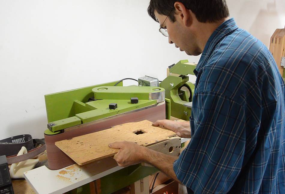
 Having removed all the hardware and brushed off as much dust
as I could, I took it to the belt sander
to sand it down a little.
Having removed all the hardware and brushed off as much dust
as I could, I took it to the belt sander
to sand it down a little.
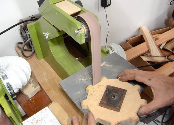
I also sanded down the drive sprockets on my strip sander.
 I applied two coats of varnish. This gives it a bit
of a shine and also makes it possible to clean any new grease off the wood.
I applied two coats of varnish. This gives it a bit
of a shine and also makes it possible to clean any new grease off the wood.
Looking at the whole thing, I have to say, I have gotten much more meticulous about building stuff since I was 16. But I also have much better materials and tools available now. And possibly, I'm spending more time fixing this thing than I did building it in the first place.
 I made the original drive tracks relatively long so that the rear axle would
clear the lifting mechanism. But the long tracks, unfortunately, made
it just about impossible to steer it in anything but a straight line,
especially on grass. So I switched it back to two wheels and a caster.
I made the original drive tracks relatively long so that the rear axle would
clear the lifting mechanism. But the long tracks, unfortunately, made
it just about impossible to steer it in anything but a straight line,
especially on grass. So I switched it back to two wheels and a caster.
 But with the caster now ruined, I figured I might as well try to make the
tracks work. Shortening the tracks substantially makes it more
like a small skid-steer loader, or this other
this tracked toy that I also built
back in 1985.
But with the caster now ruined, I figured I might as well try to make the
tracks work. Shortening the tracks substantially makes it more
like a small skid-steer loader, or this other
this tracked toy that I also built
back in 1985.
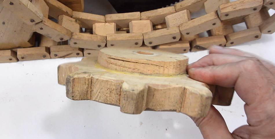 I wanted to reuse the extra sprockets. But I noticed the glue joint
to the extra layer was cracked, then noticed the whole sprocket was warped
and shrunk by several millimeters in the cross-grain direction.
I wanted to reuse the extra sprockets. But I noticed the glue joint
to the extra layer was cracked, then noticed the whole sprocket was warped
and shrunk by several millimeters in the cross-grain direction.
Apparently, the maple wood I used for these wasn't fully dried when I made them.

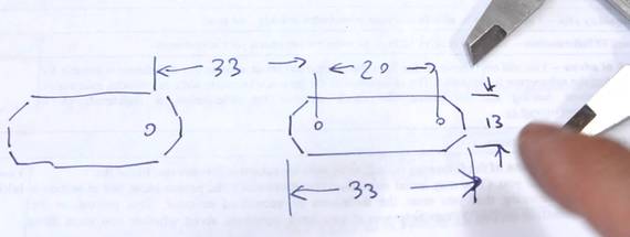 So I measured the parameters of the chain,
then used the "sprocket mode" of
my gear generator program to generate
a shape for new sprockets,
So I measured the parameters of the chain,
then used the "sprocket mode" of
my gear generator program to generate
a shape for new sprockets,
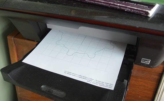 which I printed out...

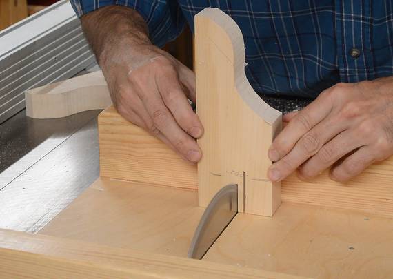
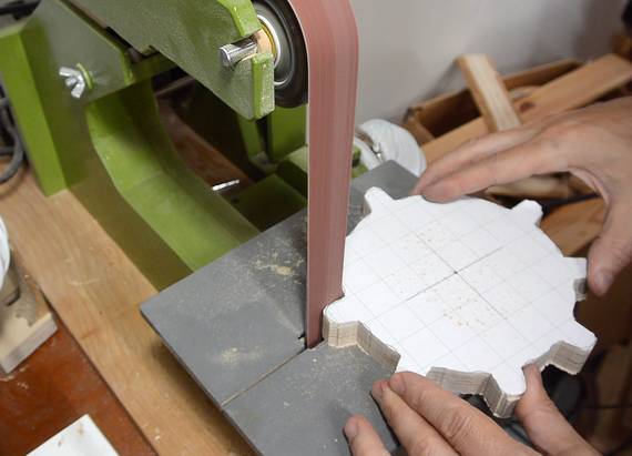 ... and cut out on the bandsaw. I used my
strip sander to smooth the cogs.
... and cut out on the bandsaw. I used my
strip sander to smooth the cogs.

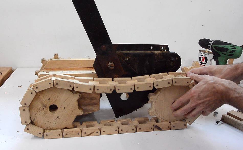
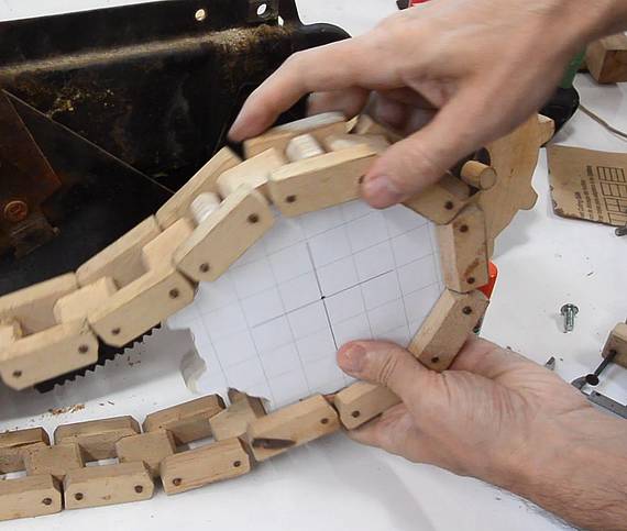 At right, checking the fit of the new sprocket with the chain.
I previously used a 1/2" dowel for the back axle, but a steel axle would be better, and I had a piece of 3/8" steel rod kicking around. I also glued an extra layer of wood on the sprocket around the hole to give it more stability. Again, I have much better materials available to me now than I did when I was 16.
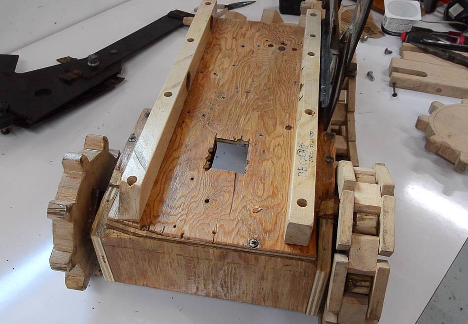
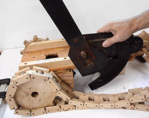
 I needed to cut away part of the lifting mechanism to make the axle fit
in the new location. Here, using an awl to scratch a mark on to the lifting
mechanism for where the axle needs to go.
I needed to cut away part of the lifting mechanism to make the axle fit
in the new location. Here, using an awl to scratch a mark on to the lifting
mechanism for where the axle needs to go.
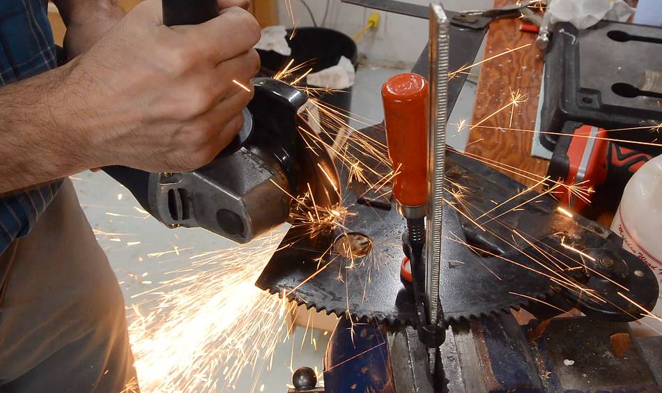
 Then cutting out a notch with an angle grinder.
Conveniently, the mechanism already had a big hole right where the notch needs to be.
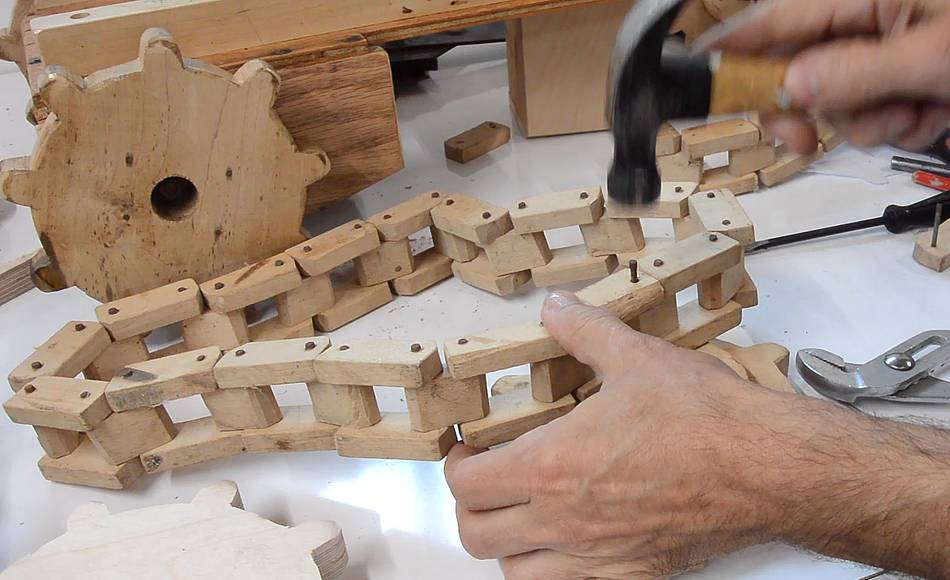 I shortened the chain by punching out one of the nails that holds
it together, then removing links, and driving the nail back in.
I shortened the chain by punching out one of the nails that holds
it together, then removing links, and driving the nail back in.
The nail fits loosely around the block in the middle, but tightly in the blocks on either side. The nails rusted a bit since I built it, and that also helps to lock them in.
 I made two brackets with slots in them to hold the new axle.
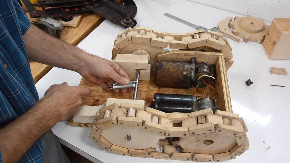
A spring will hold the axle so the chain is fairly taut, but the axle can move a little in case something gets caught in the chain and sprockets.
 The brackets screw on from the top, through the rails that the window
lifters are mounted to. The chassis of this forklift is only 1/4"
thick plywood, and not even very good plywood. So screwing through the rail
on top into the bracket on the bottom gives it much better support.
The brackets screw on from the top, through the rails that the window
lifters are mounted to. The chassis of this forklift is only 1/4"
thick plywood, and not even very good plywood. So screwing through the rail
on top into the bracket on the bottom gives it much better support.
 I drilled holes through the ends of the axle so I could put a pin through
them to help hold the sprockets in place.
I drilled holes through the ends of the axle so I could put a pin through
them to help hold the sprockets in place.
 A bent nail keeps the sprocket (and washer) from sliding off. A cotter pin
would be more appropriate, but a bent nail works too.
A bent nail keeps the sprocket (and washer) from sliding off. A cotter pin
would be more appropriate, but a bent nail works too.
 Installing the axle. Also note the spacer between the right sprocket
and the bracket.
Installing the axle. Also note the spacer between the right sprocket
and the bracket.
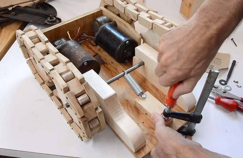 Spring installed, with a block of wood to hook it onto. I pulled the block
of wood back until the spring was taut, clamped it in place, then screwed
it on from the top, through the plywood.
Spring installed, with a block of wood to hook it onto. I pulled the block
of wood back until the spring was taut, clamped it in place, then screwed
it on from the top, through the plywood.
 Now re-installing the wiring connector.
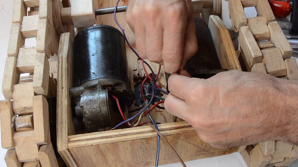 The connections on the bottom are just nade by twisting the copper wires
together. I figure I may need to take motors out again for servicing, so I
didn't want to solder the wires.
The connections on the bottom are just nade by twisting the copper wires
together. I figure I may need to take motors out again for servicing, so I
didn't want to solder the wires.
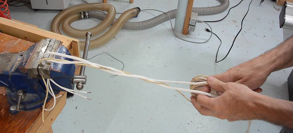 With a total of four wiper motors and no electronics or relays, I need four
wires plus a common ground to connect all of them. I made a five lead strand
by braiding together two lamp cords plus a thicker piece of automotive
wiring for ground.
With a total of four wiper motors and no electronics or relays, I need four
wires plus a common ground to connect all of them. I made a five lead strand
by braiding together two lamp cords plus a thicker piece of automotive
wiring for ground.
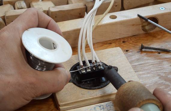 Then soldering the wire strand onto the connector.
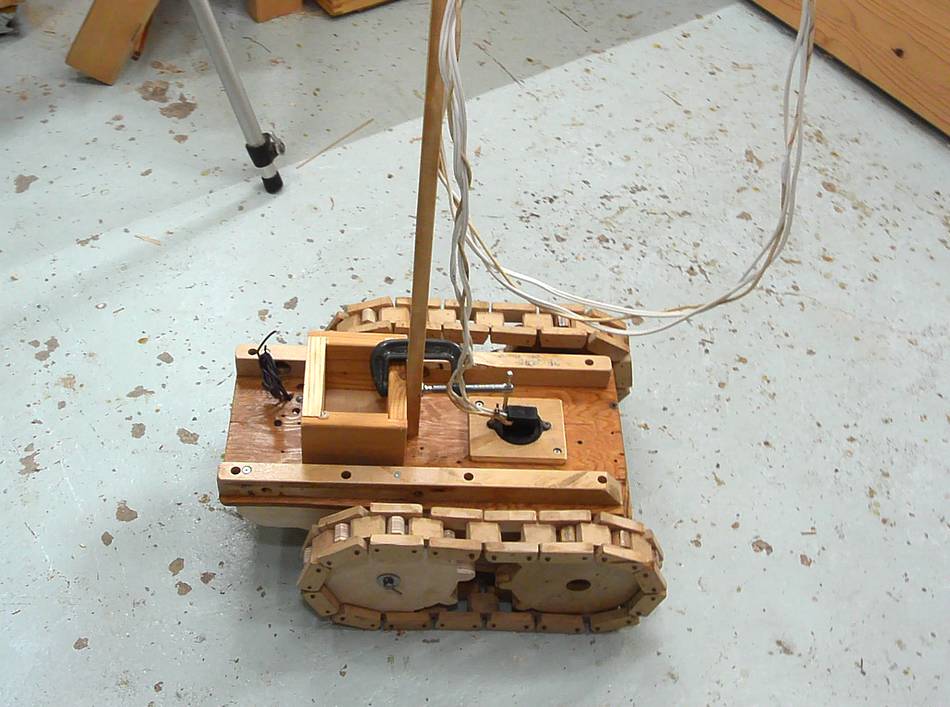
I also temporarily put the old cable mast back on it. The cable mast makes it easier to avoid running over the wires.

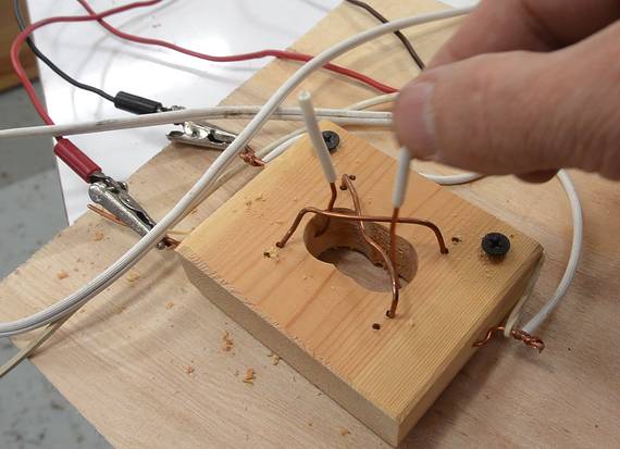 I made two switches to control the tracks out of copper wire. Actually, I'd made
these when I made the videos about
this tracked vehicle in 2008. One side of each motor is always
connected to ground, and the switch will connect the other side to either
+12 volts or -12 volts from a homemade bench top power supply (similar
to this one, but using a variac
instead of a tapped transformer, and with a center tap).
I made two switches to control the tracks out of copper wire. Actually, I'd made
these when I made the videos about
this tracked vehicle in 2008. One side of each motor is always
connected to ground, and the switch will connect the other side to either
+12 volts or -12 volts from a homemade bench top power supply (similar
to this one, but using a variac
instead of a tapped transformer, and with a center tap).
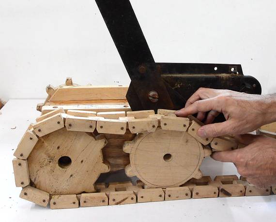
 Testing the drive mechanism in my workshop. It works well on the smooth floor.
 Next, testing it in the backyard. It's barely able to turn in one spot
on the grass. Driving in a curve is much easier. Overall, acceptable,
so I'll keep it with the tracks.
Next, testing it in the backyard. It's barely able to turn in one spot
on the grass. Driving in a curve is much easier. Overall, acceptable,
so I'll keep it with the tracks.
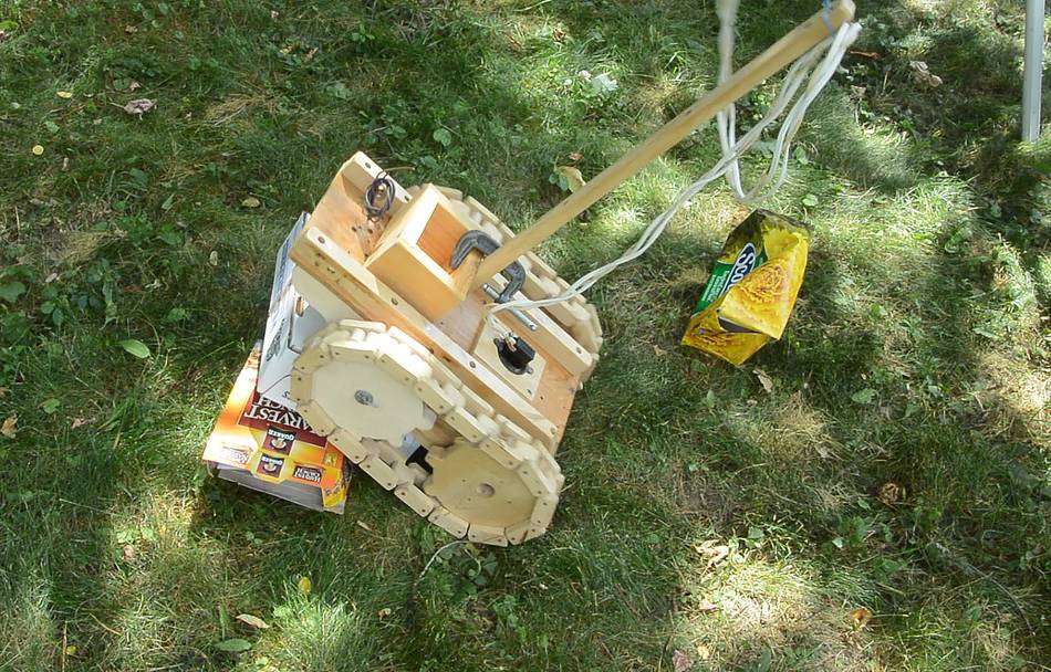 And the tracks are much better at driving over obstacles and terrain than
the wheels and caster were.
And the tracks are much better at driving over obstacles and terrain than
the wheels and caster were.
Next: making the forklift part of this contraption work again.
See also:
 Touring dad's shop attic
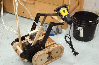 Forklift toy fork lift
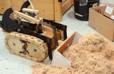 Forklift toy payloader bucket
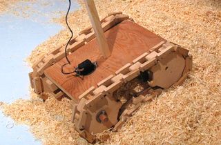 Tank thread tracked vehicle
 Baby soothing machine
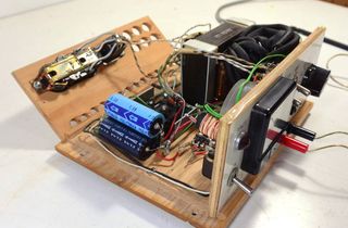 Homemade bench top power supply
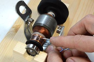 How DC and universal
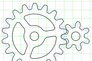 Gear generator program
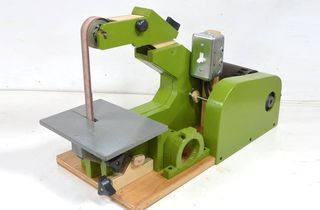 Strip sander
Back to my woodworking website.