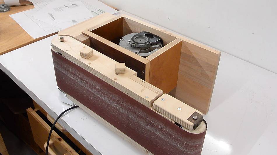
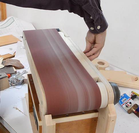
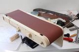
My initial intention had been that to switch between normal mode and edge sander
mode I would turn the sander 180 degrees and then tip it forward. This way what
is normally the front of the belt sander faces up, so that the belt can be
removed and the controls are accessible.
But I realized this meant the belt would move right to left, instead of left to
right like it normally does on edge sanders. More importantly, the
dust collector port would move to the left, which would mean re-routing the
hose every time I flipped it.
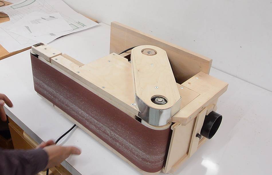
A better arrangement is to simply tip it towards me. But this puts the tension
and tracking controls on the bottom.
If I flip the design of the mechanism, the controls would be on the top in
edge sander mode, and on the back in regular mode, which would be
acceptable.
But the tracking adjustment design I had wasn't very responsive,
so this was ALSO an opportunity to change how that works.
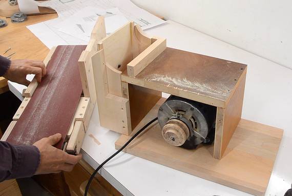
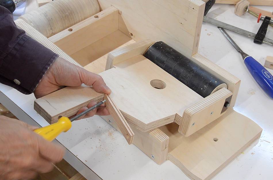
Taking out a few screws, I detached the sander unit from the base.
The problem with my tracking adjust mechanism is that it has a bit of "play" in it
because the tracking screw isn't normally under tension. This means I have to turn
it an extra half a turn if I want to adjust in the other direction. I also have to
overcome the friction in the tensioning lever (which I'm pointing at with my
left hand)
A better design would be to have the tensioner apply the force off-center so the tracking
adjust always has force against it. That way, if the knob is turned only a little
in either direction, the adjustment changes immediately.
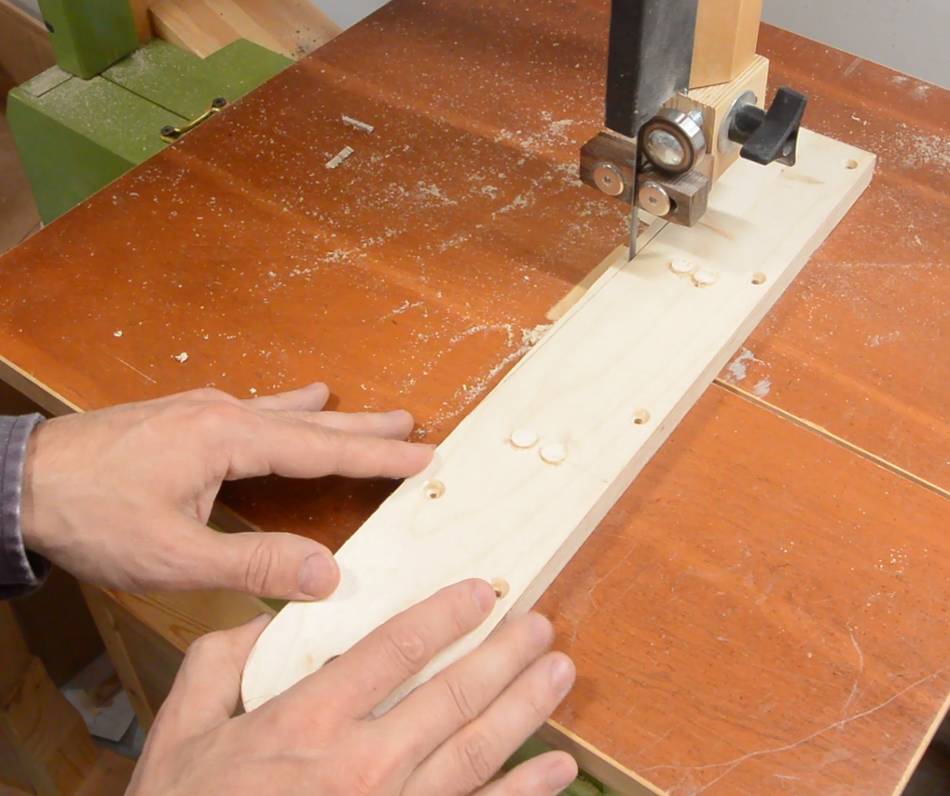
I had to make a new part to hold the idler roller for this, here cutting it out
on the bandsaw.
And screwing on my wooden bearing mounts.
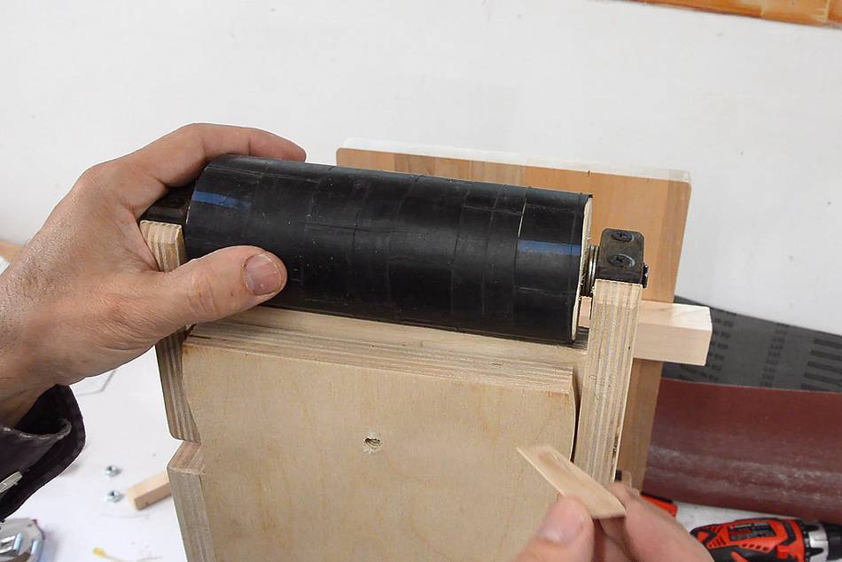
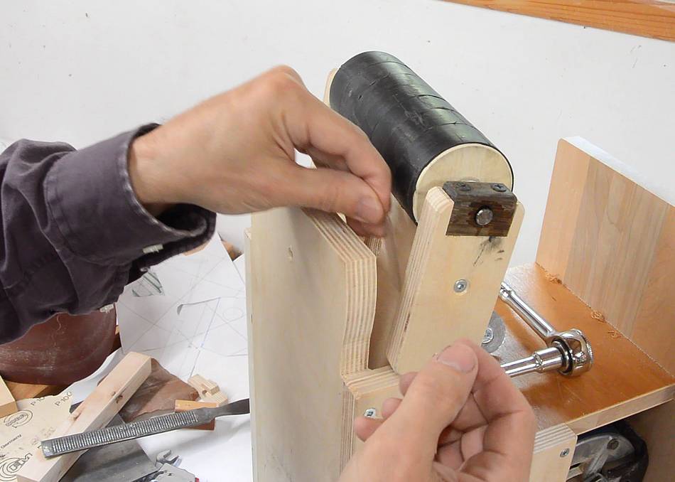
Then, with the new bracket in place, I slid a sanding belt half-way on the
rollers, and pushed the idler roller out as far as I could to establish where
it normally goes. I used a clamp to fix it in place.
The tensioning lever is also a slightly different shape to deal with the angled
load, at right, drilling out the hole for the threaded rod in the new part.
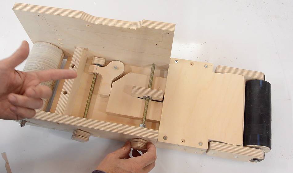
At left, you can see how the new tensioner mechanism works. Tension screw 'T' pulls on
lever 'L' turning it clockwise, which pushes the push rod 'R' against the wooden spring
'S', which is connected to the idler bracket 'B'.
Because the tension load is applied asymmetrically, bracket 'B' will want to rotate
counter clockwise. The tracking adjust knob will go just left of where the bar
clamp is.
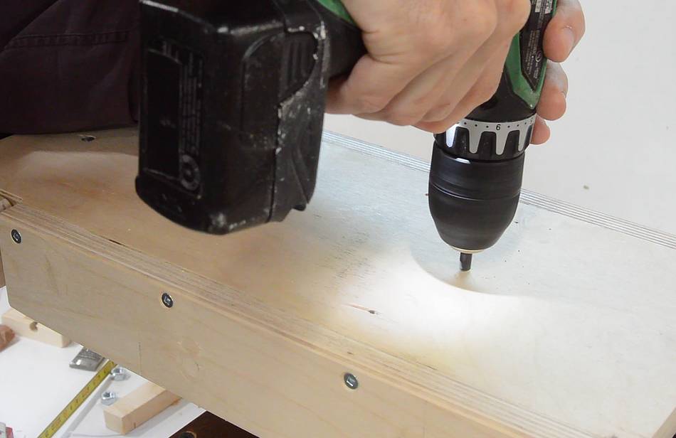
The tracking adjust knob will go through the frame of the sander. Because it needs to
move side-to-side with tension adjustments, I need to make a slot in the frame,
which I'm doing by drilling a series of holes, then squaring out the slot with a rasp.
I also wanted to simplify the design (to make for an easier to build set of plans).
I realized, the plywood layer that holds the bracket isn't really
necessary. It also blocks access to the wooden spring, if that ever needs
servicing. Instead, I can just drill an oversized hole and use a 5/16" bolt and fender
washer to hold the bracket in place.
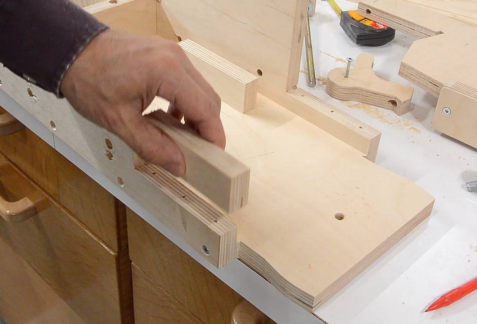
With the plywood layer no longer necessary, the notch where it attached to is now
also redundant, so I'm gluing in pieces of plywood to fill in that notch. This is
mostly to make it look like my improved design.
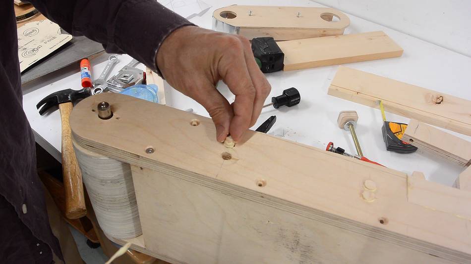
I'm also adding plugs to where the holes for the controls were before. There were
two holes where the knobs were and two extra holes because I first drilled them in the
wrong place.
I then removed the front side and cut it at an angle to follow where the belt normally
goes. This will make it easier to change the belt.
The wooden springs might have a tendency to get pulled out of the slot that they
fit into, so I'm attaching them with a small screw.
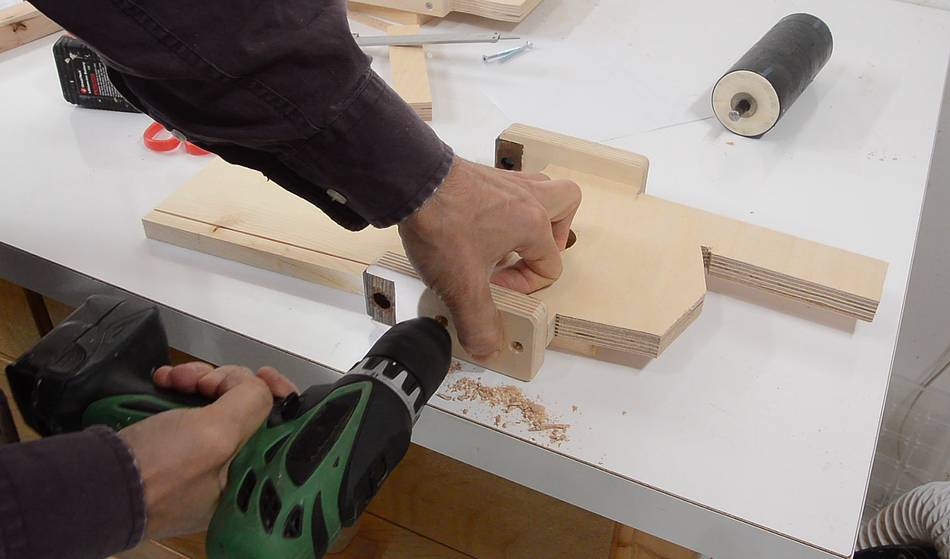
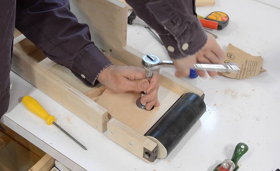
Now attaching the idler bracket with a 5/16" bolt. The bolt screws into a 9/32"
hole in the plywood (about 0.8 mm smaller than the bolt). I just screwed the bolt
straight in the plywood like a wood screw, even though it's a machine screw.
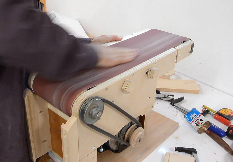
Then installing the belt and playing with the tracking adjustment.
Much more responsive than before, but I had to adjust it quite far from center
to get the belt to track at all.
After getting the belt tracking on center, I pushed it backwards,
and it immediately tracked hard to the right.
If the belt tracks differently forwards than backwards, that indicates
the two shafts for the rollers aren't in the same plane. It's as though the
sander was twisted along its length.
With it tracking hard right going backwards, that suggests that the idler
roller is too high on the right (as seen from here)
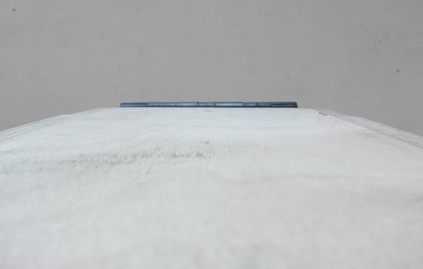
Removing the belt and looking along the sander, the roller did appear
to be slightly higher on the right side, though it seemed well
within reason.
I made a shim out of some veneer and inserted that on the right side to
bring that side down.
But when I tested it again, it appeared that I had way-overcorrected the
misalignment, because now it was tracking badly in the opposite direction.
So I made another shim out of a plastic bottle. This shim is 0.3 mm
thick. The veneer shim I used previously was 0.6 mm thick.
With this shim, tracking was much improved.
I really was surprised that the sander is that sensitive to misaligned
rollers, but then again, the crown I put on the drive roller is very
subtle, so my ability to fix misalignment with tracking adjustment is limited.
And, I guess I also got lucky that my initial build had the two shafts co-planar
probably within about 0.1 mm. But this way of shimming the rollers is a good
way to fix being off by a fraction of a millimeter.
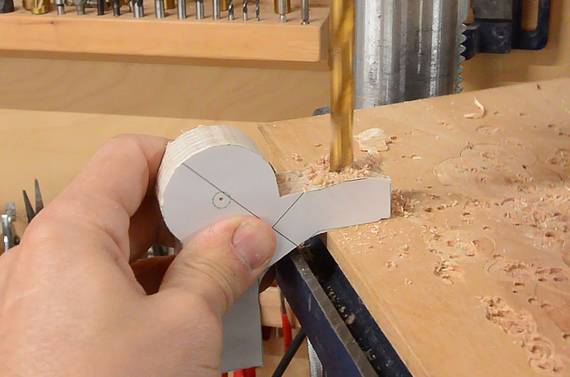
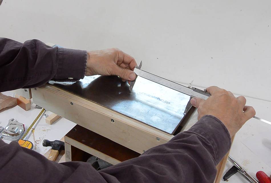
Finally, time to install the metal plate for the platen. Here I'm using my callipers
to scratch where the two mounting holes will be.
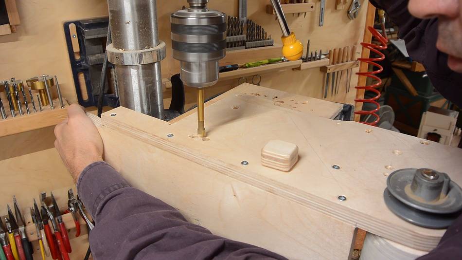
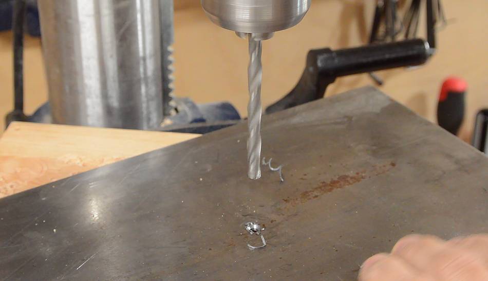
Then drilling a small hole, plus a larger hole part-way to make a countersink for
a #4 wood screw.
Then placing the platen back on the sander and using a center punch to mark the
pilot hole locations.
After drilling the pilot holes, I added a small countersink around the holes because
screws often cause the fibers of the wood near the screw to lift a little bit.
The way the plate is mounted is the same as how I mounted it on my
homemade jointer
Then screwing the platen down. I'm sliding the screwdriver across the screw to make
sure it doesn't protrude.
And with all the alignment issues I had, I also added some metal plates
under the belt. That way, if I accidentally track the belt against the back, it will
rub against these plates instead of cutting into the wood.
 My initial intention had been that to switch between normal mode and edge sander
mode I would turn the sander 180 degrees and then tip it forward. This way what
is normally the front of the belt sander faces up, so that the belt can be
removed and the controls are accessible.
My initial intention had been that to switch between normal mode and edge sander
mode I would turn the sander 180 degrees and then tip it forward. This way what
is normally the front of the belt sander faces up, so that the belt can be
removed and the controls are accessible.


 Belt sander build part 1
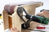 Belt sander build part 2
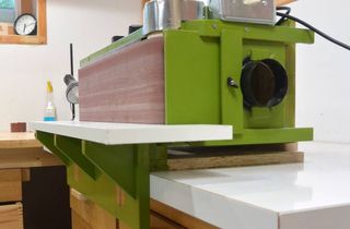 Edge belt sander mode
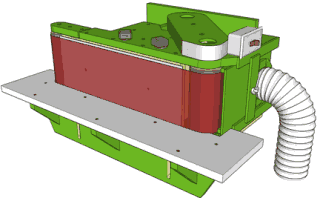 Belt sander plans
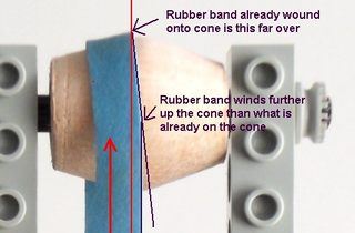 How crowned pulleys keep a belt centered
 More sanding machines
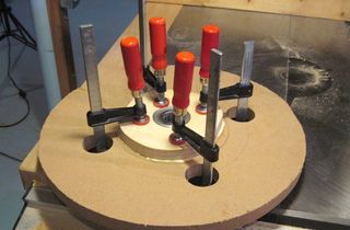 Making bandsaw wheels
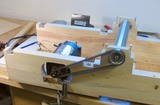 Homemade jointer build