Ever since I built a bandsaw with a larger cut capacity,
I have from time to time been frustrated that the lumber I milled on my bandsaw was too
wide for my 6" jointer. Though wider stock can be flattened with
this trick, a better solution is to get a wider jointer. And the most logical thing
to do to get a wider jointer would be to buy a used one. But I was ready for another challenge,
so I figured I should try to build one.
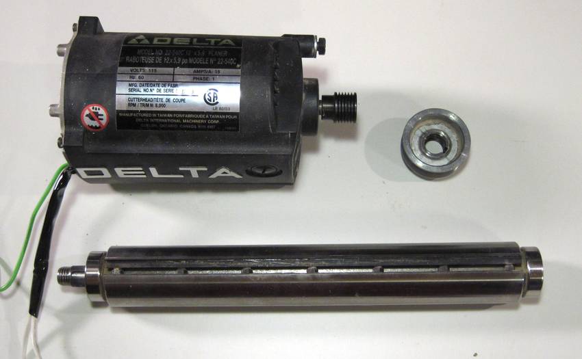
I started by tearing down my Delta planer for parts.
I'd recently bought a slightly better planer on sale for just $200 (+tax)
(see here). So that freed up the old planer to use
as parts for my experiment. Specifically, I wanted to reuse the cutter head, knives, and motor.
The motor is unfortunately a universal motor. This makes
for a small but loud and inefficient motor.
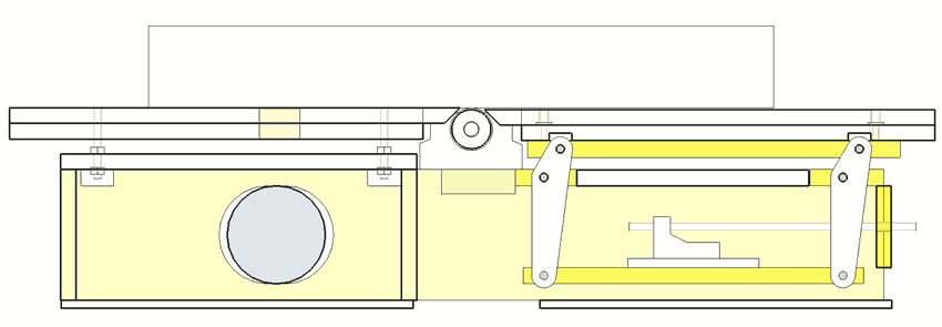
Even though this build was an experiment, I drew it up in CAD, just to figure out how some
of the parts would fit together - assuming it would work at all.
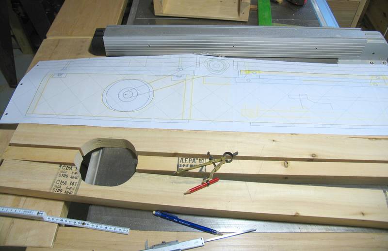
I used my BigPrint program to make some large 1:1 printouts
to work from.
Although I started with lumber wide enough for the sides, I cut it into strips so that
I could alternate the curvature of the growth rings to cut down on potential warping
of the frame from seasonal humidity changes.
The obvious way to mount the cutter head bearings would have been to use pillow blocks.
However, the cutter head already came with pressed-on ball bearings, and these don't have a spherical
housing that could be mounted in a pillow block. It would have been hard to get these off and
mount different bearings. Plus, to get exactly the right kind of bearings and pillow blocks would
have set me back by $70 or more. I'd passed up the opportunity to buy an 8" Inca jointer
for $450, so I figured it would be pretty stupid if I spent a lot trying to build my own.
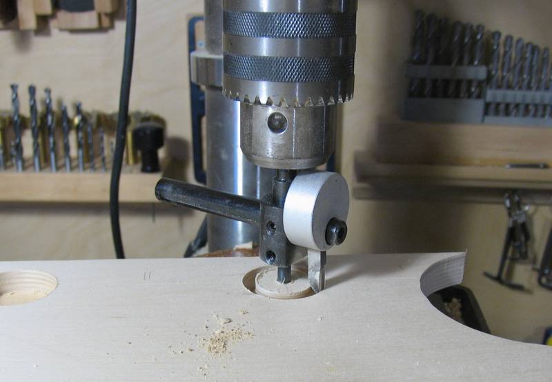
I found a circle cutter at Busy Bee for just $12, so I figured this would be ideal for
cutting perfectly round 40 mm holes for the bearings.
But I found adjusting that circle cutter accurately only marginally less frustrating
than my improvised circle cutter I made when I built my second bandsaw.
I had to cut quite a few test holes before I got it set to produce a tight fit with
the 40 mm diameter bearings.
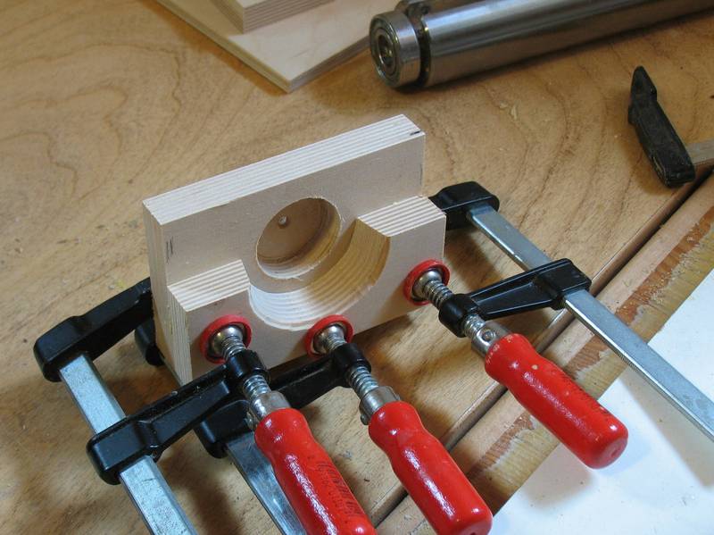
Here's gluing together one of the bearing mounts. The second layer gives it more surface to mount
onto the frame of the jointer.
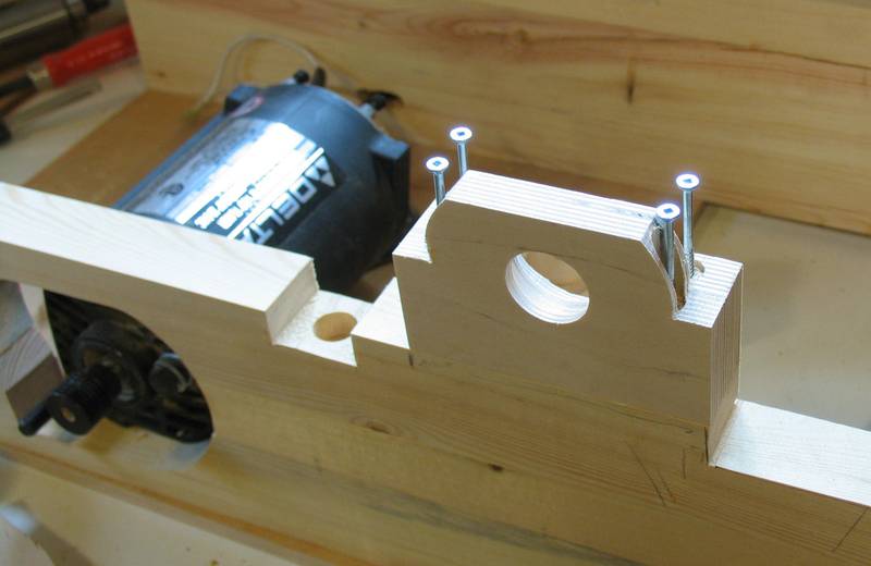
Four long wood screws secure the block to the frame. I was rather paranoid that at some point,
the bearing blocks might let go and that the cutter head would somehow come flying out of the jointer.
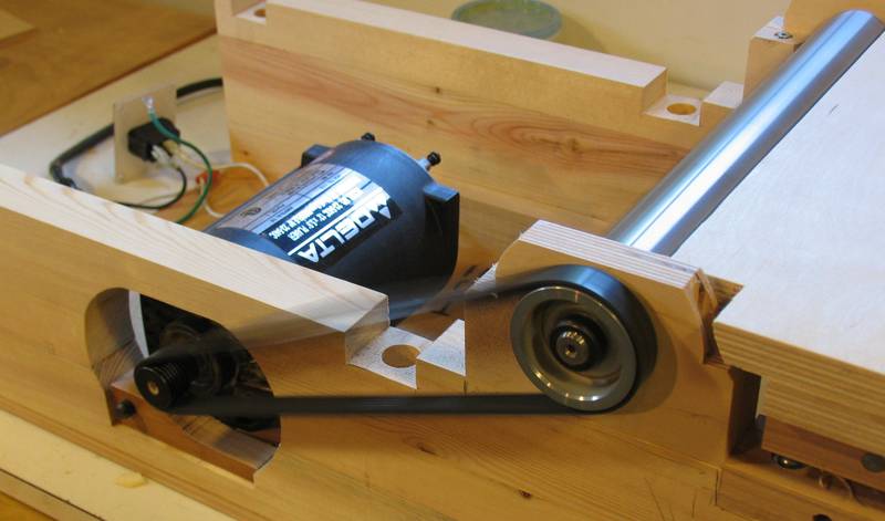
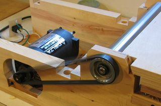
First spin up of the cutter head. It was a bit noisy, but it seems to work.
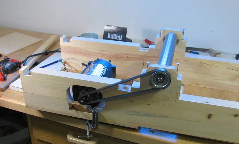
I bought a 27" long (689 mm) serrated belt at a bearing store to replace the short belt that
the planer came with. I need to mount the motor further away from the cutter head to allow
room for shavings to fall down.
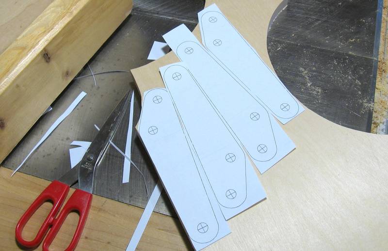
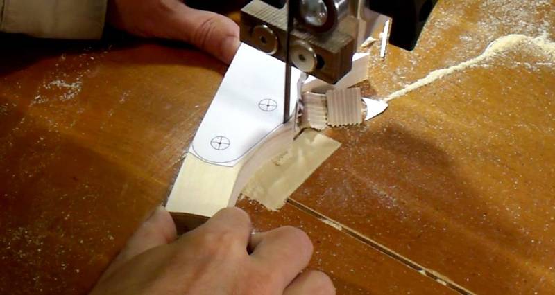
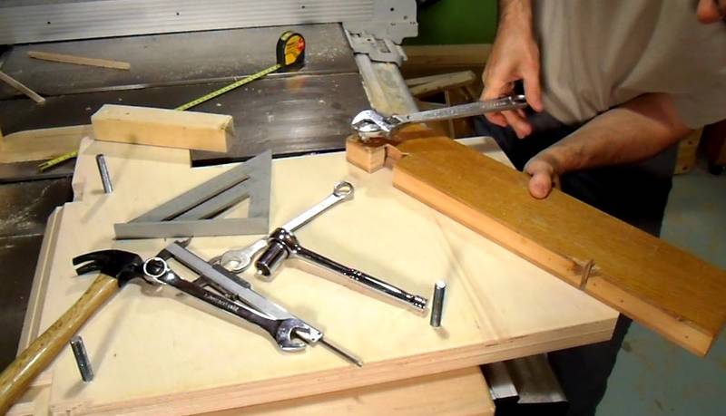
I decided to make a parallelogram mechanism to raise and lower the infeed table. Here's the links for
the mechanism laid out, ready for cutting on the bandsaw.
People often ask me "why don't you use CNC". But with 3/4" thick birch plywood, I'd need a pretty
good CNC machine to come close to the speed and accuracy of a bandsaw. Besides, I
already use a low-cost CNC paper marking machine to make the paper layout.
(also known as an ink jet printer). Ink jet printouts are surprisingly accurate.
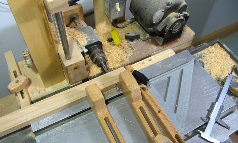
I used my horizontal boring machine to make accurate
holes in some of the straight parts. I used just a regular drill press for the plywood parts -
just making a divot with an awl, then using that pilot hole as a guide for a forstner bit was
quite accurate already.
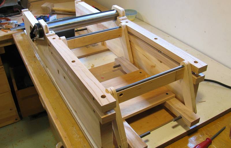
Here's the parallelogram mechanism assembled.
Unlike a typical parallelogram mechanism in most jointers, both links in this mechanism have a longer
arm that extends down, and these are tied together. I figured I'd have more control over it
this way. But it also meant that I had a redundant linkage. Luckily, it all assembled.
If I had been off by even half a millimeter with some of my hole positions, the whole thing would have
been impossible to assemble.
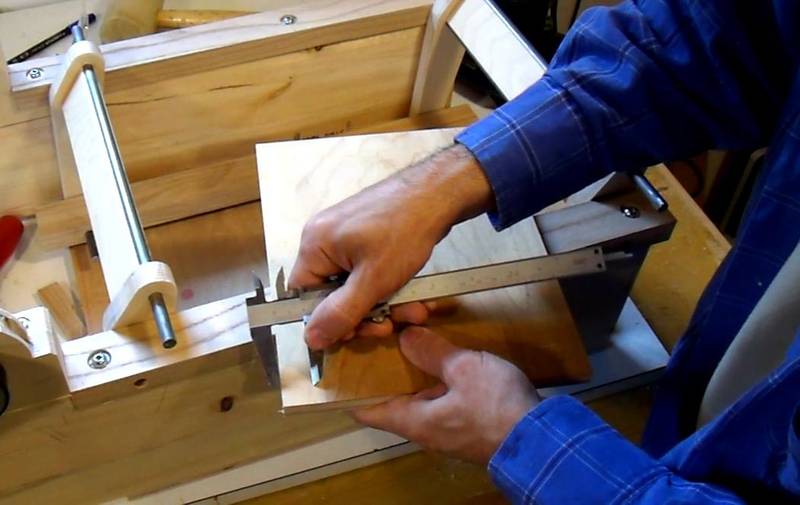
I had been very careful in terms of how I marked everything, usually using my calipers as a
scratching gauge. This method works quite well. But still, in retrospect, I'm surprised the
parallelogram mechanism went together as well as it did. I thought maybe I just got lucky.
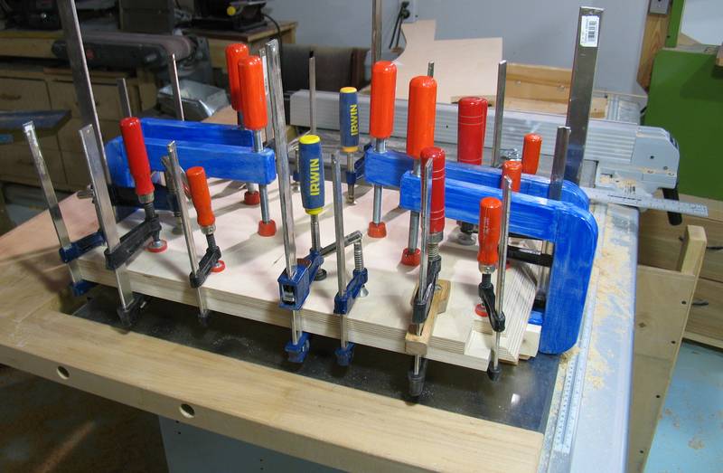
I used two pieces of 3/4" (19 mm) birch plywood laminated together to make the
infeed and outfeed tables.
My long reach C-clamps came in handy for applying pressure
near the middle while gluing these up. I spent a lot of time thinking about different ways of
making the tables, but eventually concluded that plywood was my best option for the size of
table I needed.
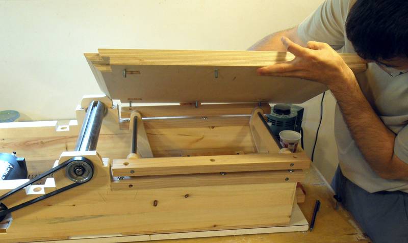
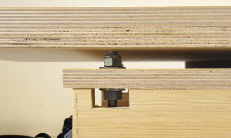
The infeed table mounts to the parallelogram mechanism via some 1/4" (roughly M6) screw studs protruding
out of the underside of the table. The studs are just pieces of machine screw screwed
straight into undersized holes in the plywood.
The table is attached with T-shaped knock-down nuts from the bottom. It's quite fiddly getting
these in. But when I built the parallelogram again I came up
with a better, less fiddly method of attaching the table.
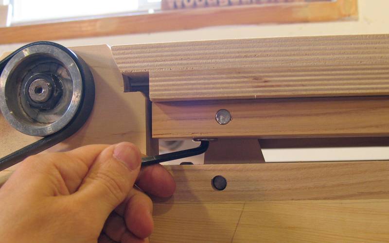
I shortened an Allen key to be able to get in there enough to tighten them.
In retrospect, maybe I should have made the studs longer and just used a regular nut and washer.
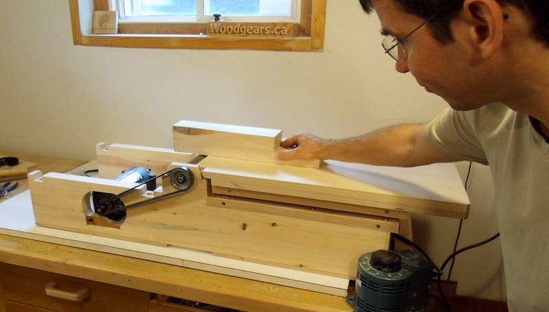
Once the infeed table was mounted, I put the knives back in the cutter head, spun it up,
and pushed a piece of wood part way across the spinning cutter head.
That seemed to work. So far so good.
Up to this point, I had been running the cutter head at less than full speed by reducing
the motor voltage with a variac.
Once I brought the motor up to full speed, I was getting quite a bit of belt vibration
Maybe the rubber belt I bought wasn't rated for that kind of speed.
I should have bought a polyurethane belt instead, like the one that the planer came with,
but that would have cost $20 instead of $10.
With enough belt tension, the vibrations aren't as bad, but it's still noisy.
I'll wait and see if the rubber belt will last.
I used some 7/16" (roughly M10) studs cut from threaded rod to mount the outfeed table.
I almost never adjust the outfeed table on my other jointer,
even when I change knives,
so I figured I didn't need an easy to adjust mechanism for the outfeed table.
I jammed two nuts against each other on the threaded rod and used that to turn the threaded
rod as I screwed it into an undersized hole in the plywood.
I used a board with a 7/16" hole in it as a guide to make sure I'd start the threaded
rod at a right angle to the plywood.
The thread grips the wood well enough that
screwing it straight into the wood was quite sufficient.
Two nuts on the studs clamp around a piece of plywood on the jointer's frame. This makes it possible,
although awkward, to adjust the height on each corner of the table individually.
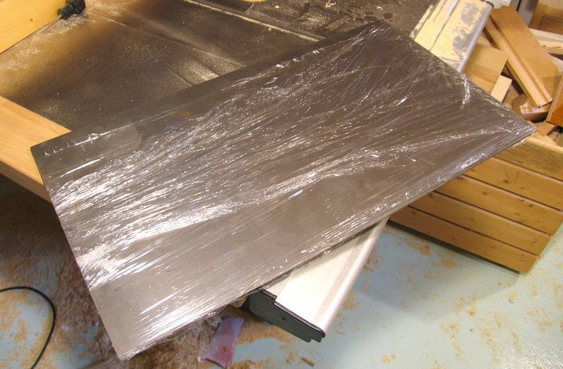
With the jointer working so far, I went ahead and bought the steel plates to put on the tables.
I bought some 11-gauge cold rolled steel, about 3 mm thick.
That steel cost $80 at the Metal Supermarket,
but they also cut it exactly to size for me.
Considering that for the same price, I could get a 5'x5' piece of 3/4" birch ply (1.2m x 1.2m x 19mm),
it makes sense to build machines mostly out of wood.
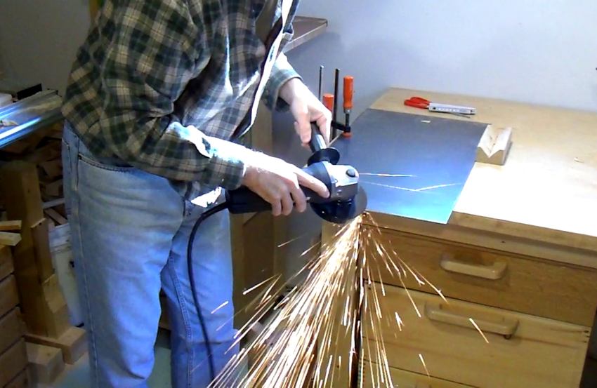
I still had to do some minor work - deburring the edges, beveling the edges nearest the cutter
head, and cutting out the corners to make room for the bearing mounts.
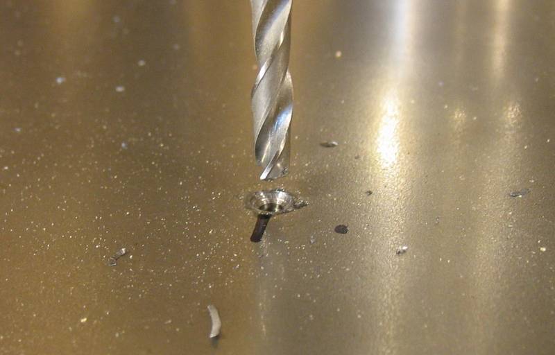
Here's countersinking the screw holes for mounting the plates. I drilled a small through hole,
then used the tip of the larger drill to add a countersink.
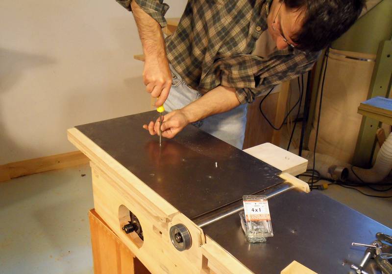
I put the mounting screws in the middle to hold the steel down flat against the plywood,
so recessing the screws from the surface is important.
I only used three #4 screws to hold the plate down. The idea is that the plate "floats"
on the plywood. The plywood provides flatness and rigidity, while the steel provides
a smooth wear-resistant surface. The only reason the steel is as thick as it is because it needs
to overhang the plywood near the cutter head, so it needs to have some rigidity of its own.
Although plywood is very dimensionally stable, I should still expect up to a 0.1%
change in size from humidity changes. So if the steel plates were rigidly attached to the plywood,
that would cause noticeable warping of the tables.
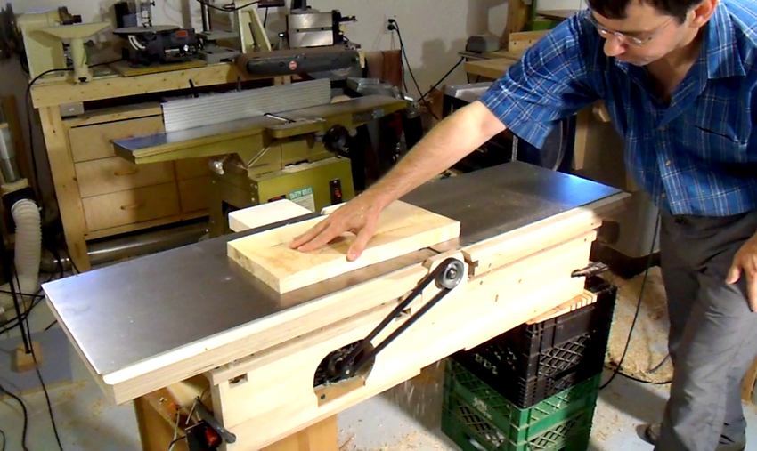
I was very keen to try the jointer out, so even without a fence or guards of any sort,
I had to give it a try!
It did a decent job in this test, even without having tweaked and adjusted everything.
So on with the project...
 I started by tearing down my Delta planer for parts.
I'd recently bought a slightly better planer on sale for just $200 (+tax)
(see here). So that freed up the old planer to use
as parts for my experiment. Specifically, I wanted to reuse the cutter head, knives, and motor.
I started by tearing down my Delta planer for parts.
I'd recently bought a slightly better planer on sale for just $200 (+tax)
(see here). So that freed up the old planer to use
as parts for my experiment. Specifically, I wanted to reuse the cutter head, knives, and motor.


 Hommeade jointer project
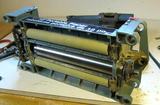 Tearing down the delta planer