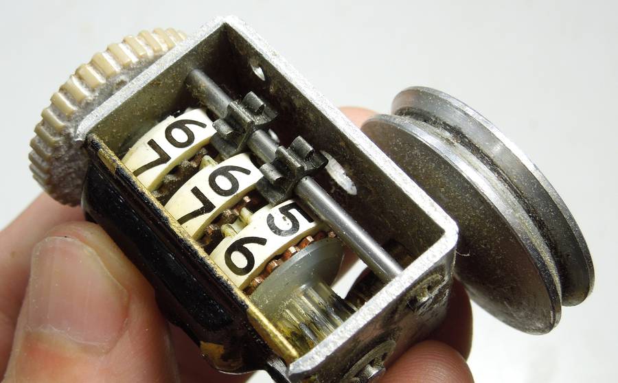
 The key to making these work is a special arrangement of gears, consisting of an
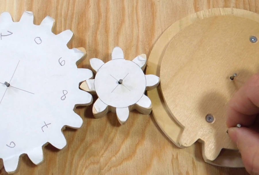
eight-tooth gear which has four teeth missing on one side,
and another "gear" that has all but two teeth missing.
The key to making these work is a special arrangement of gears, consisting of an
eight-tooth gear which has four teeth missing on one side,
and another "gear" that has all but two teeth missing.
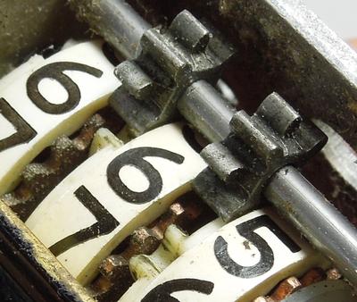
 This gear arrangement performs the "carry" from one digit wheel to the next. When
the two teeth with a notch in between move past the eight-tooth gear, they turn the
eight-tooth gear by two teeth.
This gear arrangement performs the "carry" from one digit wheel to the next. When
the two teeth with a notch in between move past the eight-tooth gear, they turn the
eight-tooth gear by two teeth.
When not being advanced by the two teeth, two of the four teeth on the back of the small eight-tooth gear push against the disk shaped part of the wheel on the right. Only when the notch in the disk comes by can one of the four full width teeth turn through it. This locks the gear's position when it's not being advanced.
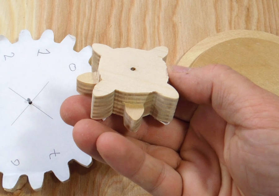
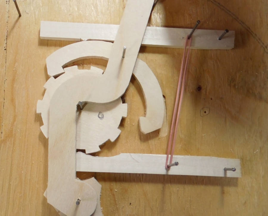 My wooden prototype for the carry gears worked well enough. But I also wanted a way to
increment and decrement the counter value.
My wooden prototype for the carry gears worked well enough. But I also wanted a way to
increment and decrement the counter value.
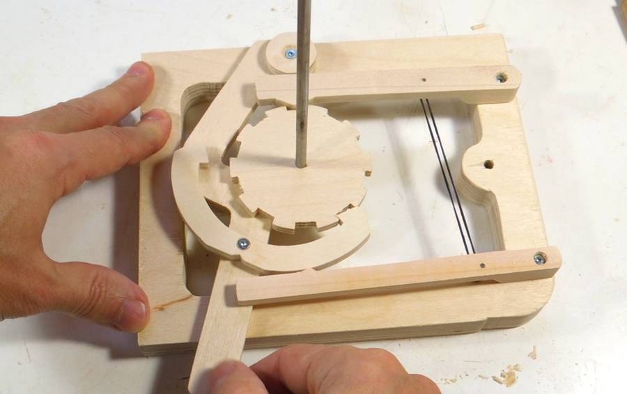
I prototyped a lever/yoke mechanism to ratchet a wheel right or left by one increment when a lever (top to bottom in the photo) is tilted in either direction. This mechanism turned out to be more tricky than carry gears!
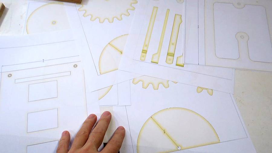 Having prototyped the carry and advance mechanisms, I was confident everything would work,
so I made 1:1 printouts from my SketchUp
CAD model using my
BigPrint program.
Having prototyped the carry and advance mechanisms, I was confident everything would work,
so I made 1:1 printouts from my SketchUp
CAD model using my
BigPrint program.
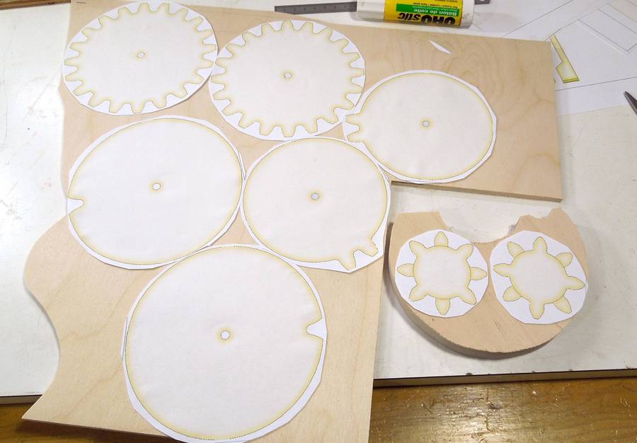 Gear templates arranged to make the best use of my plywood scraps.

 It took 40 minutes to cut all the gears and rotors.
CNC could cut faster,
but if you factor in CNC setup time, the bandsaw still wins.
It took 40 minutes to cut all the gears and rotors.
CNC could cut faster,
but if you factor in CNC setup time, the bandsaw still wins.
 I drilled some slightly oversized holes for a loose fit on the shafts
so that the gears can spin freely.
I drilled some slightly oversized holes for a loose fit on the shafts
so that the gears can spin freely.
 I firmly clamped the 8-tooth gears to my drill press and used large
Forstner bit to partly cut away half the teeth from the eight-tooth gears.
I firmly clamped the 8-tooth gears to my drill press and used large
Forstner bit to partly cut away half the teeth from the eight-tooth gears.
 Cutting out the inside part of the sides of the frame on the scroll saw.
Most of the side is cut away to give a better view of the mechanism.
Cutting out the inside part of the sides of the frame on the scroll saw.
Most of the side is cut away to give a better view of the mechanism.
I could have used a bandsaw to do this, but then I would have had to cut a slot in the side of the frame and then glue it back together.
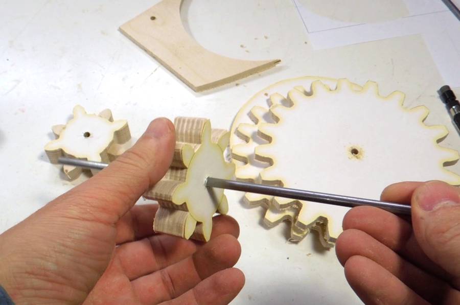
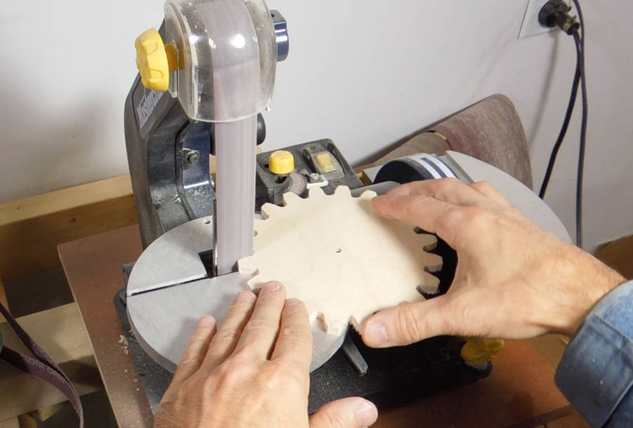 I used a strip sander to tweak the shape of the gears to make
sure they ran smoothly.
I used a strip sander to tweak the shape of the gears to make
sure they ran smoothly.
 Also checking the parts of the carry wheels against the eight-tooth gear, making
sure it will advance without too much friction.
Also checking the parts of the carry wheels against the eight-tooth gear, making
sure it will advance without too much friction.
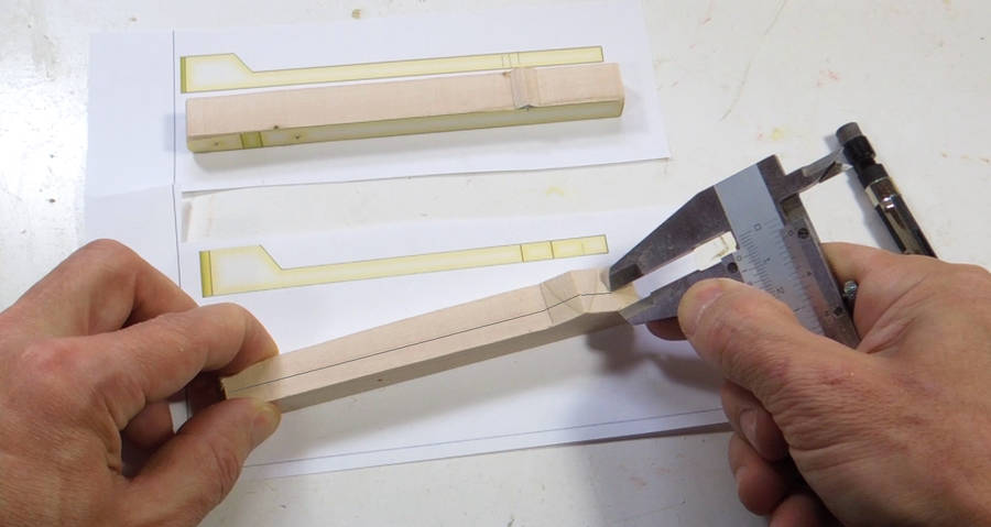 Two levers provide detents (click stops) for the digit wheel and the lever
center. Solid hardwood is ideal for these parts, though I could have made
these from plywood as well. Here's the templates glued onto the wood.
Two levers provide detents (click stops) for the digit wheel and the lever
center. Solid hardwood is ideal for these parts, though I could have made
these from plywood as well. Here's the templates glued onto the wood.
With one face cut, it was easier to transfer the dimensions for the thickness cuts onto what was left than to glue the templates onto the non-flat surface.
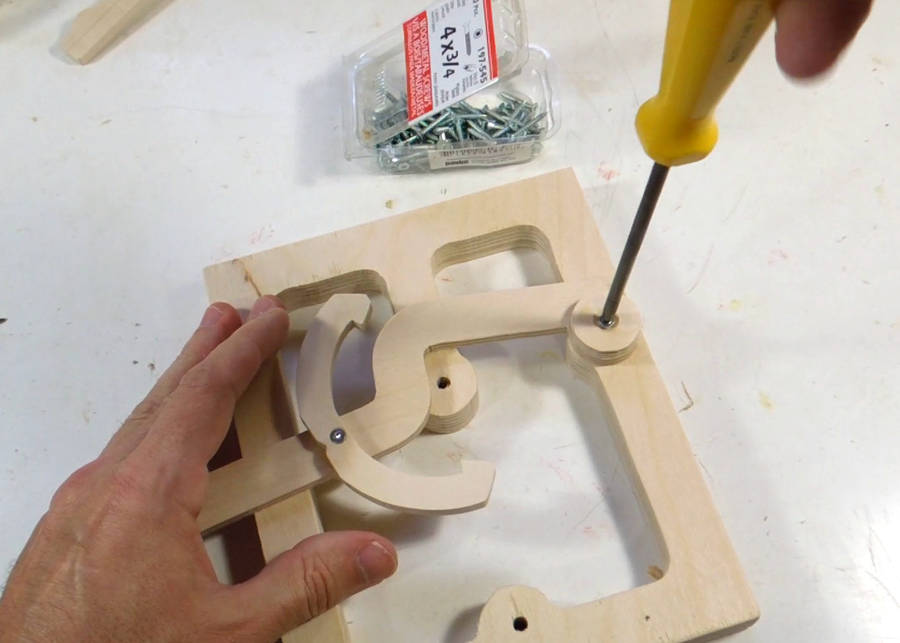 Attaching the lever and yoke to the frame. These pivot on screws. The
screws are not fully tightened to allow movement.
Attaching the lever and yoke to the frame. These pivot on screws. The
screws are not fully tightened to allow movement.
 Detent levers mounted, and testing that the increment/decrement mechanism works.
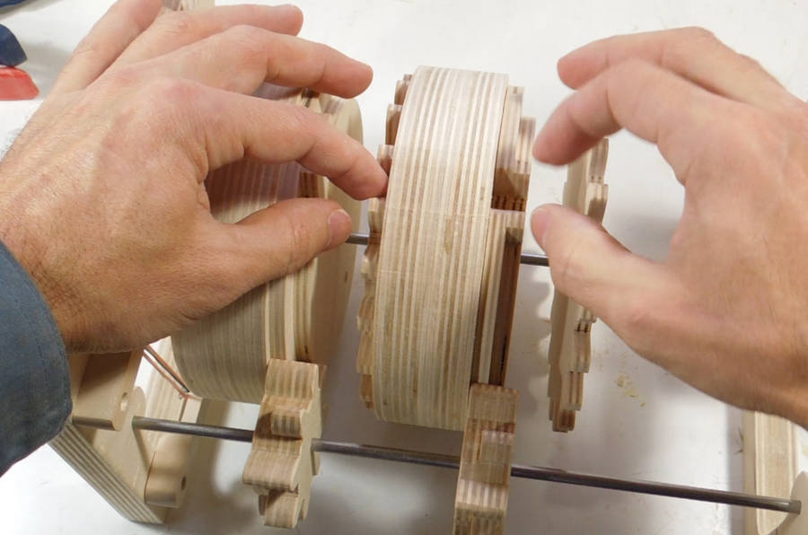 Attaching the gears and carry notches to the sides of the rotors.
Getting the alignment right involves a few tricks (more about that in the
plans and the video).
Attaching the gears and carry notches to the sides of the rotors.
Getting the alignment right involves a few tricks (more about that in the
plans and the video).
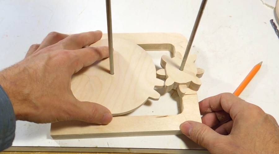
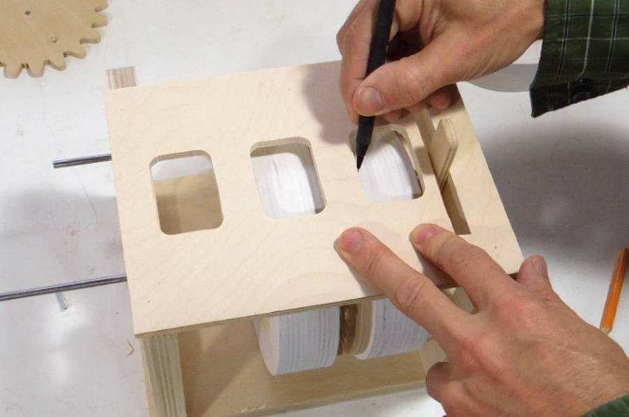 To make sure the numbers will end up in the right place, I assembled
the counter, then increment the right-most wheel by one
click at a time and mark the center of where the digit must go.
The position immediately after the one that also increments
the second rotor is "0". I mark this, along with the next position
as "1", just to make sure I don't get the direction mixed up.
To make sure the numbers will end up in the right place, I assembled
the counter, then increment the right-most wheel by one
click at a time and mark the center of where the digit must go.
The position immediately after the one that also increments
the second rotor is "0". I mark this, along with the next position
as "1", just to make sure I don't get the direction mixed up.
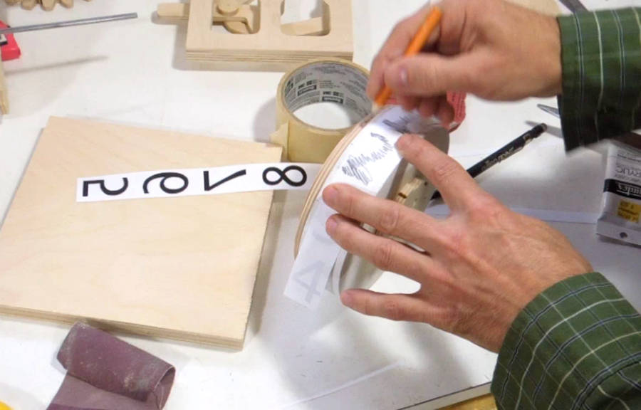 I printed out all the numbers in mirror image (a printable version is included in the
plans), then place them ink side against the rotor,
and rub the back of the printout with a pencil.
This transfers some of the ink onto the rotor.
I printed out all the numbers in mirror image (a printable version is included in the
plans), then place them ink side against the rotor,
and rub the back of the printout with a pencil.
This transfers some of the ink onto the rotor.
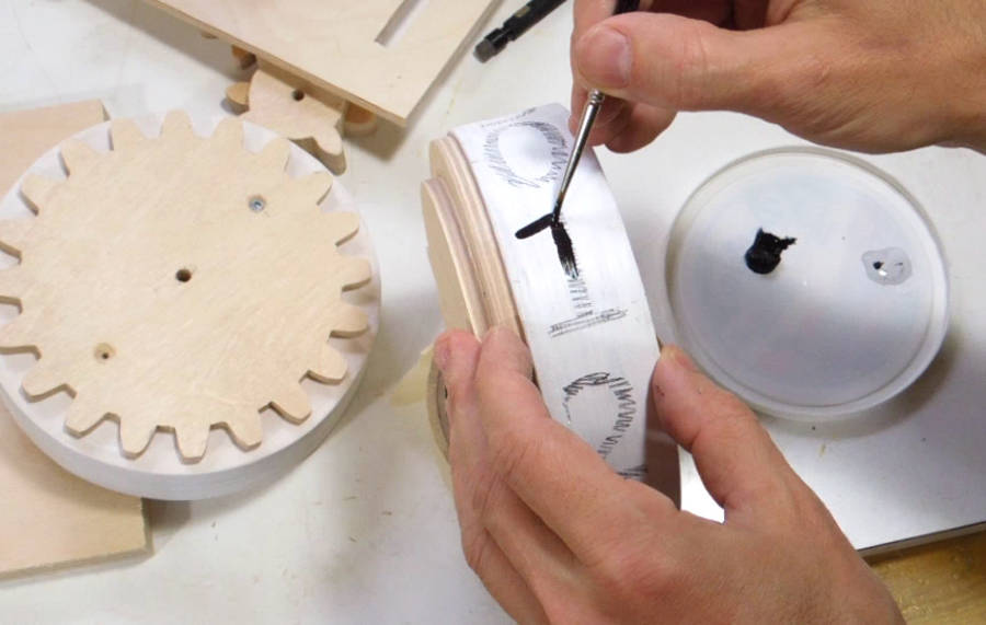 I use acrylic artist paint to paint the digits, using the rubbed through image
as a guide.
I use acrylic artist paint to paint the digits, using the rubbed through image
as a guide.
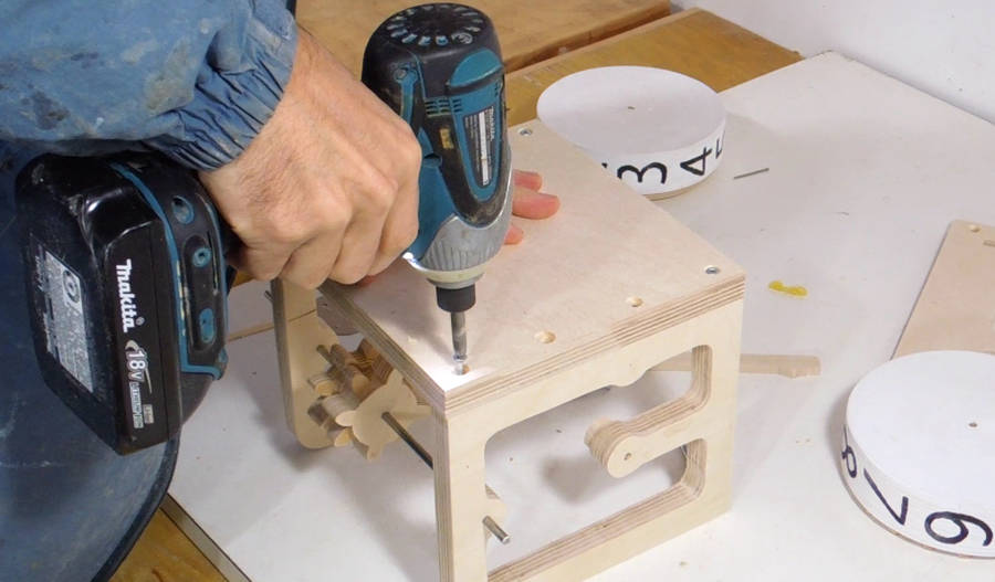 Screwing it together. I'm not using any glue in case I need to tweak
or repair the mechanism later.
Screwing it together. I'm not using any glue in case I need to tweak
or repair the mechanism later.
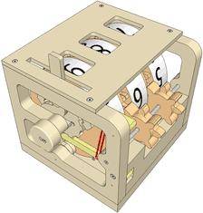
 I like to keep the mechanism as open as possible for better visibility, but for rigidity,
I'm adding a partial back to the enclosure.
I like to keep the mechanism as open as possible for better visibility, but for rigidity,
I'm adding a partial back to the enclosure.
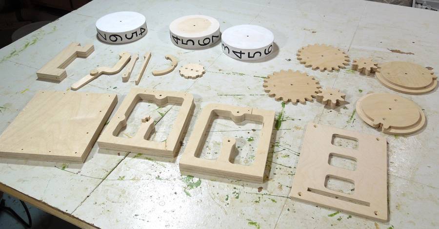 All the parts of the counter laid out for varnishing. Be sure to label where the gear and
notched wheels fit on the rotor, so you can reassemble them exactly the same way.
All the parts of the counter laid out for varnishing. Be sure to label where the gear and
notched wheels fit on the rotor, so you can reassemble them exactly the same way.
 Re-assembling the counter.
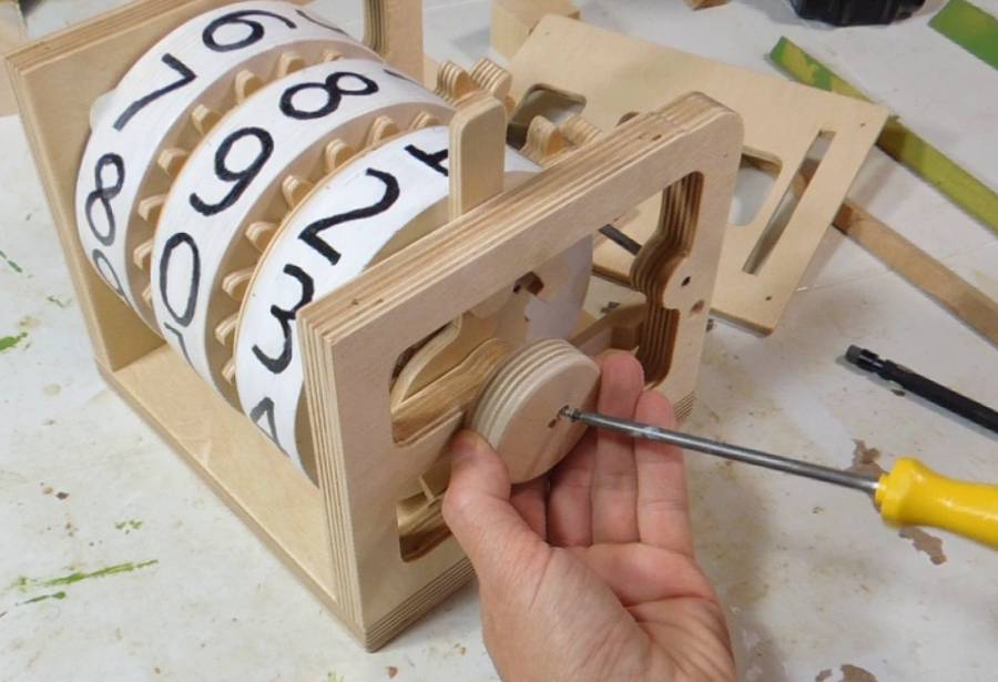 The right-most rotor is locked to the shaft with a setscrew. A knob attached to
the end of the shaft can be used to spin the least significant digit (rightmost rotor)
rapidly by hand. This speeds up turning the counter back to zero after counting.
The right-most rotor is locked to the shaft with a setscrew. A knob attached to
the end of the shaft can be used to spin the least significant digit (rightmost rotor)
rapidly by hand. This speeds up turning the counter back to zero after counting.
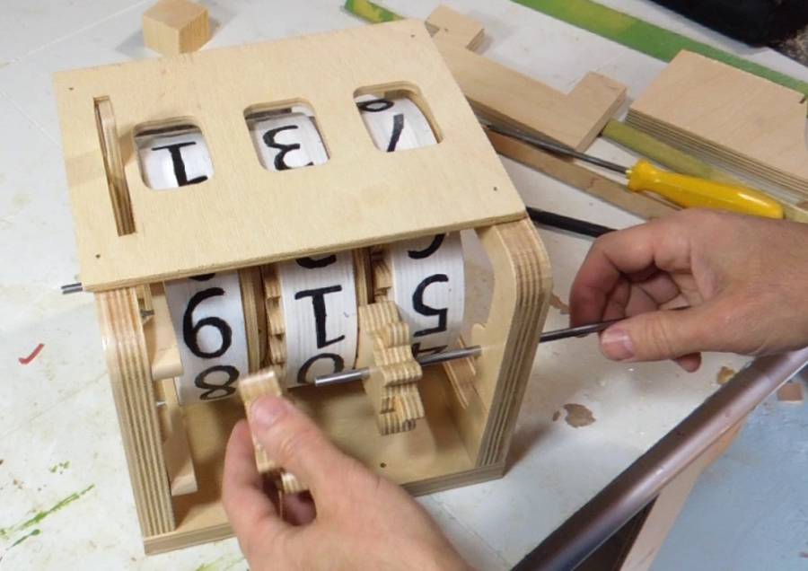
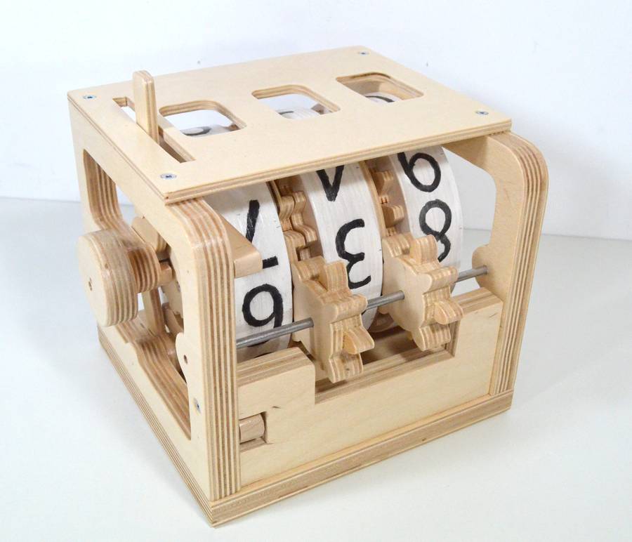
 All assembled, testing the counting functionality. The counter makes a satisfying "thunk"
when the carry gears engage!
All assembled, testing the counting functionality. The counter makes a satisfying "thunk"
when the carry gears engage!
 I also have a detailed set of plans for the counter
available for sale.
I also have a detailed set of plans for the counter
available for sale.
 Ron Walters' 1/2 scale
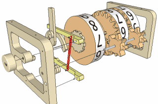 You can buy plans for this counter
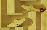 Binary marble adding machine
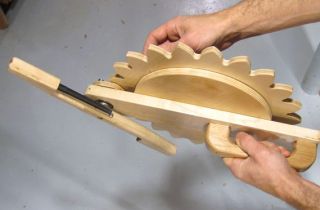 Pen shaking contraption
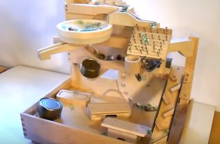 Marble machine 2.1
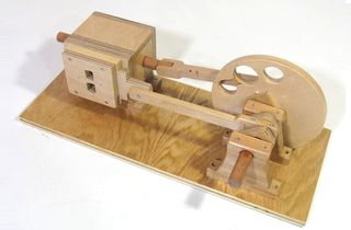 Wooden air engine
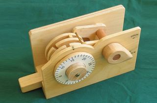 Wooden combination
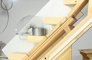 The slinky machine