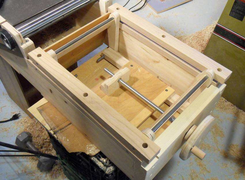
 Up to this point in the construction, I had been moving the infeed table mechanism by hand and using a clamp
to then hold it in place, but I finally added a height adjustment crank.
Up to this point in the construction, I had been moving the infeed table mechanism by hand and using a clamp
to then hold it in place, but I finally added a height adjustment crank.
Up to this point in the construction, I had been moving the infeed table mechanism by hand and using a clamp
to then hold it in place, but I finally added a height adjustment crank.
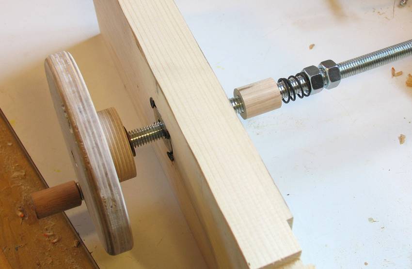 The crank is attached to a piece of 3/8" threaded rod, which goes through a large washer
attached to the outside case with four drywall screws. Two small washers behind the
crank allow it to turn smoothly against the large washer.
On the other side, a spacer, spring, and two nuts locked to each other push against the washer.
I hadn't planned on the spacer, but without it, the nuts would have ended up inside
the piece of enclosure, and I wouldn't have been able to get a wrench around them.
The crank is attached to a piece of 3/8" threaded rod, which goes through a large washer
attached to the outside case with four drywall screws. Two small washers behind the
crank allow it to turn smoothly against the large washer.
On the other side, a spacer, spring, and two nuts locked to each other push against the washer.
I hadn't planned on the spacer, but without it, the nuts would have ended up inside
the piece of enclosure, and I wouldn't have been able to get a wrench around them.
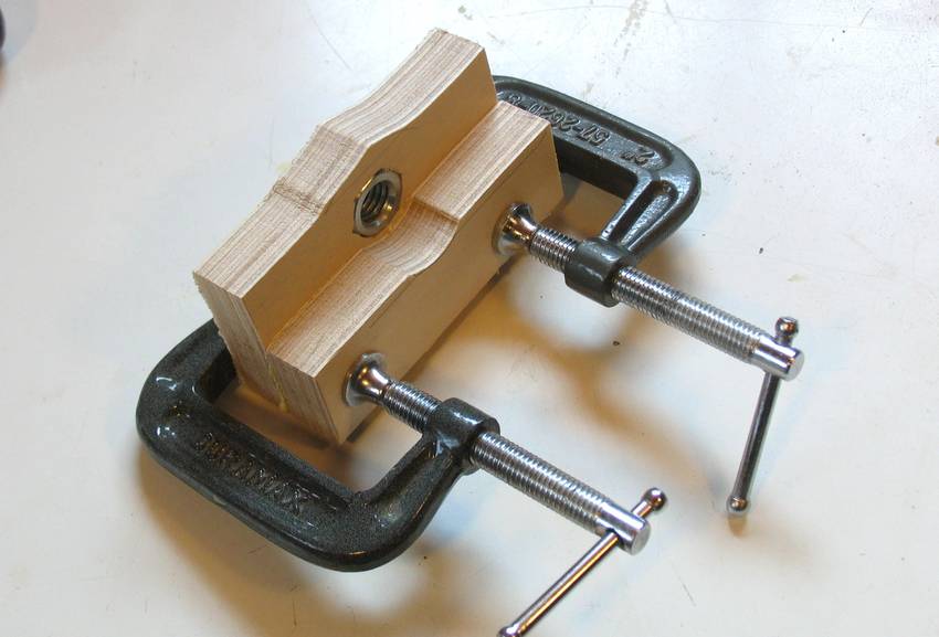 The other end of the threaded rod goes through a nut mounted in a block of wood.
The nut is just pressed into a hole slightly too small for the nut - I squished
it in there with a vise. That block is attached
to a piece of plywood that is screwed to the bottom of the links.
The other end of the threaded rod goes through a nut mounted in a block of wood.
The nut is just pressed into a hole slightly too small for the nut - I squished
it in there with a vise. That block is attached
to a piece of plywood that is screwed to the bottom of the links.
The mechanism works pretty smoothly, although it takes about ten turns to lower the table by two millimeters.
 I never used the blade guard on my 6" jointer, but I figured for this jointer, a guard would be
a good idea. I wasn't so much afraid that I'd get my hands in the cutter head as I was
afraid of the cutter head, or some part of it, somehow jumping out of the
jointer and coming flying at me. After all, this is an unproven machine.
I never used the blade guard on my 6" jointer, but I figured for this jointer, a guard would be
a good idea. I wasn't so much afraid that I'd get my hands in the cutter head as I was
afraid of the cutter head, or some part of it, somehow jumping out of the
jointer and coming flying at me. After all, this is an unproven machine.
I cut out a piece of paper to figure out a shape that would work for the guard.

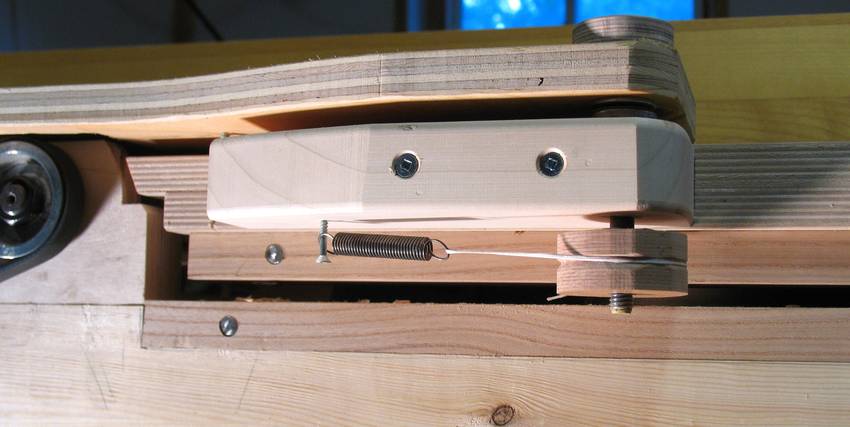
I should use a bigger spring, but that small spring was the most suitable one I had lying
around, and it seems to do the job.
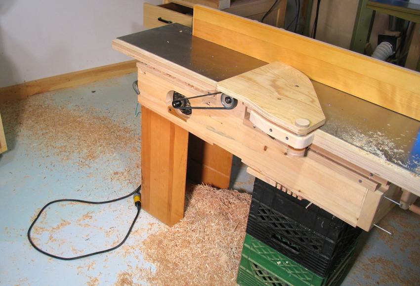
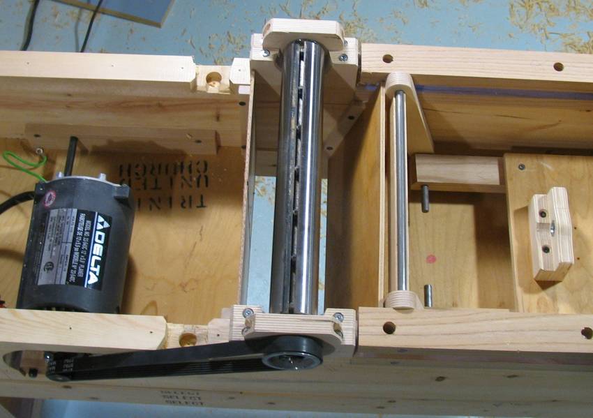
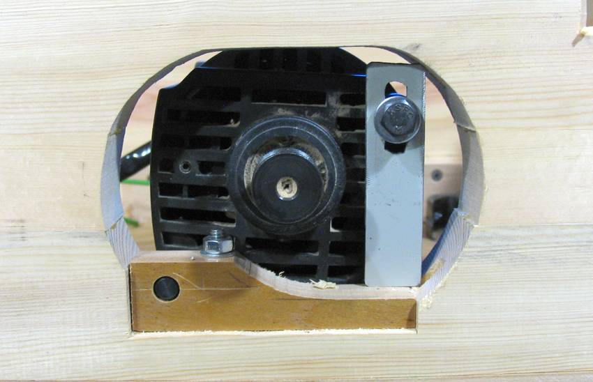 In the planer, the motor was mounted to pivot on the shaft (bottom left in the image), with another bolt to
lock the pivoting for belt tensioning. I wanted to come up with a mechanism where tightening a screw would
tighten the belt, but in the end, I couldn't think of anything that would fit in the constrained space, so
I just took a piece of aluminium and cut a slot in it. The motor is tensioned by hand, then the bolt tightened
to lock the position. The strip of metal isn't attached to anything, it just pushes against the bottom
of the opening.
In the planer, the motor was mounted to pivot on the shaft (bottom left in the image), with another bolt to
lock the pivoting for belt tensioning. I wanted to come up with a mechanism where tightening a screw would
tighten the belt, but in the end, I couldn't think of anything that would fit in the constrained space, so
I just took a piece of aluminium and cut a slot in it. The motor is tensioned by hand, then the bolt tightened
to lock the position. The strip of metal isn't attached to anything, it just pushes against the bottom
of the opening.
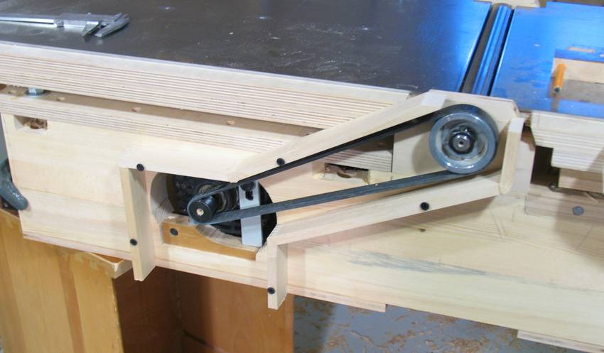 I made some pieces of wood to fit around the belt for a guard. The pieces are strips of maple, 1 cm thick,
joined at the corners with finger joints made with my
screw advance box joint jig. Here are the pieces of the housing screwed to the jointer frame.
I made some pieces of wood to fit around the belt for a guard. The pieces are strips of maple, 1 cm thick,
joined at the corners with finger joints made with my
screw advance box joint jig. Here are the pieces of the housing screwed to the jointer frame.
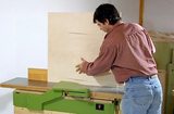
I wanted to make a piece of plywood that would fit exactly over this shape. Normally, one would just put the plywood against it and trace around it with a pencil, but if I put a piece of plywood against it, there wouldn't be enough room behind it to trace the outline. What to do?
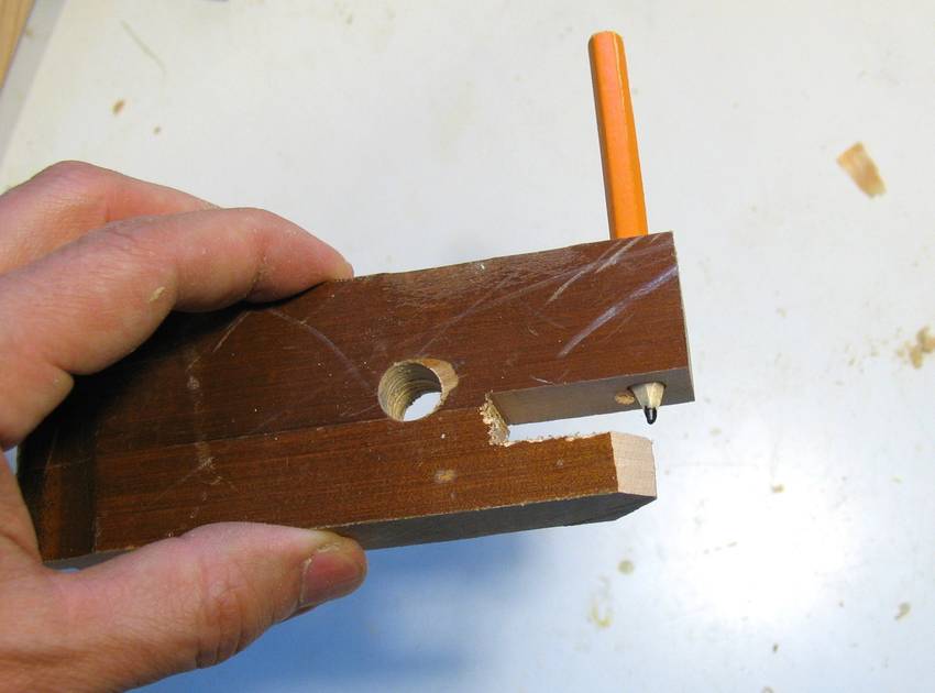 Time for another little invention! This is the marking tool I came up with for marking the outline
on the front of the plywood while tracing the shape at the back. The bottom leg of the wood
traces against the outline of the enclosure while the pencil draws on the front.
Time for another little invention! This is the marking tool I came up with for marking the outline
on the front of the plywood while tracing the shape at the back. The bottom leg of the wood
traces against the outline of the enclosure while the pencil draws on the front.
 Here's using that gauge. I was pretty happy with this trick, but I have to admit, I couldn't
think of any other time such a marking gauge would have been useful. Maybe it wasn't such
a great invention after all.
Here's using that gauge. I was pretty happy with this trick, but I have to admit, I couldn't
think of any other time such a marking gauge would have been useful. Maybe it wasn't such
a great invention after all.
 With the outline traced, I cut out the cover, unscrewed the guard parts from the jointer,
and glued it all together.
With the outline traced, I cut out the cover, unscrewed the guard parts from the jointer,
and glued it all together.
After the glue dried, I flipped it over and drilled the screw holes in the strips of maple all the way through to the front.
 The guard mounted. I had to leave it open at the top - otherwise, it would hit the guard that
swings over the cutter head.
But that's OK. That part is normally covered by the blade guard.
The guard mounted. I had to leave it open at the top - otherwise, it would hit the guard that
swings over the cutter head.
But that's OK. That part is normally covered by the blade guard.
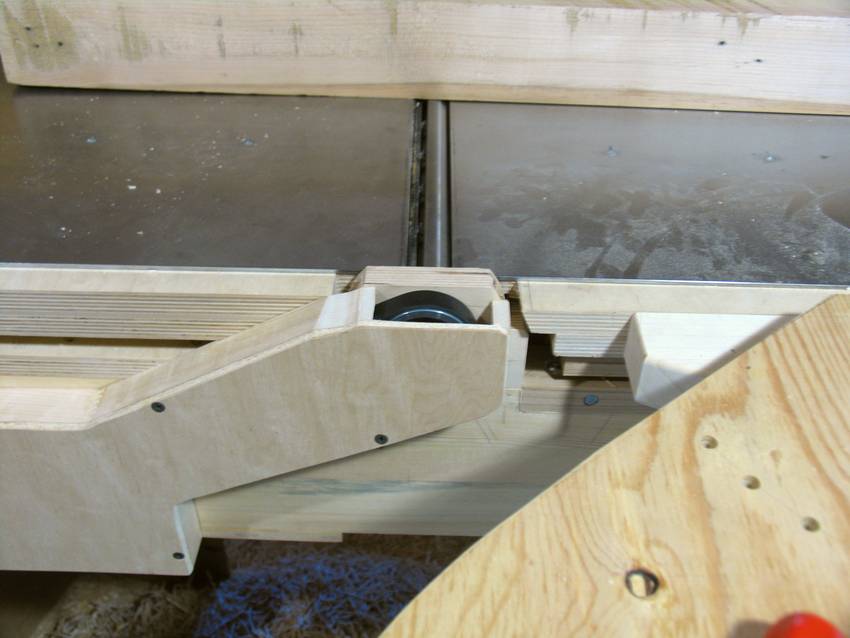
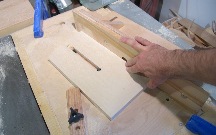 Here's milling the slot for my fence attachment bracket.
I'm using two of my blue long-reach C clamps as stops on either end, plus the non fingered end of a fingerboard to press the workpiece against the fence. I don't feel entirely safe using a router table like this, so I wanted to make sure my workpiece was constrained.
I milled the slot in about five passes of increasing depth, this photo was taken partway through the last pass.
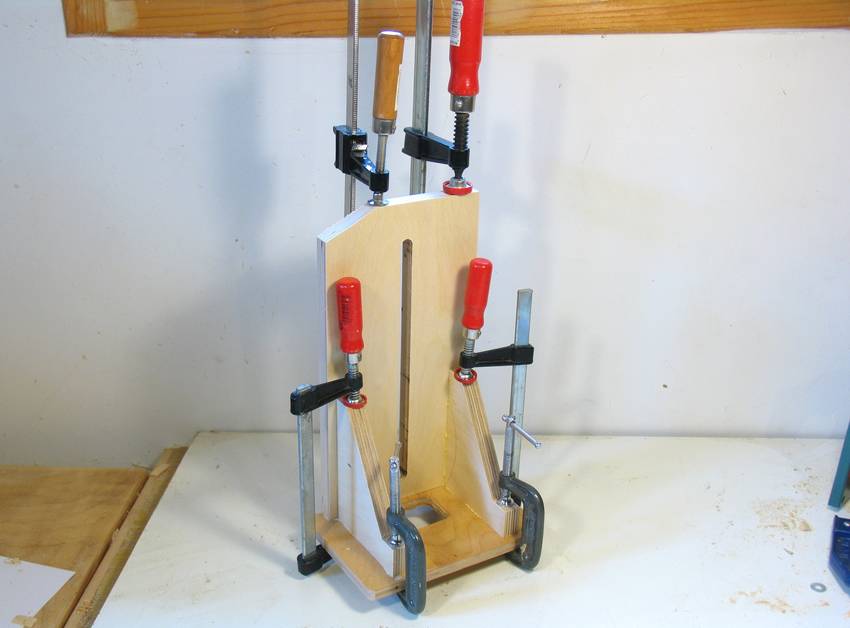 Gluing the fence support together.
The fence is a fixed 90 degrees, no bevel capability. I don't use my jointer for bevel cuts, so I figure it's better to have a fence that is always at 90 degrees than to have one that can be misadjusted.
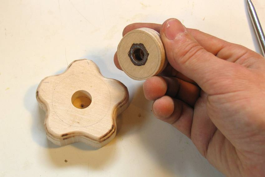 And a nice locking knob. This one's made out of two pieces, glued together, with a nut pressed into
one piece. The hole with the nut on it is smaller on the other side, and gluing the pieces together
makes a T-shaped knob with the nut captive.
And a nice locking knob. This one's made out of two pieces, glued together, with a nut pressed into
one piece. The hole with the nut on it is smaller on the other side, and gluing the pieces together
makes a T-shaped knob with the nut captive.
 All along, as soon as I could, I did lots of testing of this jointer.
Two milk crates and an old drawer serve as a temporary stand.
All along, as soon as I could, I did lots of testing of this jointer.
Two milk crates and an old drawer serve as a temporary stand.
Shavings were coming out the bottom, but they were also blown all around the inside of the jointer, and out the outfeed side. I knew I'd have to make some internal baffles to direct the shavings down, but it sure was odd seeing shavings come flying out the front. I think the wind from the motor may have had something to do with it.
 So here's two thin scraps of plywood mounted around the cutter head to direct the shavings down.
 I first mounted the knives using the knife setting gauge that came with my thickness planer.
But during testing, I found that this jointer had a bit of a howl to it.
Not that it mattered much given how
loud the brush motor is, but still bothersome. My 6" jointer has hardly any howl at all.
Checking things out,
I realized the knives on my 6" jointer only protruded by about .030 (.75 mm) out of the
cutter head, whereas on this cutter head, the knives protruded by .060 (1.5 mm).
I figured a smaller protrusion would make less noise. There would also be less danger of
kickback with a smaller amount of protrusion.
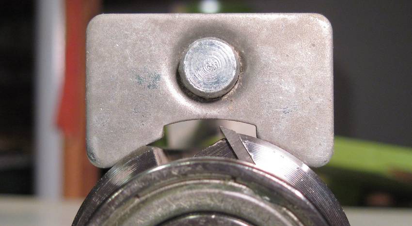
So I decided to set the knives deeper. The photo at left
shows how I set the knives, vs the height that the setting gauge would set them at.
I first mounted the knives using the knife setting gauge that came with my thickness planer.
But during testing, I found that this jointer had a bit of a howl to it.
Not that it mattered much given how
loud the brush motor is, but still bothersome. My 6" jointer has hardly any howl at all.
Checking things out,
I realized the knives on my 6" jointer only protruded by about .030 (.75 mm) out of the
cutter head, whereas on this cutter head, the knives protruded by .060 (1.5 mm).
I figured a smaller protrusion would make less noise. There would also be less danger of
kickback with a smaller amount of protrusion.
So I decided to set the knives deeper. The photo at left
shows how I set the knives, vs the height that the setting gauge would set them at.
 I couldn't move the tables far enough out of the way to use that knife setting gauge anyway,
so I figured the thing to do was to set the knives to the outfeed table like I always
do on my other jointer, but to have them project only .025" past the cutter head.
I couldn't move the tables far enough out of the way to use that knife setting gauge anyway,
so I figured the thing to do was to set the knives to the outfeed table like I always
do on my other jointer, but to have them project only .025" past the cutter head.
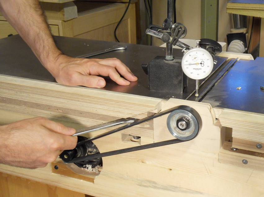
But before setting the knives to the outfeed table, I had to make sure the outfeed table was parallel to the cutter head and exactly .025" above it. Here I'm using a dial indicator to check the outfeed table as I'm adjusting it.
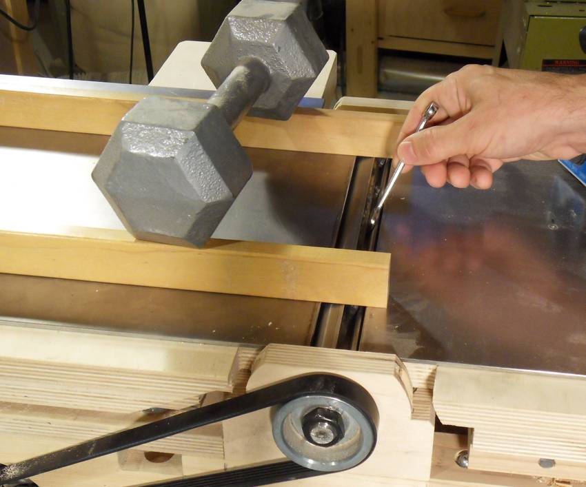 The cutter head is one of those with springs that push the knives up, so there are no
adjustment screws. I used two smooth straight pieces of hardwood pressed down on
the outfeed table as a stop to set the knives against.
I made sure the head was rotated so that the knife was at top dead center, then
pushed them down with the wood and the weight.
After that, it was just a matter of tightening the screws.
The cutter head is one of those with springs that push the knives up, so there are no
adjustment screws. I used two smooth straight pieces of hardwood pressed down on
the outfeed table as a stop to set the knives against.
I made sure the head was rotated so that the knife was at top dead center, then
pushed them down with the wood and the weight.
After that, it was just a matter of tightening the screws.
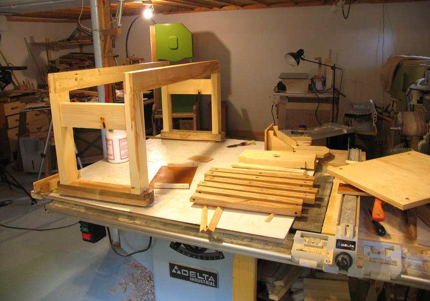
 I also built a stand for the jointer. Unlike a typical jointer stand, this one has the legs
far apart.
That way, shavings can pile up in the middle. On my other jointer, the dust chute often plugs up, and
it really doesn't take long for the shavings heap to get up to the chute exit. So I wanted to make
sure there was room for a big pile of shavings under this one.
I also built a stand for the jointer. Unlike a typical jointer stand, this one has the legs
far apart.
That way, shavings can pile up in the middle. On my other jointer, the dust chute often plugs up, and
it really doesn't take long for the shavings heap to get up to the chute exit. So I wanted to make
sure there was room for a big pile of shavings under this one.
Then did lots of testing. I went through all my lumber, straightening anything that was curved, and smoothing anything that was rough!
 With the jointer working and tested, it was time to take it all apart again
for varnishing and painting.
With the jointer working and tested, it was time to take it all apart again
for varnishing and painting.
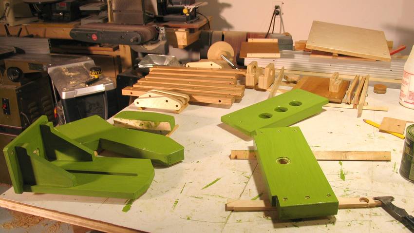 I still had the paint
that I originally bought for my first homemade bandsaw.
Maybe I should try a different colour - the blue on
Fernand's bandsaw
or Dejan's bandsaw turned out quite nice. But I was
keen on getting this jointer done, so green again it was!
I still had the paint
that I originally bought for my first homemade bandsaw.
Maybe I should try a different colour - the blue on
Fernand's bandsaw
or Dejan's bandsaw turned out quite nice. But I was
keen on getting this jointer done, so green again it was!
For the painted part, I started with one coat of clear water-based Varathane, then the paint, and then another coat of Varathane to protect the paint and give it a bit of a shine. The parts that didn't get the green paint got three coats of water-based Varathane.
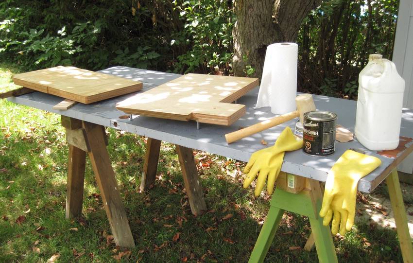 I used an oil-based varnish on the infeed and outfeed tables.
With the top of the tables covered in metal, I was concerned that with humidity changes, the bottom of the tables would absorb or release moisture more quickly than the top. This could lead to uneven moisture gradient in the wood, which would lead to an uneven expansion and a slight bowing of the tables.
To my knowledge, oil based varnishes are less vapour permeable than water based ones, so that should mitigate the problem. I applied three coats to all sides of the tables. I did that in my back yard -- too smelly to do inside. Fortunately, with a hot and windy weather, it dried fast enough that I was able to do put on three coats in one day.
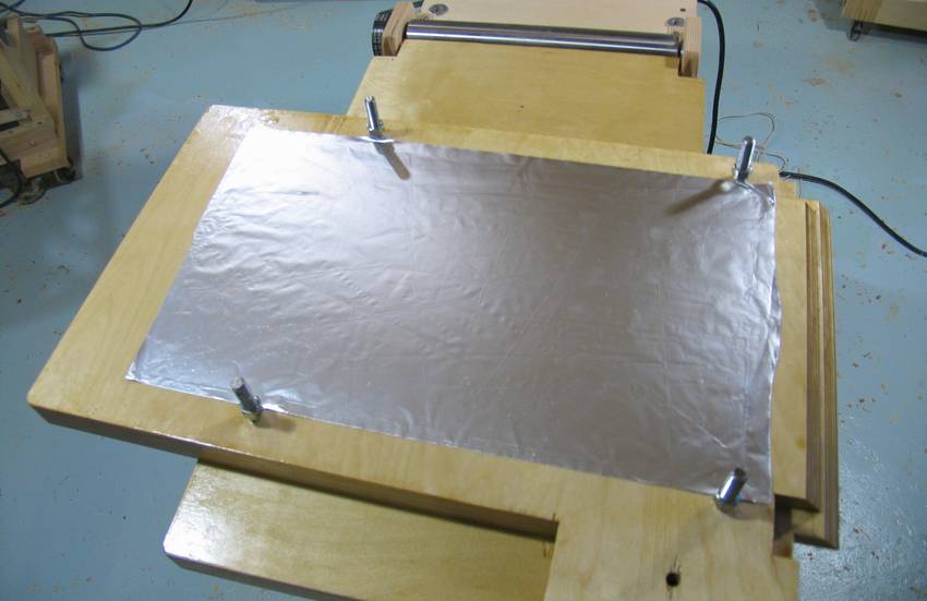 As an extra precaution, I glued some aluminium foil to the bottom of the tables. That way, the wood has
metal on either side. Aluminium doesn't pass vapour, whereas varnish, even oil based, does.
Potato chip bags are always shiny on the inside because they are lined with a thin
layer of aluminium to lock the moisture out. The plastic of the bags alone would
allow water vapour to pass, though very slowly.
As an extra precaution, I glued some aluminium foil to the bottom of the tables. That way, the wood has
metal on either side. Aluminium doesn't pass vapour, whereas varnish, even oil based, does.
Potato chip bags are always shiny on the inside because they are lined with a thin
layer of aluminium to lock the moisture out. The plastic of the bags alone would
allow water vapour to pass, though very slowly.
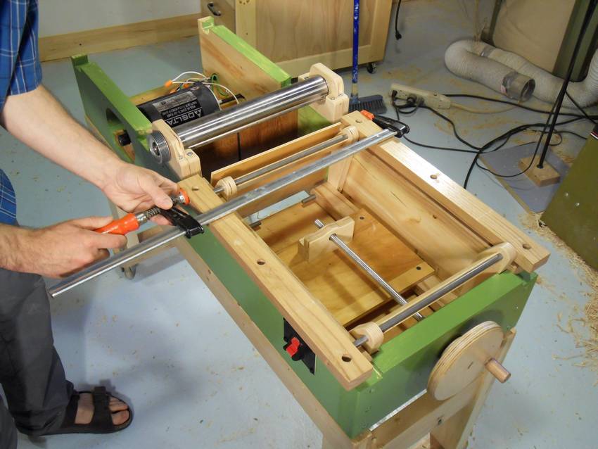 Putting the mechanism back together. A bar clamp turned out to be a much more elegant method of
pressing the rods into their respective holes than hitting them with a mallet.
Putting the mechanism back together. A bar clamp turned out to be a much more elegant method of
pressing the rods into their respective holes than hitting them with a mallet.
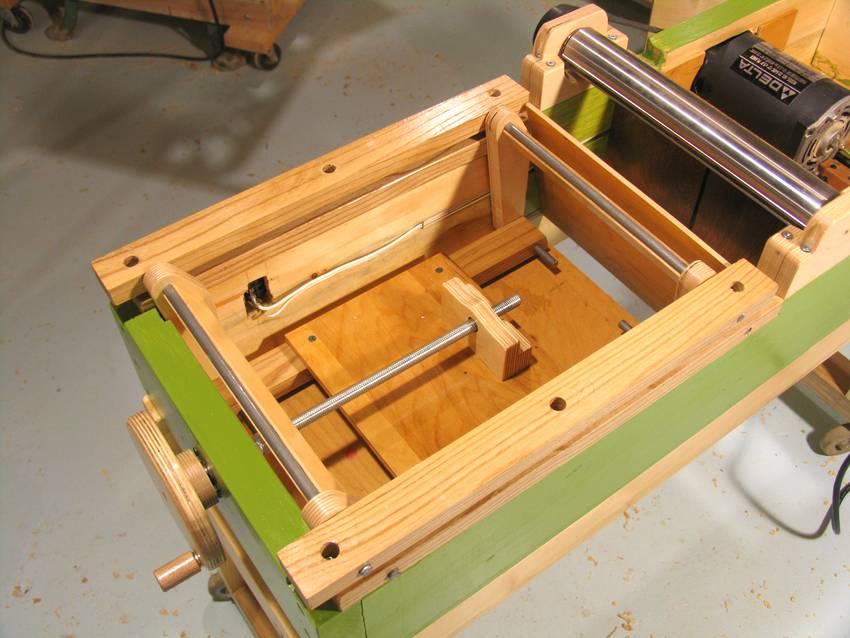
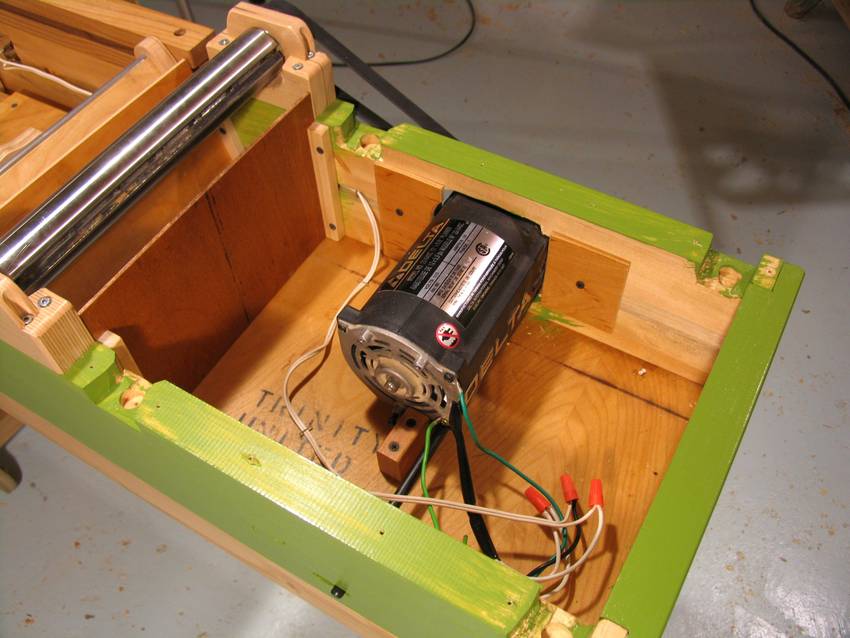 I added some pieces of plywood around the motor opening. The motor pulls air in from the front,
and I want that air to come in through the bottom of the belt housing instead of just
circulating around the motor in the enclosure.
I added some pieces of plywood around the motor opening. The motor pulls air in from the front,
and I want that air to come in through the bottom of the belt housing instead of just
circulating around the motor in the enclosure.
The end of the jointer has some large holes in it to vent the warm air out (not visible in this photo).
I also did the wiring.
 Except for the white cord running to the power switch,
all the wiring in the jointer is in fact the original wiring from the planer.
Except for the white cord running to the power switch,
all the wiring in the jointer is in fact the original wiring from the planer.
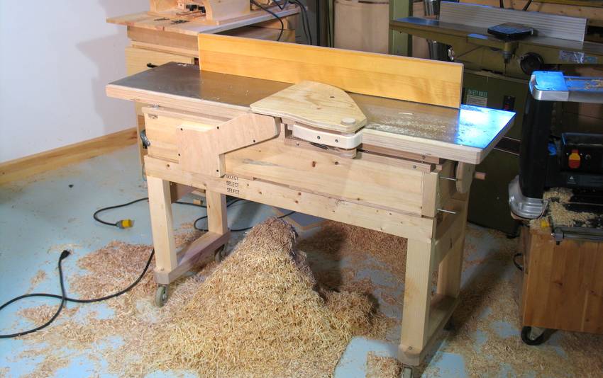
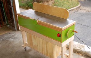
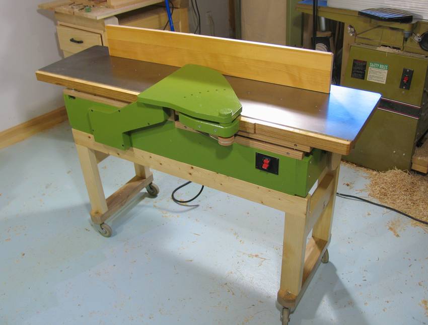 And here's the jointer, all done.
I thought building my own 12" jointer was kind of a nutty project (certainly don't know of anybody who has done it before), but a lot of people have tackled this project themselves since. Here's the first two:
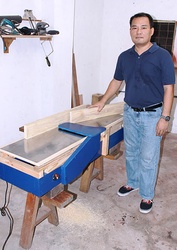
Mike Bourbonnais's jointer
|
Mike Bourbonnais also sent me a lot of pictures and a writeup about his homemade jointer build based on my design. A very nice build! |
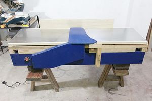 Armand Pedroza has sent me links to his
shop made jointer, loosely based on mine. He posted about the construction of it
in three parts on lumberjocks.com:
Armand Pedroza has sent me links to his
shop made jointer, loosely based on mine. He posted about the construction of it
in three parts on lumberjocks.com:
Part 1 The design
Part 2 Getting started
Part 3 Finishing up
 Plywood on the jointer: bad idea
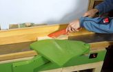 Is wood glue safe on the jointer?
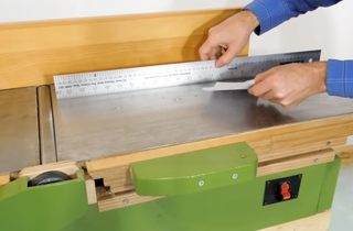 Checking the jointer for accuracy
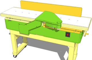 Buy plans for this jointer