 A number of people have sent me a link to
this video of a clever joint on imgur.com.
This joint is also sometimes called a "Kawai Tsugite".
A number of people have sent me a link to
this video of a clever joint on imgur.com.
This joint is also sometimes called a "Kawai Tsugite".
A number of people have sent me a link to
this video of a clever joint on imgur.com.
This joint is also sometimes called a "Kawai Tsugite".
I thought it was novel, but not useful for woodworking. But eventually I figured, if there is so much interest in this type of joint, I might as well play around with it.
The imgur video didn't show the name "Kawai Tsugite", so I initially wasn't able to find out anything else about the joint, so I worked from just the video.
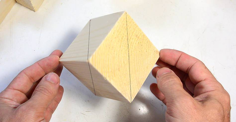
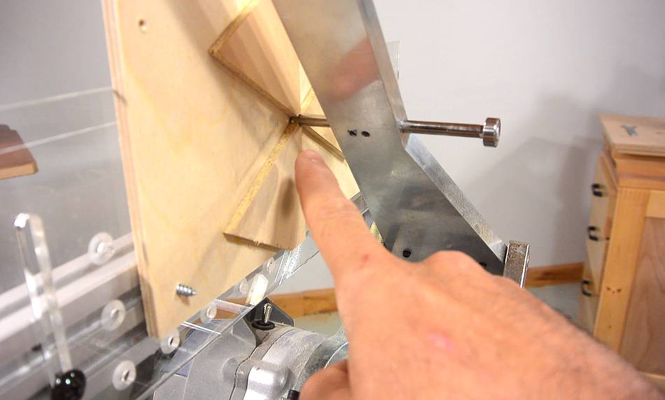
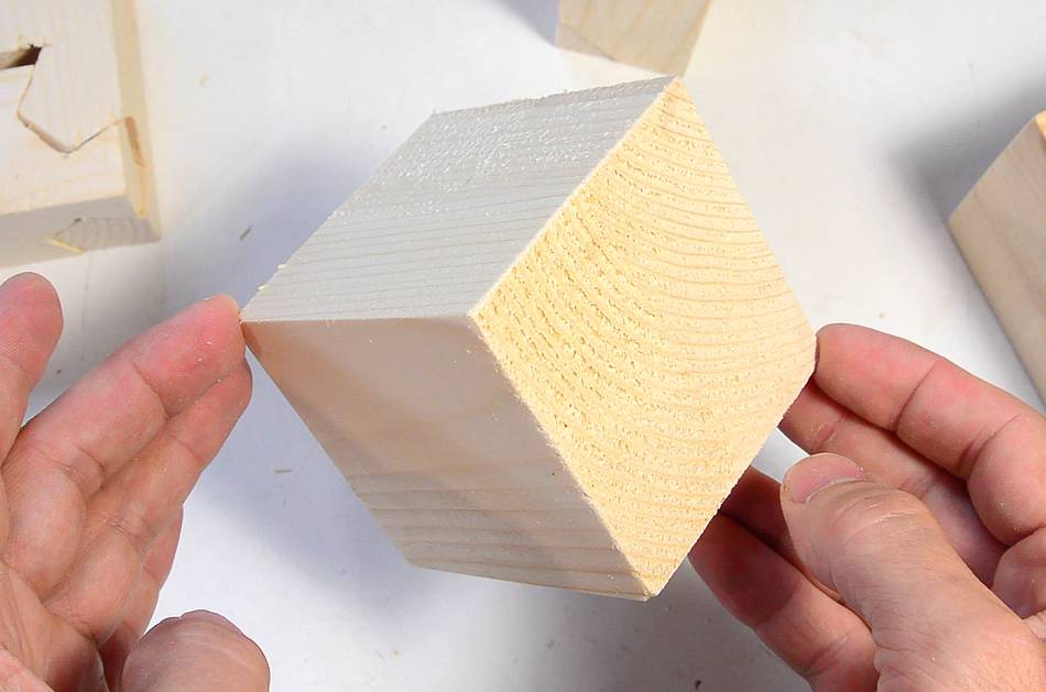 The three-way aspect of this joint is based on the rotational symmetry of a cube
about an axis going through opposite corners. If I spin this cube between
my fingers by 120 degrees (1/3 of a turn), it will occupy exactly the same space
as before.
The three-way aspect of this joint is based on the rotational symmetry of a cube
about an axis going through opposite corners. If I spin this cube between
my fingers by 120 degrees (1/3 of a turn), it will occupy exactly the same space
as before.
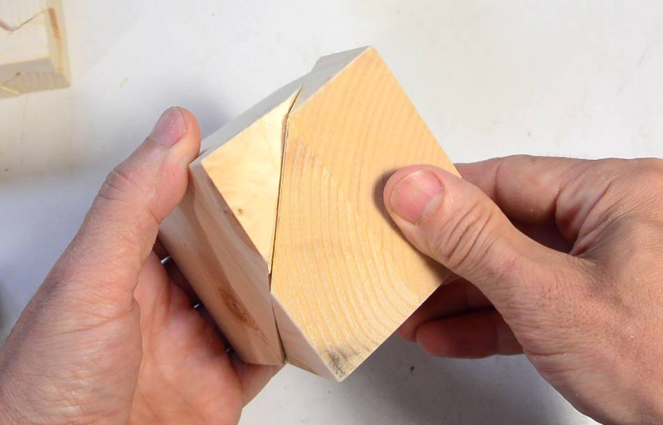 Now, if I cut the cube in half, through a plane perpendicular to that axis, I can rotate
one side of the cube by 120 degrees and the two halves will still form a cube.
This is the basis of this joint.
Now, if I cut the cube in half, through a plane perpendicular to that axis, I can rotate
one side of the cube by 120 degrees and the two halves will still form a cube.
This is the basis of this joint.
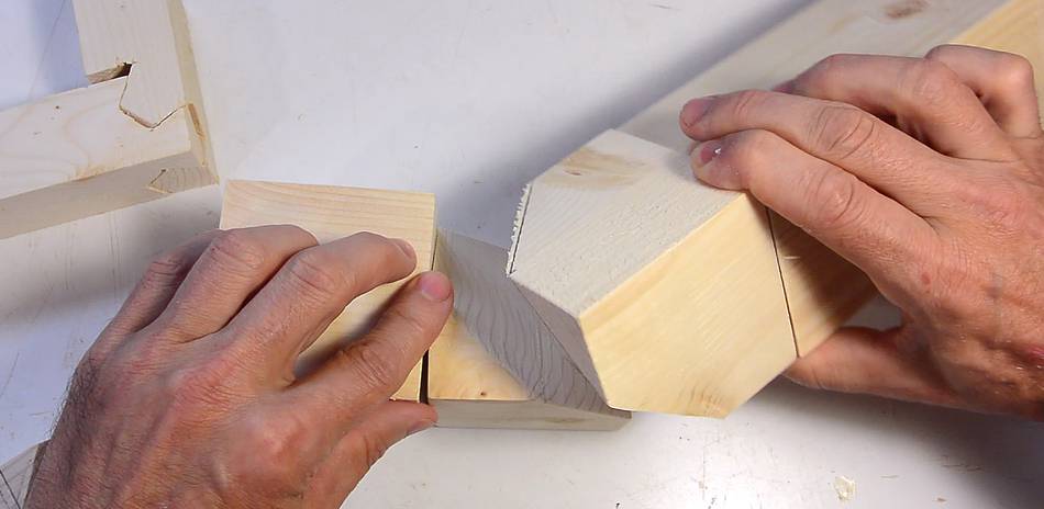
 Now imagine each half of the cube not being just part of a cube, but the end of a
longer square piece of wood. I can now put this together forming a straight joint
or a right angle joint in two ways (with the piece at left fixed, I can make
the piece at right face towards the camera or away from me).
Now imagine each half of the cube not being just part of a cube, but the end of a
longer square piece of wood. I can now put this together forming a straight joint
or a right angle joint in two ways (with the piece at left fixed, I can make
the piece at right face towards the camera or away from me).
 But the cube sliced through in a plane doesn't interlock so it doesn't
make for much of a joint. Ideally, we'd join the cube halves
with some joint geometry that can be assembled at three angles.
The simplest would be something like the joint at left.
So let's make the cube halves join like this.
But the cube sliced through in a plane doesn't interlock so it doesn't
make for much of a joint. Ideally, we'd join the cube halves
with some joint geometry that can be assembled at three angles.
The simplest would be something like the joint at left.
So let's make the cube halves join like this.
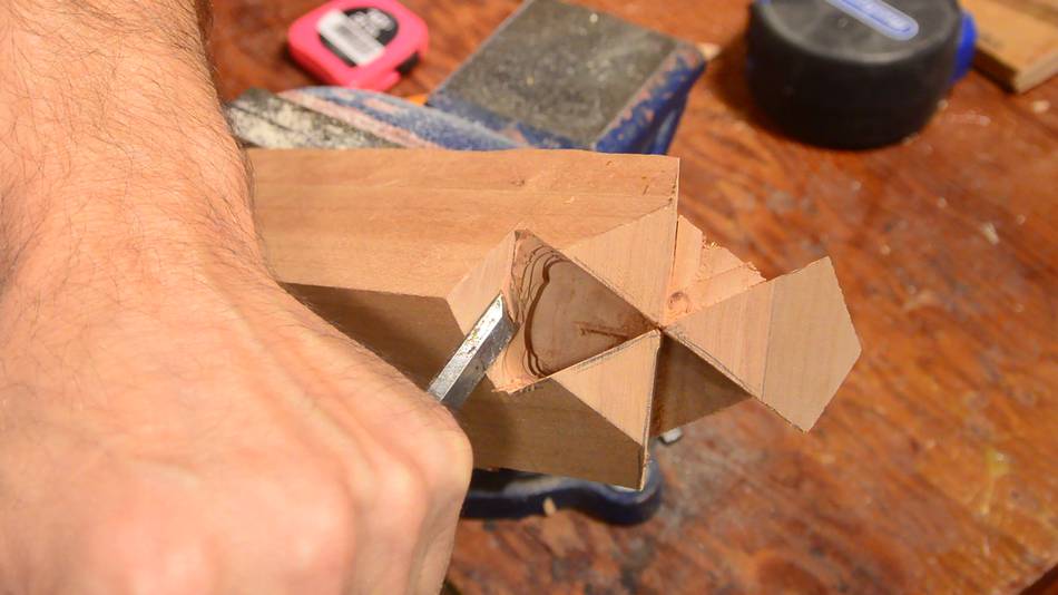
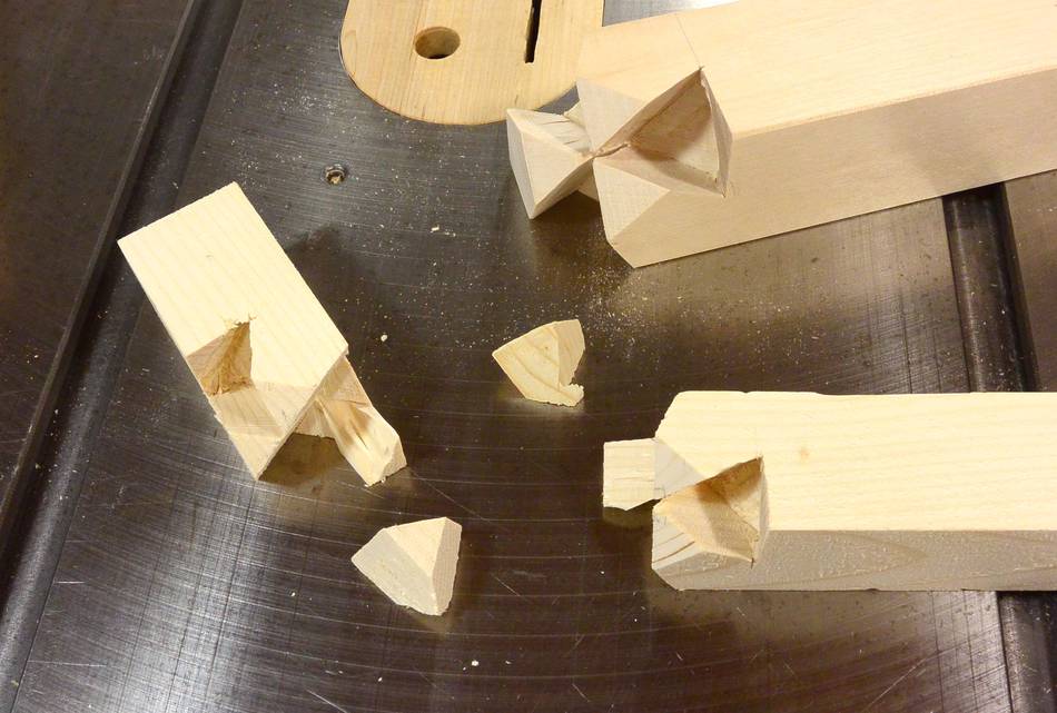
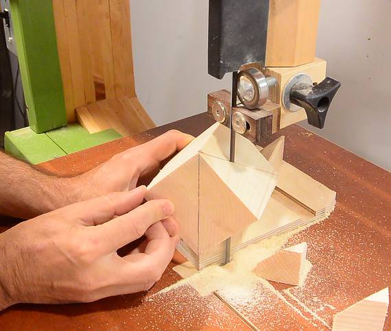 I prototyped the joint by cutting up another wooden cube.
I started by cutting a triangular pyramid off opposite corners.
I prototyped the joint by cutting up another wooden cube.
I started by cutting a triangular pyramid off opposite corners.
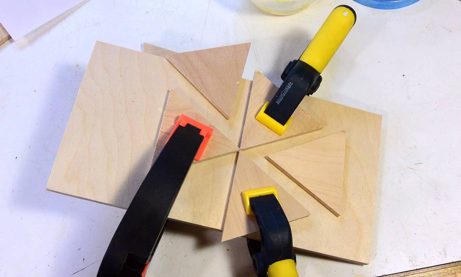
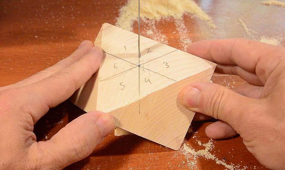 Then cutting the middle part into six equal sized "pie slices"
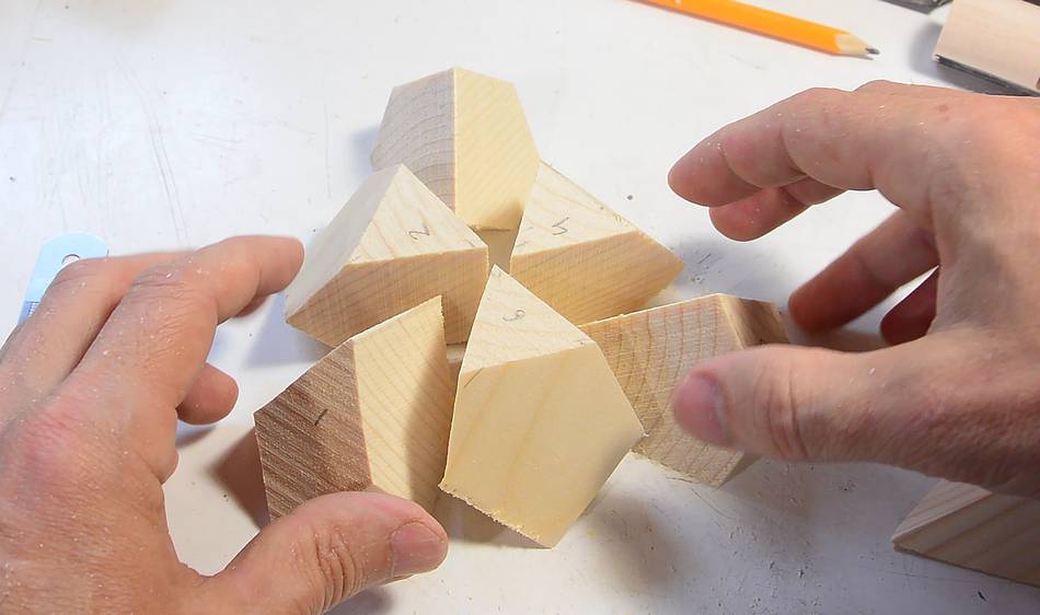 Three of these slices have more area touching the table and the three
that tipped over have a larger area towards the top.
Three of these slices have more area touching the table and the three
that tipped over have a larger area towards the top.
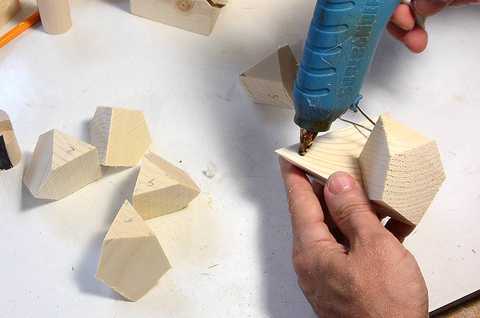 Using hot glue I re-attach three pieces to each triangular pyramid
that I cut off.
Using hot glue I re-attach three pieces to each triangular pyramid
that I cut off.
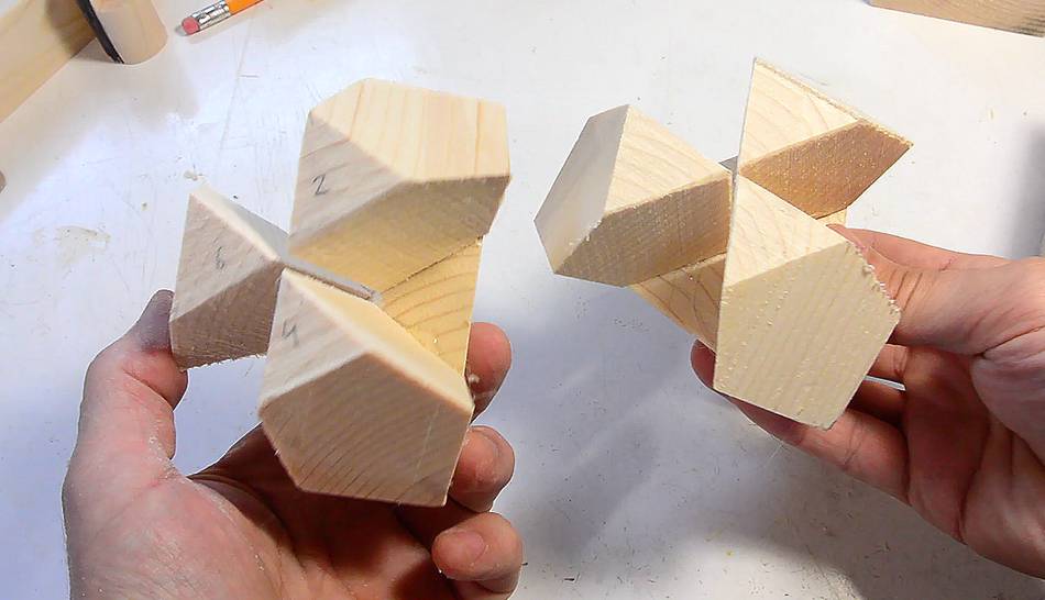
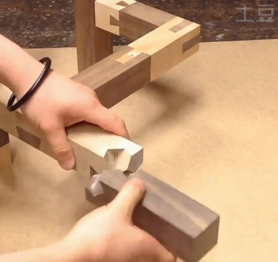
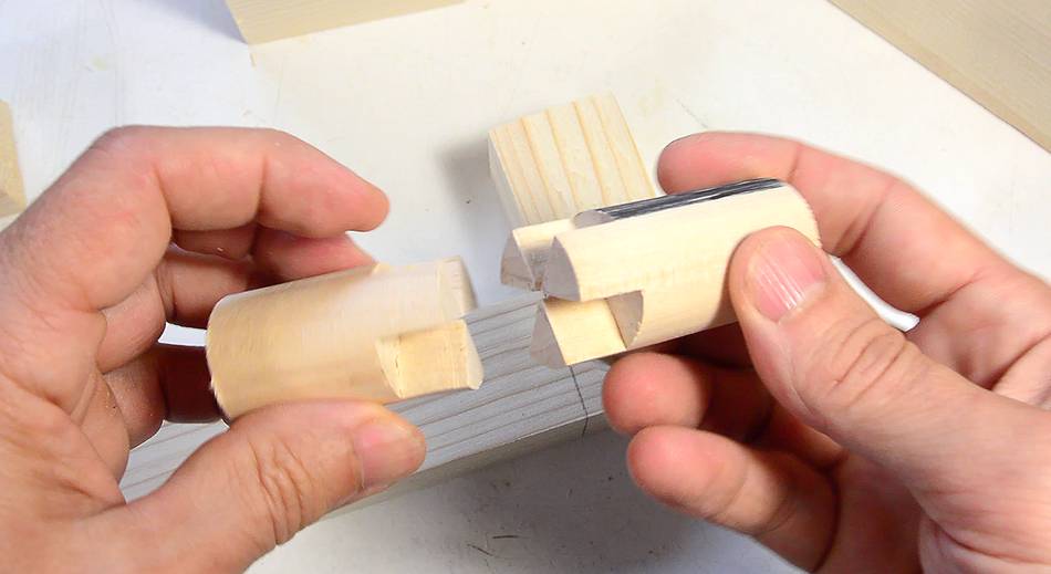
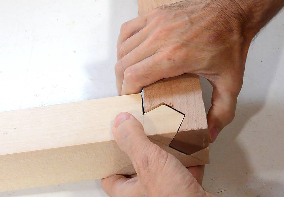
 Here's my two pieces.
They can be slid together in three different orientations.
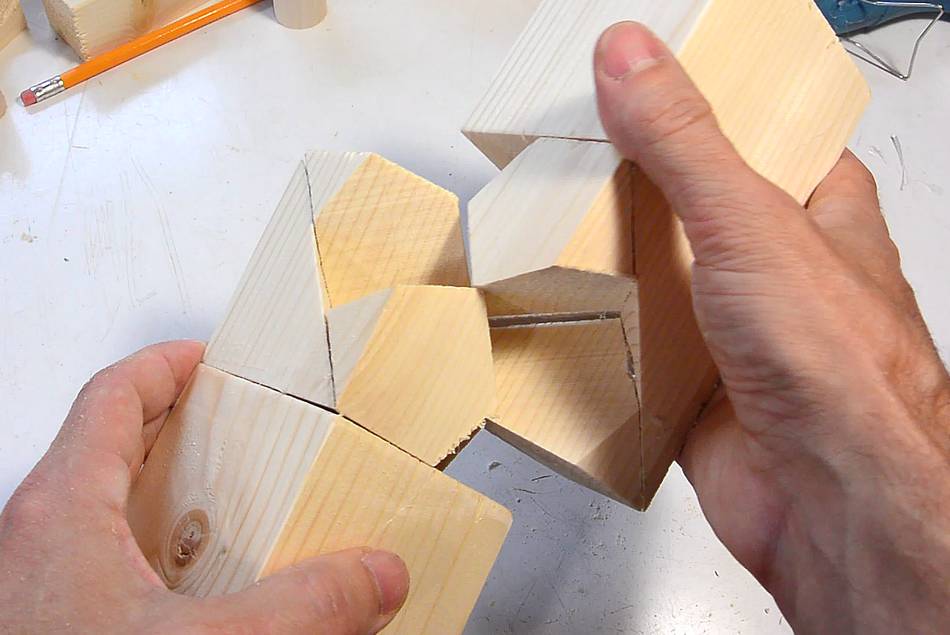
 With a piece glued to the end grain of the joint cubes, I have a joint
that goes together straight or at a right angle in two different ways.
With a piece glued to the end grain of the joint cubes, I have a joint
that goes together straight or at a right angle in two different ways.
So I have the geometry recreated, but crudely with extra cuts and hot glue!
 The next challenge was to carve the joint out of solid wood.
I used some birch and mahogany for colour contrast.
The next challenge was to carve the joint out of solid wood.
I used some birch and mahogany for colour contrast.
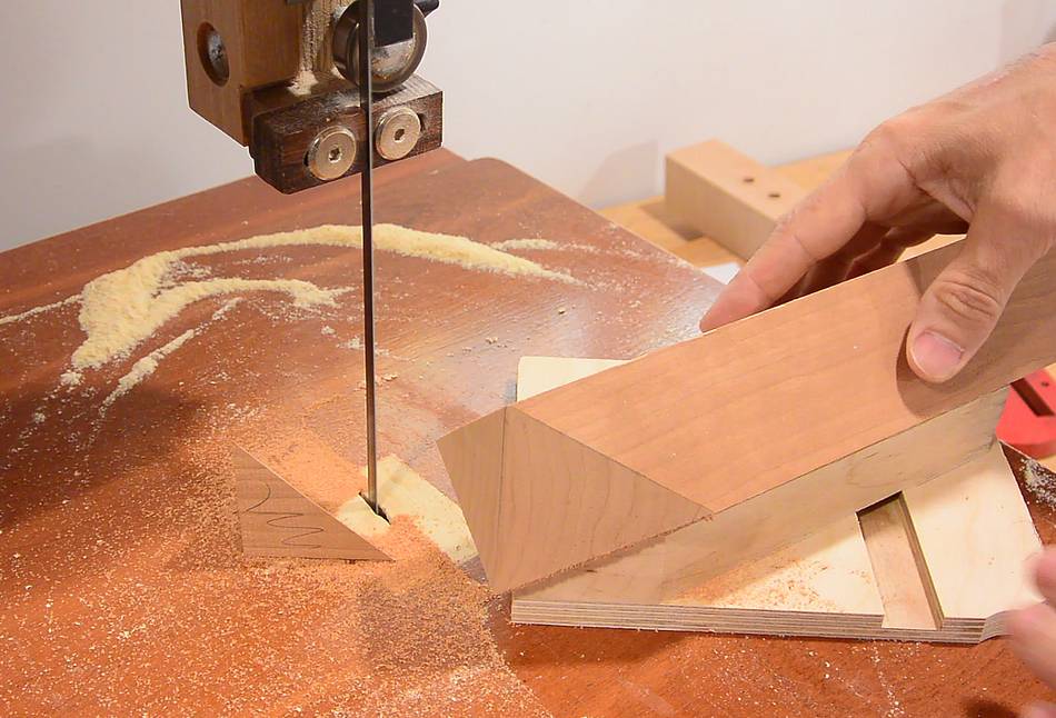
I started by slicing a triangular corner off a piece of square stock, much like I sliced the triangular pyramid corners off my cube.
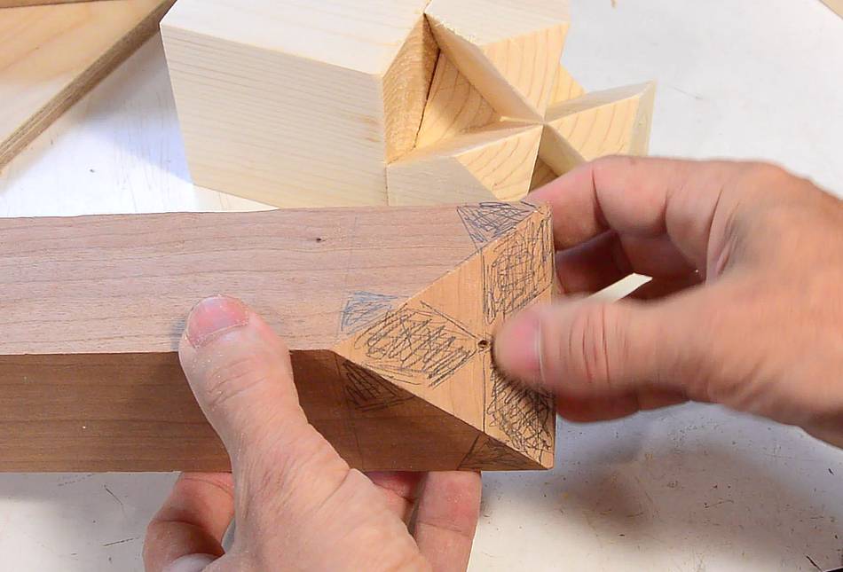 Drawing the joint geometry. I could try to carve this by hand with hammer and
chisels
(like in this Polish video),
but that would take forever. Not my thing. Instead, I'll use one of my
pantorouters
Drawing the joint geometry. I could try to carve this by hand with hammer and
chisels
(like in this Polish video),
but that would take forever. Not my thing. Instead, I'll use one of my
pantorouters
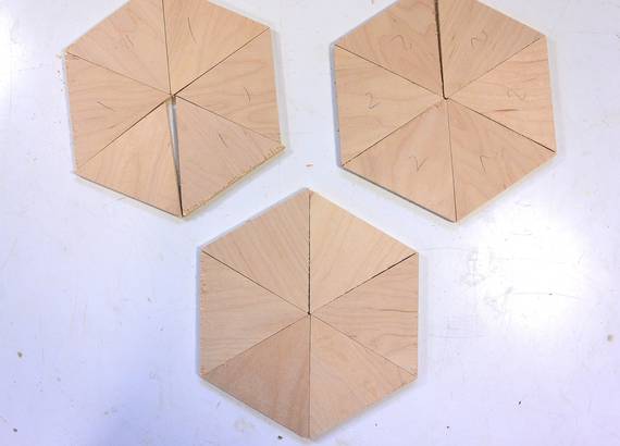 I needed a precise template of the joint. I started by cutting six exactly equilateral
triangles. This was tricky, and I didn't get it accurate enough until the
third try (note the two hexagons with a gap on the right). I glued three triangles
on the template while using the other three to make sure the spacing was correct.
I needed a precise template of the joint. I started by cutting six exactly equilateral
triangles. This was tricky, and I didn't get it accurate enough until the
third try (note the two hexagons with a gap on the right). I glued three triangles
on the template while using the other three to make sure the spacing was correct.
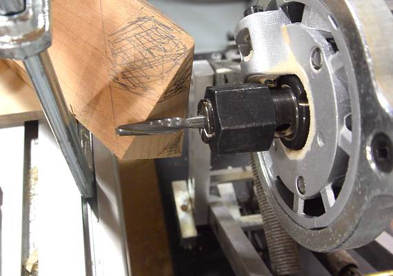
 I then drilled a small hole in the middle of the template so I could stick my
follower pin in there for alignment purposes. I used my
metal pantorouter for this.
The easier vertical adjustment ability came in handy.
I then drilled a small hole in the middle of the template so I could stick my
follower pin in there for alignment purposes. I used my
metal pantorouter for this.
The easier vertical adjustment ability came in handy.

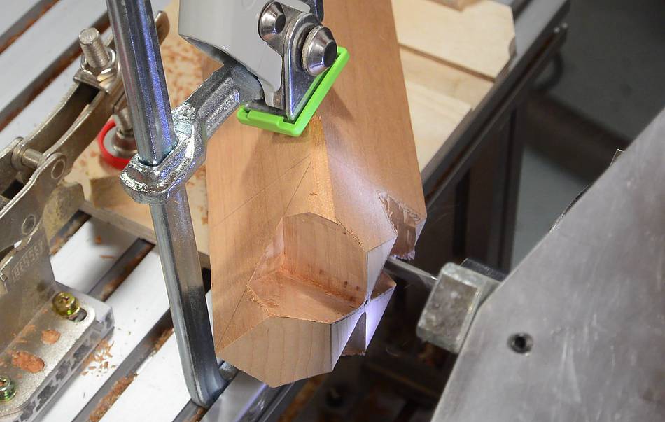
 Lining up the bit with the middle of the pattern. The stock is on a 45-degree
V-block, and at a 35.26 degree angle to the edge of the table.
Lining up the bit with the middle of the pattern. The stock is on a 45-degree
V-block, and at a 35.26 degree angle to the edge of the table.
Depth of cut is set to the rear line that I drew on the stock.
 Then routing it out.
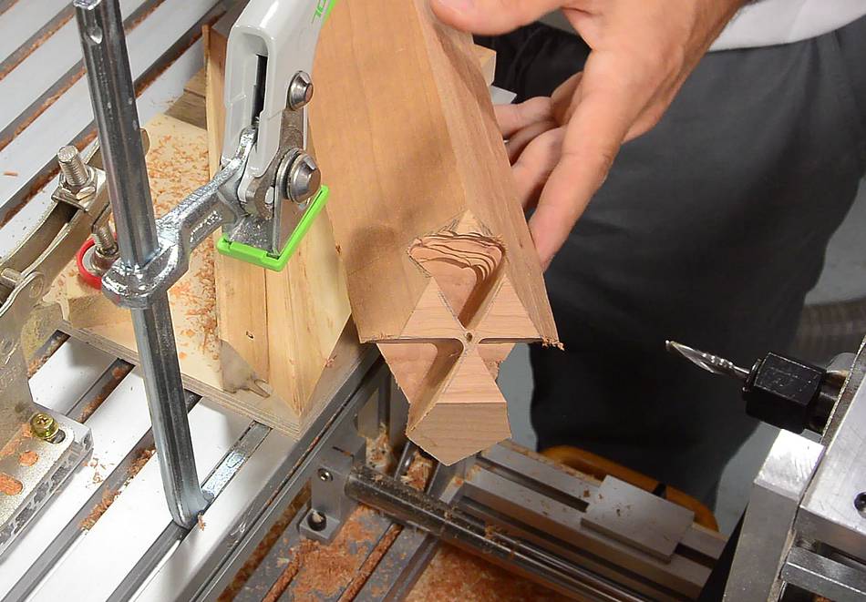 Here is what it looked like straight off the machine.
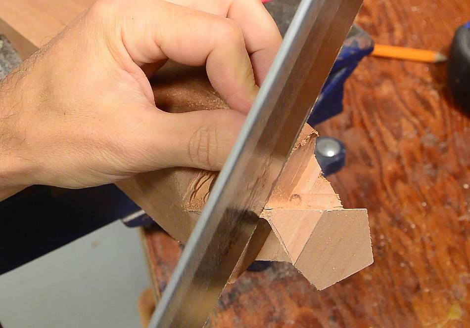
 It needed a bit of cleaning up. Fortunately, much of that could be done just with
a hand saw. Where the corners meet, I could just run a hand saw along the plane that
was cut. This cuts a tiny bit off the converging edges, but I'd do much more damage if I tried
to clean it up with a chisel.
It needed a bit of cleaning up. Fortunately, much of that could be done just with
a hand saw. Where the corners meet, I could just run a hand saw along the plane that
was cut. This cuts a tiny bit off the converging edges, but I'd do much more damage if I tried
to clean it up with a chisel.
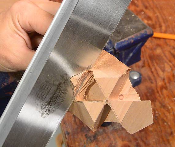
 A bit of chiselling out to flatten this plane, which is perpendicular to
the wood but not to the rest of the joint.
A bit of chiselling out to flatten this plane, which is perpendicular to
the wood but not to the rest of the joint.
 Unfortunately, I didn't leave any "slack" in my design, so it took a bit of chiselling
to loosen up the joint enough that I could slip it together and apart easily.
Unfortunately, I didn't leave any "slack" in my design, so it took a bit of chiselling
to loosen up the joint enough that I could slip it together and apart easily.
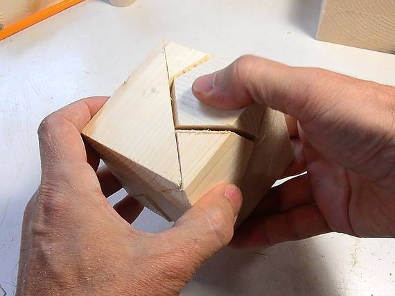
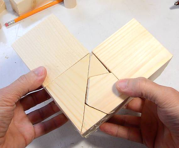
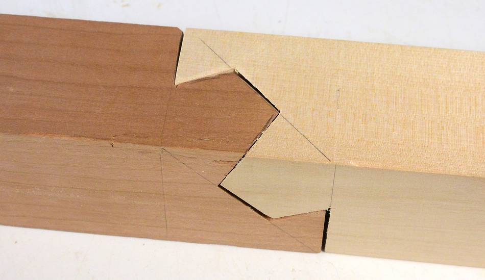 Here in straight configuration...
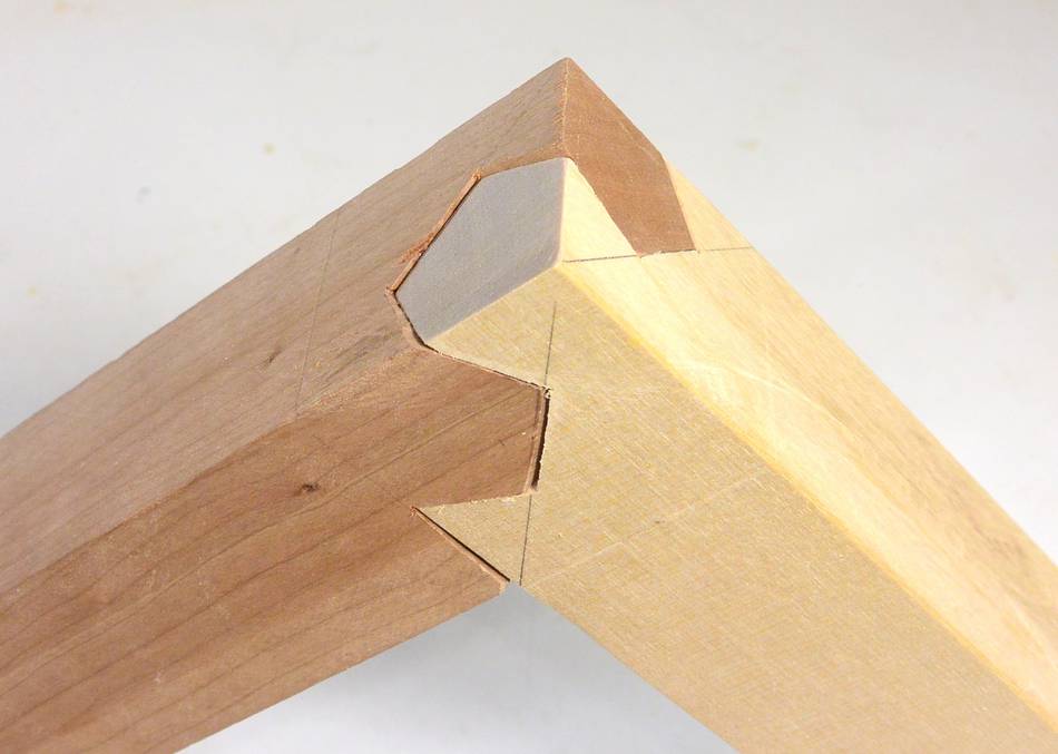 ... and in right angle configuration.
 But this joint is really not a useful woodworking joint. Wood is strongest along
the grain, and this joint doesn't take advantage of that. I stressed an earlier
prototype and it broke very easily. The part at the very end of the joint
breaks off first and once that part is broken, the rest of the joint doesn't
hold together very well.
But this joint is really not a useful woodworking joint. Wood is strongest along
the grain, and this joint doesn't take advantage of that. I stressed an earlier
prototype and it broke very easily. The part at the very end of the joint
breaks off first and once that part is broken, the rest of the joint doesn't
hold together very well.
So the whole thing was more scratching an itch and an exercise in geometry. I certainly won't be using this joint in any practical project. It's way too difficult to get it right and it's not a strong joint.
I also made a Sketchup model of the joint.
You will need SketchUp CAD program
to open this file.
It was only after building the joint that I searched for more stuff
and realized people call it a "Kawai Tsugite". Once I knew that, I was
able to find more about it online. For example:
Matt Cremona on the Kawai Tsugite ,
or this 3d printed one.
3d printing may not be ideal for this. The best way to make this joint is to mount
the wood at a 35.26 degree angle on a CNC machine or pantorouter.
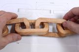 Wooden chain
carved using only power tools
Wooden chain
carved using only power tools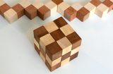 Snake cube puzzle
 Impossible looking
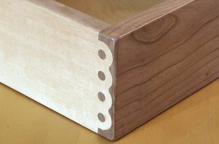 Knapp jointed box
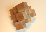 Wooden assembly
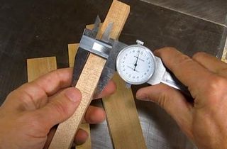 Making precise cuts
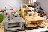 More about the
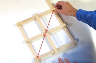 How the pantorouter
 Table saw fence