
Foreword (by Matthias)
Pekka Svinhufvud, from Finland, emailed me asking about whether my bandsaw plans could be scaled down to 250 mm wheels. He also sent me some pictures of some of his homemade machines. I'm always curious about other people's homemade machines, so I offered to send him the bandsaw plans for free if he could send me more stuff to publish about his machines. Pekka sent me these pictures, plus a long write up. The write up was probably translated to English with Google Translator, and it needed some work to coax the meaning from what at times looked like a jumble of words. I have done quite a bit of editing to the text, so while the content of this article is by Pekka, half the wording is mine.
Although editing was a lot of work, it was very enjoyable to see somebody else's engineering approach, solving the same problems I had to solve, sometimes similar, sometimes completely different. The bandsaw to some extent reminds me of my first homemade bandsaw. I believe I have since then managed to simplify the design and construction of homemade bandsaws with my bandsaw2 and bandsaw/sawmill
Pekka writes:
The first bandsaw I owned was a three-wheeled, metal-bodied hobbyist quality machine. It proved to be too small and made poor quality cuts.
I decided to make my own 300mm (12") saw out of plywood. The only ready-to-buy parts I used were the blade and bearings. I installed the motor from my lathe, which was left over when I changed it to a three-phase motor. This has worked perfectly for years. The biggest deficiencies are lifetime of the blades in and that it can not have a very thick and stiff blade because the wheels are so small. The saw motor is only 250 watt, cutting height is 160 mm and a width of 315 mm. Also the wheel bearings also don't have enough support.
The frame is made from 35 mm birch plywood. The plywood I used is inexpensive compared to prime. Still, it is almost flawless with the exception of a few dirt tracks from manufacturing. I paid about 16 Euro per square meter for the 35 mm thick plywood. The wheel hubs, table top, bearing supports and front cover are made from 20 mm birch plywood. I used about 1.5 square meters of the 35 mm plywood and 3 square meters of the 20 mm plywood.

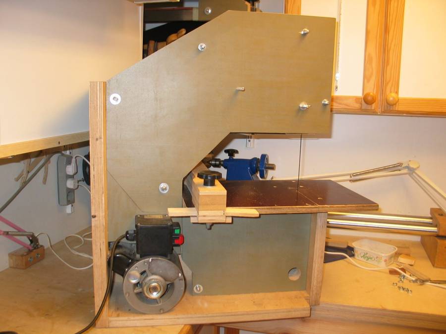
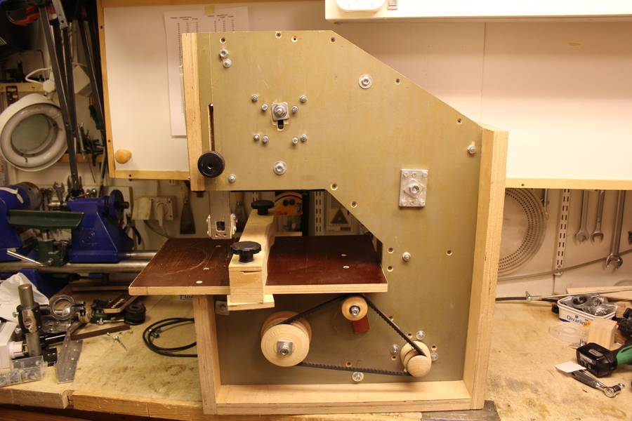
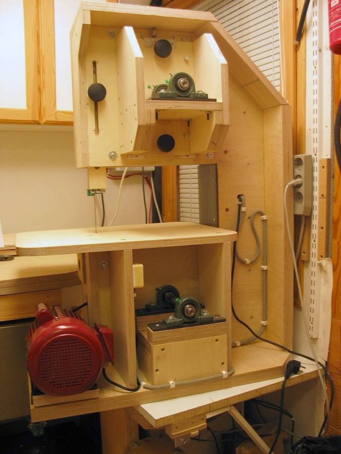
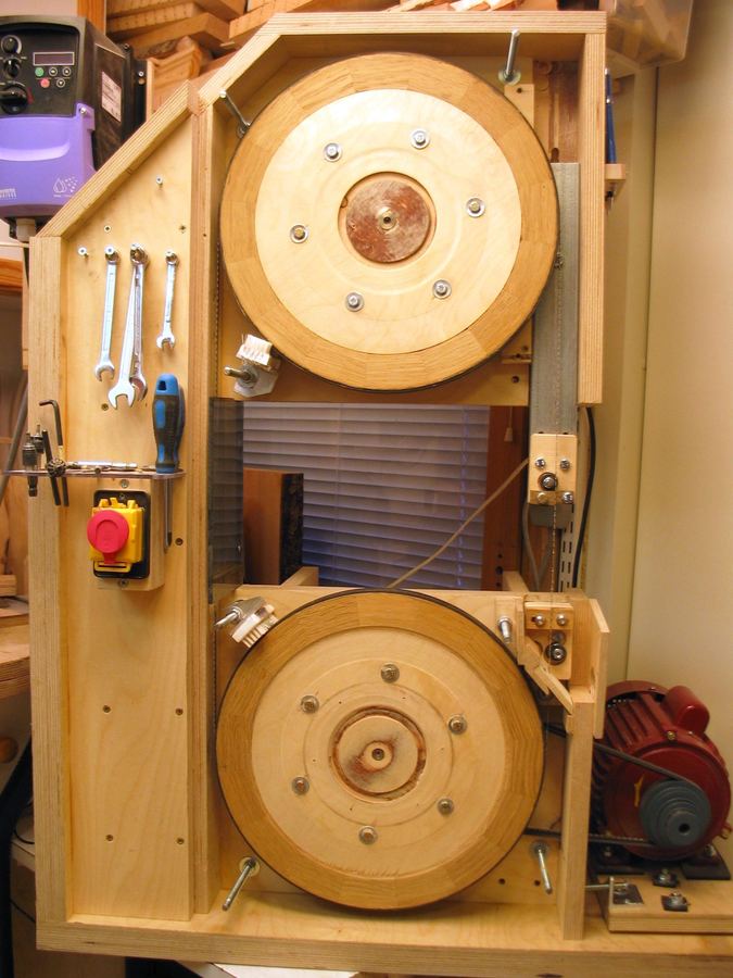
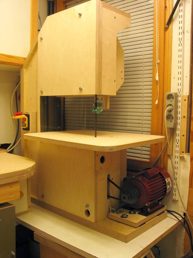
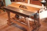
The above images show the main structure of the saw.
Design goals were: sturdy, heavy, quiet, and will sit on an existing table. To be constructed at home, with the exception of the shafts. Also effective sawdust removal and adjustable cutting speed.
A friend of mine made flanged shafts on his metal lathe. I provided him two pieces of 18 mm steel plate and 20 mm diameter pieces of steel shaft, 290 mm long. 200 mm wafers were turned and welded to the shafts as directly as possible. Flanges were turned straight and on the shaft. This was the demanding phase of construction. Thanks again for your help, Rauno. The shafts are mounted in self-aligning pillow block bearings, type P204. The bearings have self-locking screws so they are easy to attach to the shaft in the correct position. Cast iron bearings and pillow blocks are cheap (8 Euro each) and work well for this application.
To calculate the pulley ratio, one must first select the speed of the blade. Smaller saws use 300 to 900 m/min speeds. With a wheel diameter of 350 mm one revolution takes the blade: 0.35 * 3.14 = 1.1 m. Now we can calculate the needed RPM for 300 and 900 m/min: 300 / 1.1 = 273 RPM and 900 / 1.1 = 819 RPM. The motor rotates 1425 RPM. The motor's smallest pulley is 38 mm and the largest is 79 mm. For the low speed and smallest motor pulley, we work out the other pulley diameter: 1425/273 * 38 = 197 mm and for the highest speed and largest motor pulley, we work out: 1425/819 * 79 = 137 mm I decided to make only one pulley so I compromised with a diameter of 180 mm. I turned the pulley from 20 mm plastic plate and attached it to the flange of the rear surface of the wheel. Working it out from there, the available blade speeds with the pulley steps are 330, 435, 566 and 687 m/min.
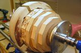
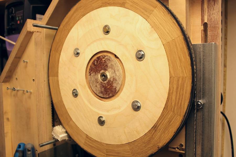 Next, I made a wheel outer circumference from 22 mm oak. The wheel
diameter is 350 mm. I cut a number of equal length
segments with very accurate angles, and they are glued together in
pairs first, then pairs to each other until it's half a circle.
I matched them by grinding the ends straight in order to ensure a
good adhesive bond. Then the half circles are glued together. The segment's
long side length is calculated using the formula (outer diameter * 3.14
/ number of segments). Accurate joints require accurate cutting.
I have a homemade table saw and a sliding adjustable miter
gauge. Segment rings can be done, for example 8, 12.16, etc. segments
per ring. After the glue dried, I turned the inside of the ring, then
glued it onto a round 200 mm plywood disk.
Next, I made a wheel outer circumference from 22 mm oak. The wheel
diameter is 350 mm. I cut a number of equal length
segments with very accurate angles, and they are glued together in
pairs first, then pairs to each other until it's half a circle.
I matched them by grinding the ends straight in order to ensure a
good adhesive bond. Then the half circles are glued together. The segment's
long side length is calculated using the formula (outer diameter * 3.14
/ number of segments). Accurate joints require accurate cutting.
I have a homemade table saw and a sliding adjustable miter
gauge. Segment rings can be done, for example 8, 12.16, etc. segments
per ring. After the glue dried, I turned the inside of the ring, then
glued it onto a round 200 mm plywood disk.
Disks are bolted to the flange shafts with 6 mm bolts. Since the wheel has to be as balanced as possible, I turned them rotating on their bearings straight and circular.
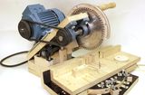
 I built a wooden platform to attach the bearings on my
lathe. Because my lathe's spindle height was not enough for
such a large work piece, I put spacers under the lathe's
drive head to bring it up further.
I built a wooden platform to attach the bearings on my
lathe. Because my lathe's spindle height was not enough for
such a large work piece, I put spacers under the lathe's
drive head to bring it up further.
The lathe's drive shaft is coupled to the shaft with a piece of hose. Wood moves with changes in moisture as it dries, so I left my wheels until completion of the frame. Before gluing the outer rubber ring (tire), I turned the outer rim one more time. The advantage of the above-described technique with the segmented outer ring is that the grain direction is parallel to the ring, so the moviements due to moisture content changess are smooth and radial.
3 mm sheet rubber strips were glued on with contact cement. The seams are beveled so that the blade runs smoothly on the wheel. I turned and sanded the rubber as a round cross-section and slightly convex. Convexity makes the blade track on the middle of the wheel.
 The rear, side, and bottom plates are load bearing structures and
are made of 35 mm plywood. The panels are cut and drilled
before screwing and gluing together.
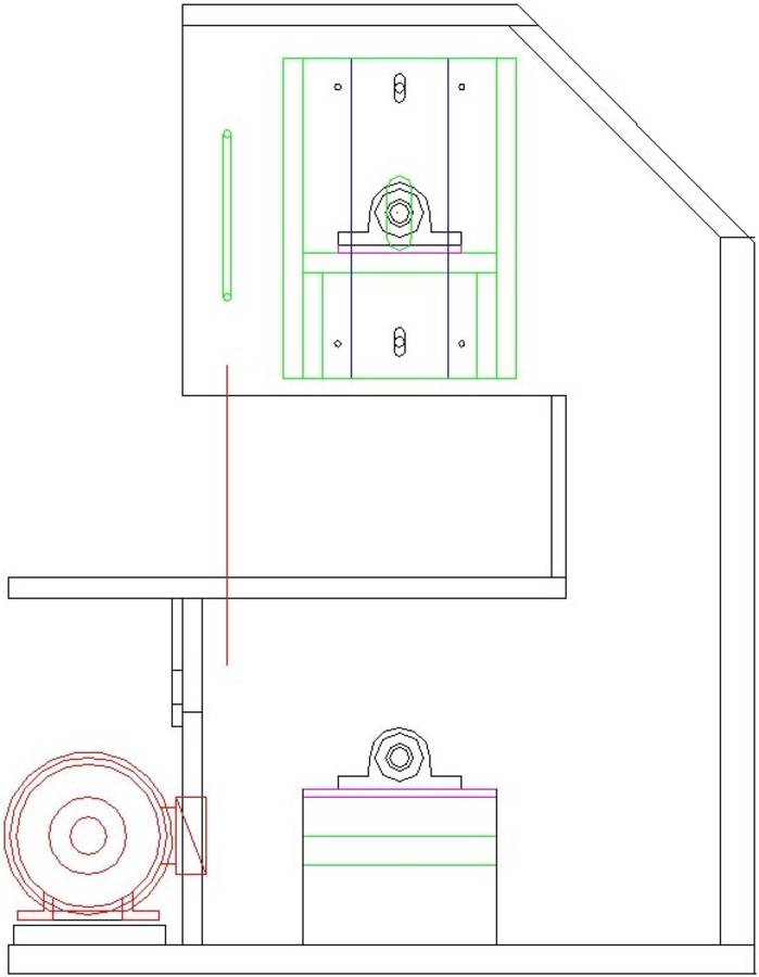
The drawings earlier on this page show the cross bracing on the left of the frame
The cross bracing increases the frame stiffness against twisting.
The rear, side, and bottom plates are load bearing structures and
are made of 35 mm plywood. The panels are cut and drilled
before screwing and gluing together.
The drawings earlier on this page show the cross bracing on the left of the frame
The cross bracing increases the frame stiffness against twisting.
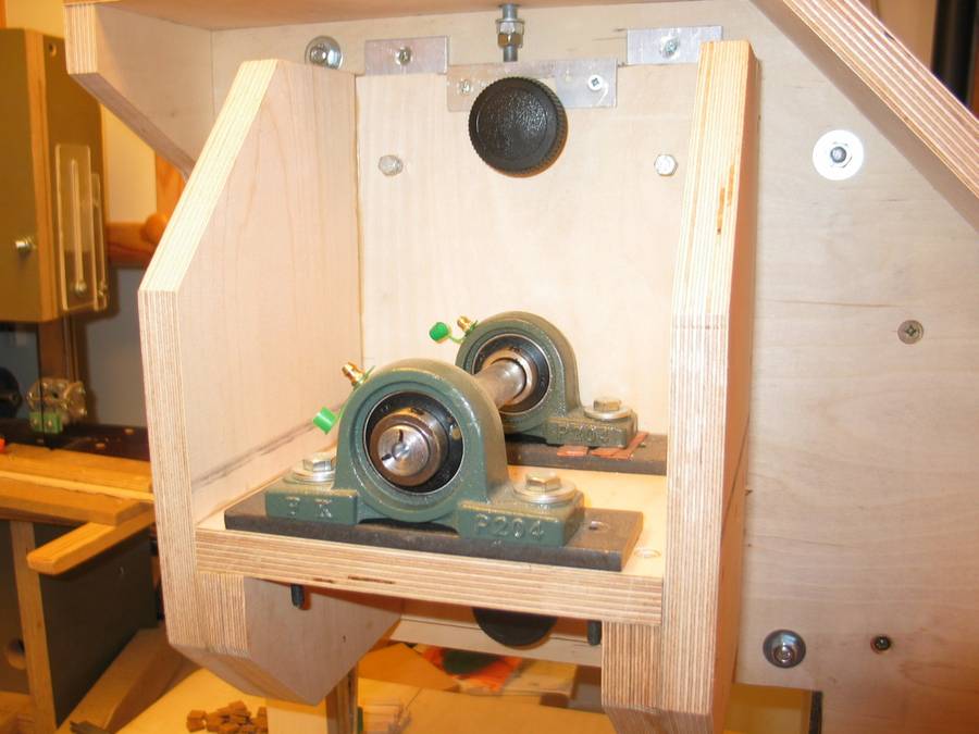
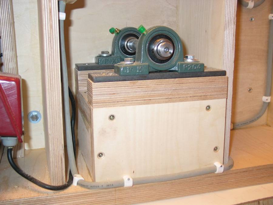
Bearing brackets are made of 20 mm plywood. The bottom one is a simple
rectangular box. The shaft is adjustable so that the wheel is
parallel to the frame plate. Wheel vertical alignment adjustment is made,
if necessary, by putting washers under the bearings.
The upper bearing bracket can be moved vertically and tilted if necessary. The blade is tensioned by turning the screw on the top.
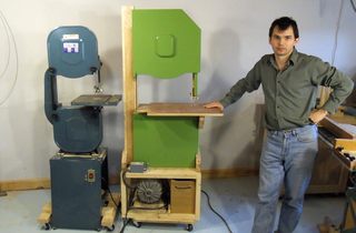
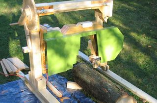
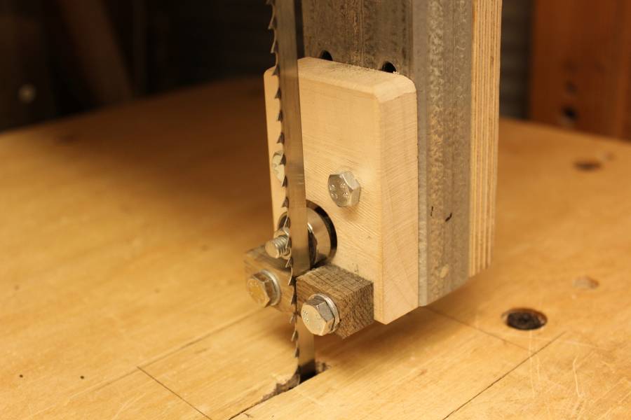 I tried to make the blade guides stiff, silent, cheap, and easily
adjustable. I tried guide bearings in my previous saw, but they did not
last and were noisy. So I replaced them with wear resistant green plastic blocks.
The plastic is so wear resistant that it was impossible to shape with sandpaper.
I tried to make the blade guides stiff, silent, cheap, and easily
adjustable. I tried guide bearings in my previous saw, but they did not
last and were noisy. So I replaced them with wear resistant green plastic blocks.
The plastic is so wear resistant that it was impossible to shape with sandpaper.
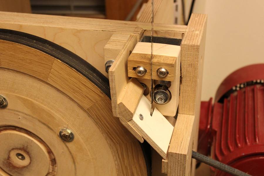 For this saw I made guide blocks from pieces of hardwood.
The upper support is height adjustable for different cutting thicknesses.
The bottom is fixed, but both guides can be adjusted laterally.
For this saw I made guide blocks from pieces of hardwood.
The upper support is height adjustable for different cutting thicknesses.
The bottom is fixed, but both guides can be adjusted laterally.
The blade guides are mounted to 50 * 25 * 3 mm steel channel. For the upper guide, I routed a 50 mm wide groove in the back plate. The support moves in this groove. A slot is milled into the back plate, and a screw locks the guide column to the back with a hand wheel.
The table top is made from 20 mm plywood and is attached to the frame with wood screws. Table is not tiltable because it would introduce structural challenges and limit cutting height. I don't need to tilt the bandsaw because it's easier and more accurate to cut bevels on the table saw. Small angles can be cut if you can install a wedge under the table.
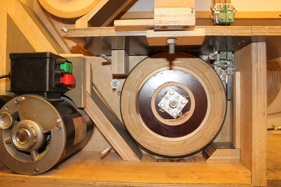
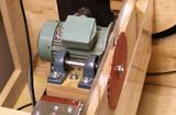
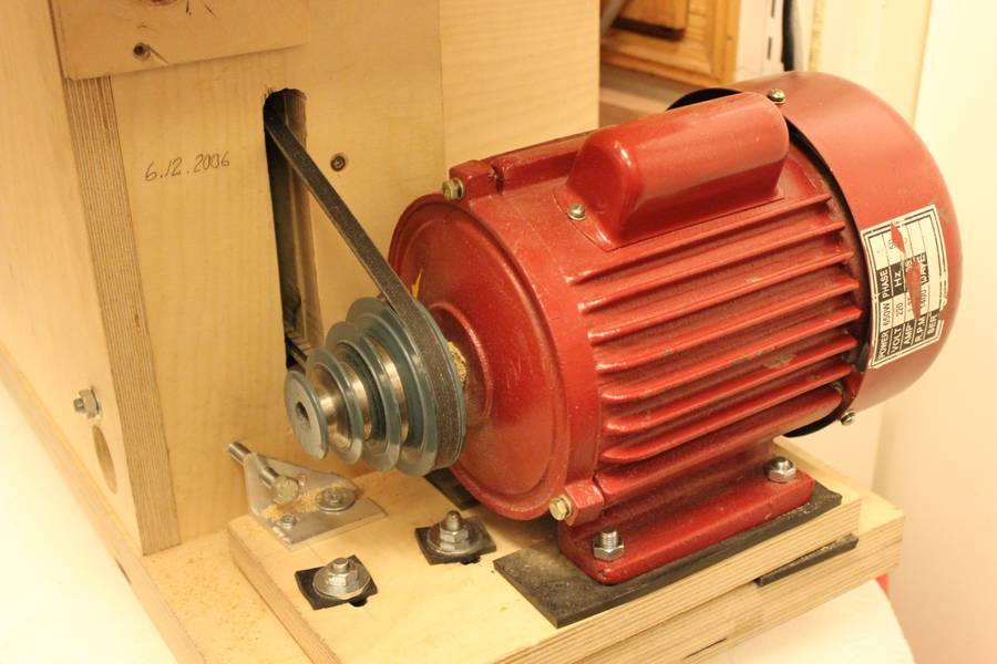 The motor is attached with pieces of
rubber on top of the plywood, and this is locked to the frame below
with two bolts. Speed changes can be made with four threaded holes
in the plate to align the motor for the selected belt groove.
The belt tightening screw can be seen in the photo.
The motor is attached with pieces of
rubber on top of the plywood, and this is locked to the frame below
with two bolts. Speed changes can be made with four threaded holes
in the plate to align the motor for the selected belt groove.
The belt tightening screw can be seen in the photo.
 When constructing such a machine, the adjustment and tuning is
interesting. First, adjust the wheel axles so that the
wheels are at the same distance from the back plate, then lock the
setscrews on bearings. Adjust the wheels as parallel as possible with
each other by measuring the distance between the wheel and back
plate with calipers. Measure on the left side, then turn the
wheel half a turn, and measure from the same spot on the wheel
on the right side. If the measurements differ, the bearing
blocks need to be moved sideways.
When constructing such a machine, the adjustment and tuning is
interesting. First, adjust the wheel axles so that the
wheels are at the same distance from the back plate, then lock the
setscrews on bearings. Adjust the wheels as parallel as possible with
each other by measuring the distance between the wheel and back
plate with calipers. Measure on the left side, then turn the
wheel half a turn, and measure from the same spot on the wheel
on the right side. If the measurements differ, the bearing
blocks need to be moved sideways.
Next measure the wheel alignment in the vertical plane. This is best done with a bandsaw blade installed and tensioned. The method is similar to the previous procedure, but installing shims under the bearings to make adjustments.
Check whether the upper blade guide is parallel to the blade. Raise the blade guide up and adjust one of the guide blocks to touch the blade. Lower the blade guide and the guide block should still touch the blade but not deflect it. Adjustments can be made by moving either wheel side to side.
With the blade in place and tightened, rotate the wheels by hand a few times back and forth to see if the blade tracks nicely on top of the wheel. If the blade does not line up with the middle, the upper wheel must be tilted in the vertical plane with the bracket screws.
The blade guides are adjusted so that the back of the bearing almost touches the back edge of the blade. The guide blocks are adjusted to touch the blade.
The blade should be perpendicular to the table. Cut a piece off the end of a straight board, with the board oriented upright. Then flip the board top and bottom and cut another piece off. Measure the length of the cutoff on both sides. I learned this trick from a famous segmented wood turner Curt Theobald. He used the method on his video to adjust his disk sander.
 As I write this, I have used the saw 5 years and the experience is
positive: the cuts are excellent. It is easy to cut thin veneers, veneer
thickness will vary by 0.1 mm. The saw runs quiet and works well
for sawdust removal. Motor power is adequate.
As I write this, I have used the saw 5 years and the experience is
positive: the cuts are excellent. It is easy to cut thin veneers, veneer
thickness will vary by 0.1 mm. The saw runs quiet and works well
for sawdust removal. Motor power is adequate.
Have fun!
Pekka
See also:
 Pekka's homemade
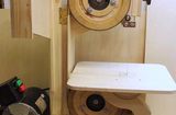 Pekka's small bandsaw
 Jim Wheeler's bandsaw
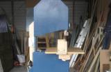 More reader built
Back to woodgears.ca
![]()
 Homemade bandsaw / sawmill build