Having experimented with different impeller shapes, my
next experiments focused on the shape of the housing.
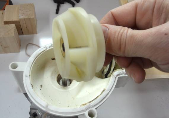
I was using a dishwasher motor, about 0.1 hp, and I just happened to see another
dishwasher like that on the curb and took the motor out of that. The impeller
has backward curved vanes, which gives me added confidence
that that shape is best. And the housing was also roughly spiral shaped.
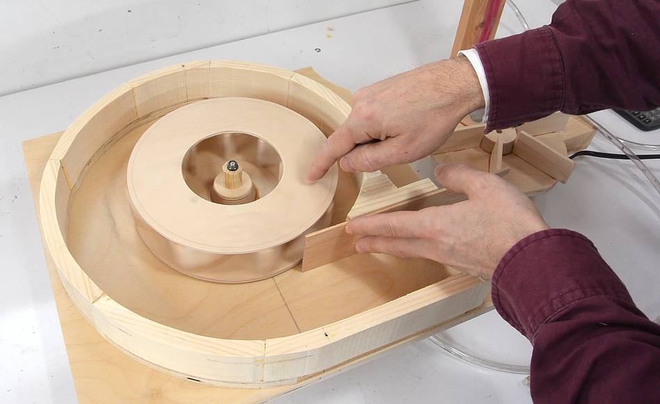
The closer the housing gets to the impeller's blades, the louder it gets, so
I always leave a bit of space between. I wanted to experiment to see if the size
of that space made a difference. I figured it might help to "cut"
the air stream closer to the impeller by sliding a piece of wood in from
the blower's exhaust port.
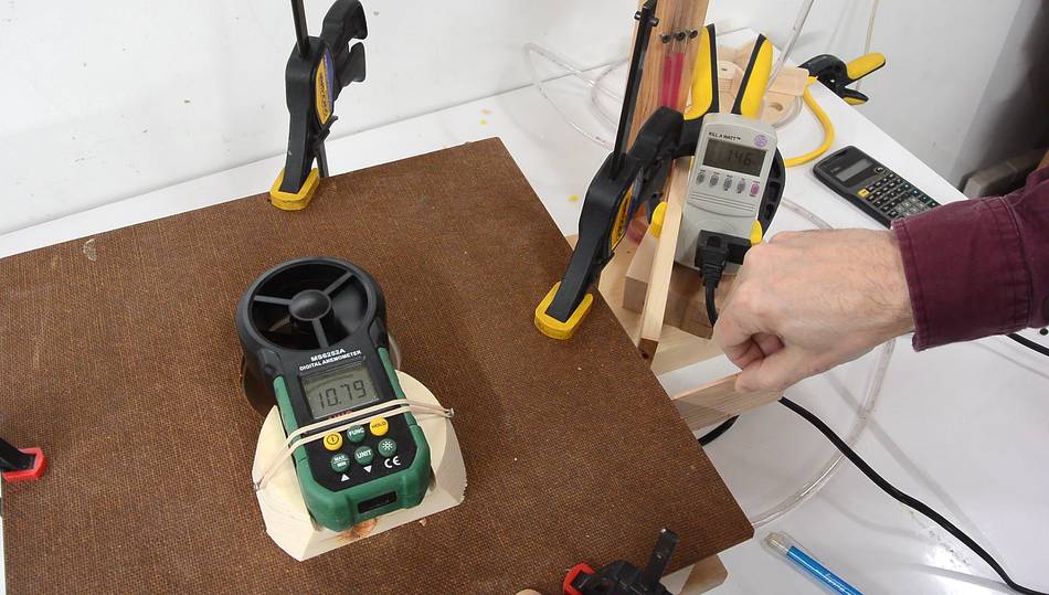
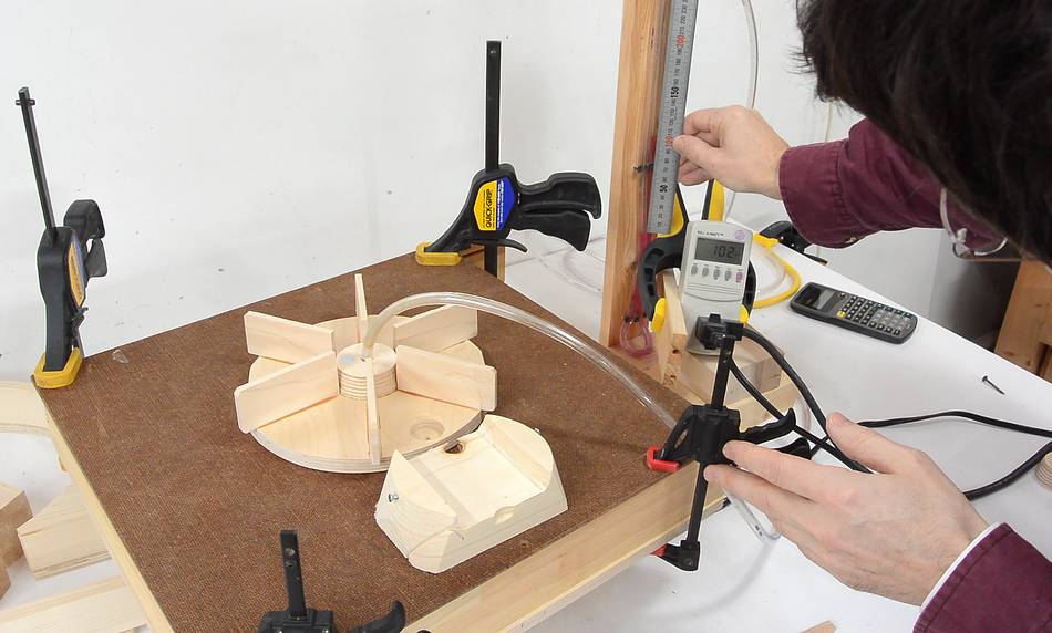
I made a wooden bracket to hold my anemometer a consistent distance above
the blower's intake. With the blower running, I slid the piece of wood in
the exhaust port. As expected, the blower became much louder. But the airflow
did not increase, nor did the motor's power consumption drop any.
I repeated the experiment, but blocking the blower's inlet (using the straight
impeller from earlier experiments). When inserting the strip of wood,
if anything, suction pressure dropped slightly.
So it appears there are no benefits to cutting the air stream closer to the
impeller.
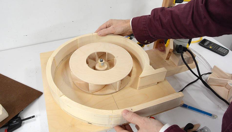
My next experiment was to shift the housing to the right, so that the impeller
has about the same amount of room around it most of the way (and the air stream
isn't cut as close).
This increased static pressure from 11.5 cm to about 11.7 cm, but unrestricted
air flow measured at the inlet dropped from 11 m/s to 10.5 m/s.
My guess is that having a good circular space around the impeller allows the air
beyond the impeller to go in circles around the impeller. The centrifugal force
acting on that circulating air contributes to suction pressure.
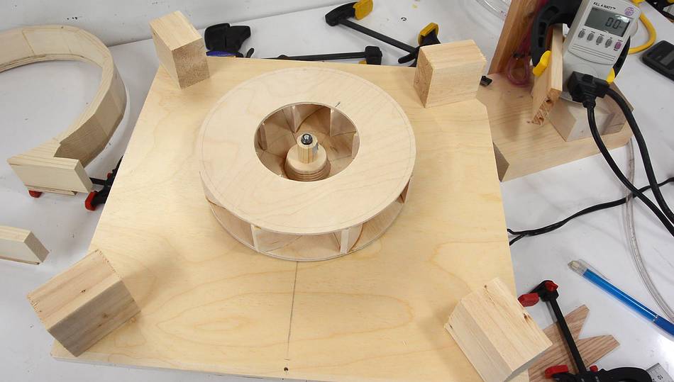
If more room around the housing helps, then what about way more room?
What If I get rid of the housing?
I used some blocks of wood to support the front panel, but the air could escape
in all directions.
Airflow increased to 13 m/s (a substantial increase over the 11 m/s), and the motor's
power consumption dropped from 146 watts to 137 watts. This would be a substantial
win! But measuring static suction, it was down to 8.8 cm (from 11.5 cm)
A wooden impeller spinning at high speed without any housing could be a bad idea.
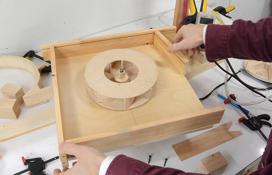
So my next experiment was to just have a rectangular box (as big as the plywood
I was using would allow).
Air flow was now 11.9 m/s (vs. 13 m/s for no housing) , and static suction 10.5 cm
(vs 8.8 cm for no housing). I then took off the incomplete side of the housing,
which increased airflow to 12 m/s and power dropped from 145 watt to 142 watt. Static
suction stayed the same.
I'm sure a rectangular housing is not ideal, but this suggests a generous sized housing
is beneficial.
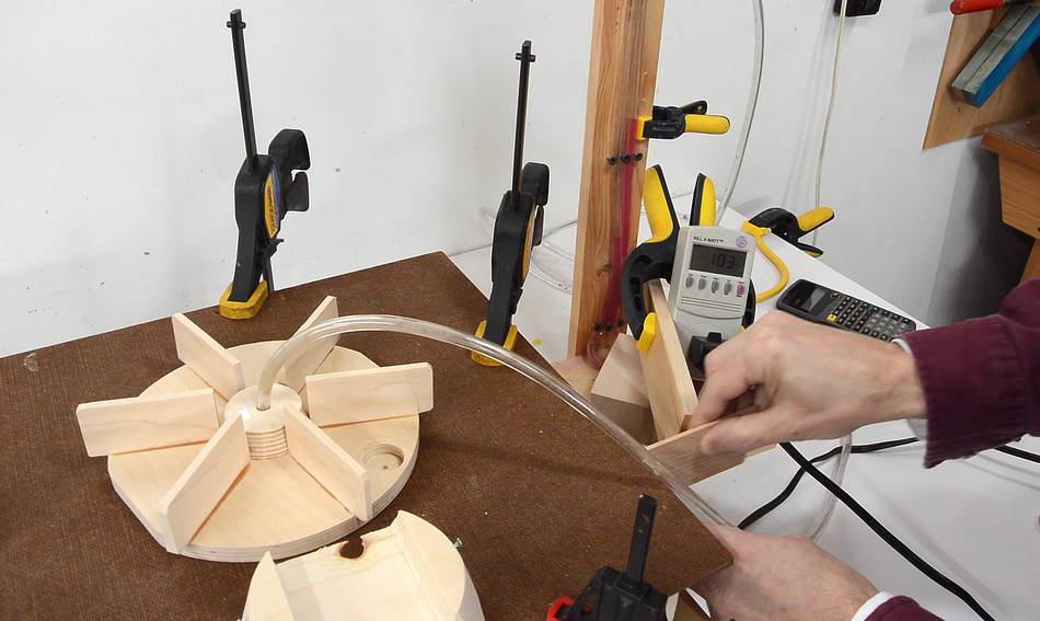
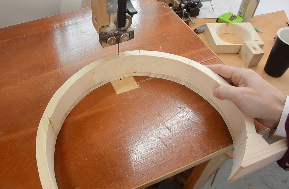
I made a few small cuts in the spiral housing to allow me to bend it open a bit
and re-tested. Air flow was 11.3 ms, and static pressure 11.5 cm.
So I still lost some static pressure vs the original housing, but gained some airflow.
It seems I can optimize for airflow or pressure, but not both.
In a dust collector, airflow is very much impeded by hoses, filters, possibly
a cyclone, and of course the woodworking machine itself.
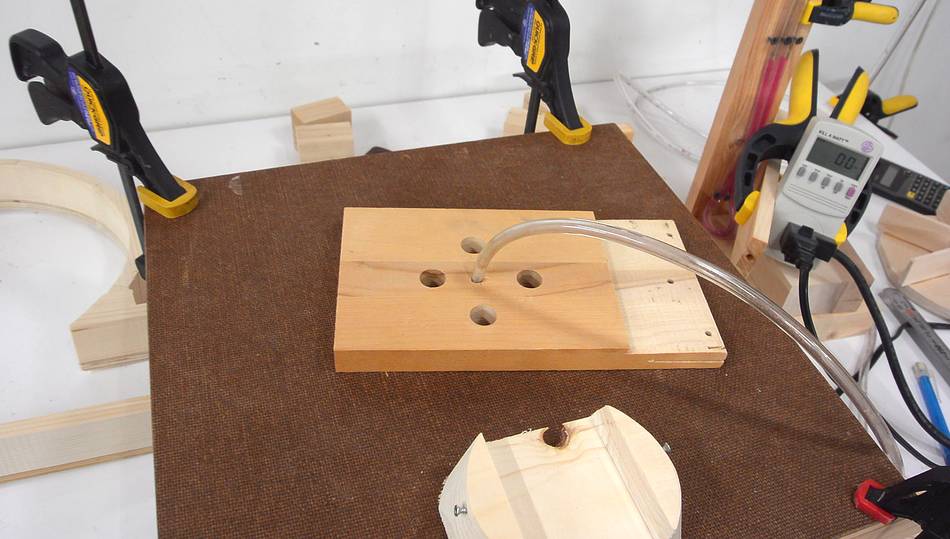
So I made this plate with four holes in it
to substantially impede the airflow while measuring suction (presumably the more
suction in this configuration, the more airflow). I re-tested
all my configurations with this. Results were:
Initial configuration: 9.8 cm, 114 watts
No housing: 7.3 cm, 120 watts
Rectangular housing: 8.8 cm, 119 watts
3-sided rectangular: 8.7 cm, 119 watts
Bent open spiral: 10 cm, 114 watts
The spiral housing performed best, maximizing suction while minimizing motor
power consumption. So even though the spiral didn't have the best airflow with
no resistance, I think for a dust collector, a spiral housing is best.
Housing shape
Air flow
Motor power
Pressure
Partly restricted pressure
Partly restricted motor power
Initial
11 m/s
146 watt
11.5 cm
9.8 cm
114 watt
Centered
10.5 m/s
145 watt
11.7 cm
No housing
13 m/s
137 watt
8.8 cm
7.3 cm
120 watt
Rectangular
11.9 m/s
145 watt
10.5 cm
8.8 cm
119 watt
3-sided
12 m/s
142 watt
10.5 cm
8.7 cm
119 watt
Bent-open spiral
11.3 m/s
146 watt
11.3 cm
10 cm
114 watt
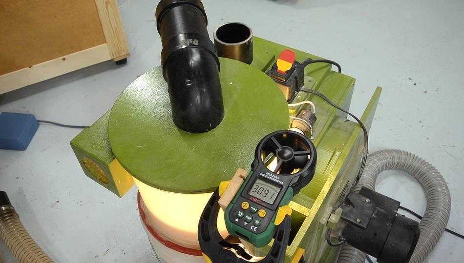
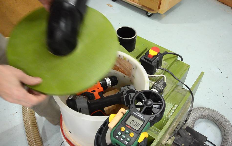
Just to illustrate how much airflow is impeded in a dust collector, I mounted
my anemometer over the exhaust of the dust collector blower.
With about 16' (5m) of 2.5" (63 mm) hose connected to the dust collector,
the air speed coming out was 7.6 m/s. Disconnecting the hose from the cyclone,
airflow increased to 10.4 m/s.
Then disconnecting the cyclone, airflow increased to 31 m/s!
I then put the plate with the four holes in it over the inlet, and air flow dropped
to 11 m/s. Still more than the initial configuration. So the four holes
present about the same amount of air resistance as the cyclone.
The biggest air resistance comes from the cyclone itself. And I'm sure some will suggest
that there is too much constriction of the airflow in the cyclone, but the inlets
and outlets are actually quite large.
It's the rapid swirling inside the cyclone
that makes for a lot of back pressure (the circulating air has a lot of centrifugal
force pulling it outwards, which makes for a large pressure differential).
To illustrate, I put some cordless drills in the cyclone to prevent the air from
circulating as much.
Air flow measured at the outlet increased to 20 m/s (but without the hose connected).
After that, I disconnected
the cyclone and hooked the 16-foot hose straight up to the filter box. Airflow was 8.9 m/s.
So the long hose has more air resistance than the cyclone.
An interesting thing about this set-up is that it could be analyzed like an electrical
circuit, with airflow as current, and pressure as voltage. But air
flow in a dust collector is turbulent (not laminar), so air resistance
(or pressure drop) is a function of air speed squared. However, air resistance
in the filter may only go up proportionally with flow rate (not flow rate squared),
because the flow thru the filter fabric is likely to be laminar. If you calculate
Reynold's number for the filter comes out to something small enough to suggest laminar
flow. I'd recommend reading a first year fluid dynamics textbook if
you want to analyze this sort of thing. Also look up
"Reynold's number"
But I hope this demonstration makes it clear that in a dust collector, a blower will
usually only move a fraction of the air that it would move with unimpeded airflow.
So the ultimate static pressure that the blower can produce is at least as
important as the blower's CFM rating (to a point, that is. An air compressor
will produce a lot of pressure but very little volume or CFM)
 I was using a dishwasher motor, about 0.1 hp, and I just happened to see another
dishwasher like that on the curb and took the motor out of that. The impeller
has backward curved vanes, which gives me added confidence
that that shape is best. And the housing was also roughly spiral shaped.
I was using a dishwasher motor, about 0.1 hp, and I just happened to see another
dishwasher like that on the curb and took the motor out of that. The impeller
has backward curved vanes, which gives me added confidence
that that shape is best. And the housing was also roughly spiral shaped.

 Comparing impeller shapes
 Blower design experiment
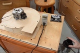 Box dust collector
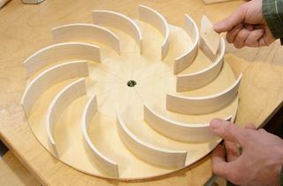 Dust collector blower
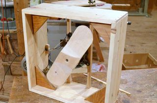 Building a box fan
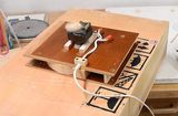 Mini dust collector
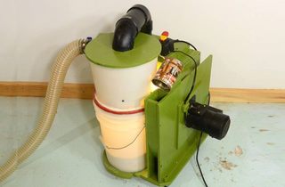 More about dust collection
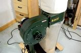 Cheap dust collector