Baby proofing a flower pot
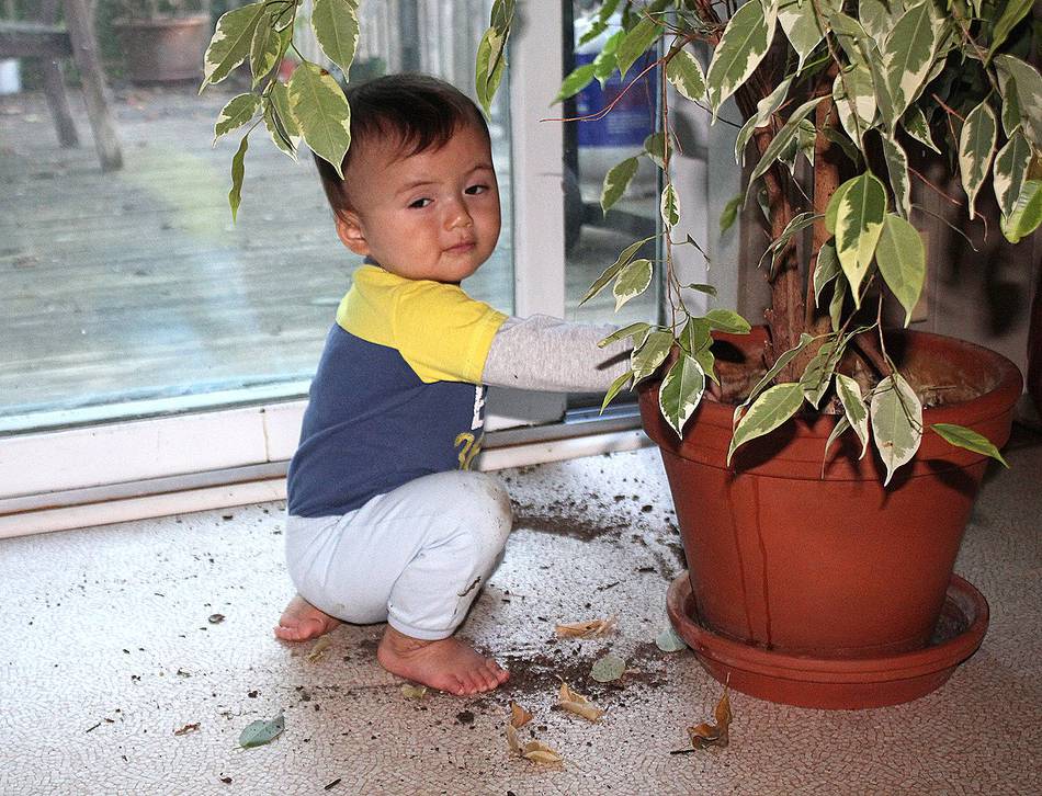 This project started with a simple problem: my nephew Max discovered how fun
it is to spread the dirt from the flower pot. How fun it is, to make
everything change colour! Not so fun for the parents though!
This project started with a simple problem: my nephew Max discovered how fun
it is to spread the dirt from the flower pot. How fun it is, to make
everything change colour! Not so fun for the parents though!
So Markus and I started musing about how best to put a screen on top. Not so easy with a clay flower pot.
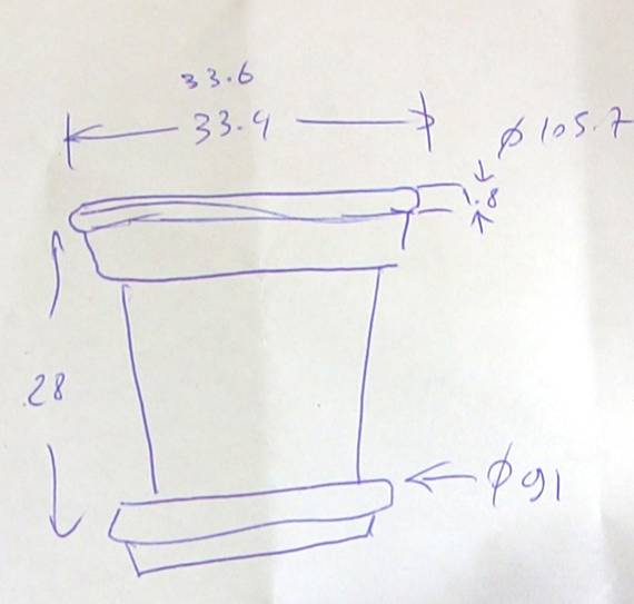 This gave me an idea.... So I started by taking measurements
of the flower pot.
This gave me an idea.... So I started by taking measurements
of the flower pot.
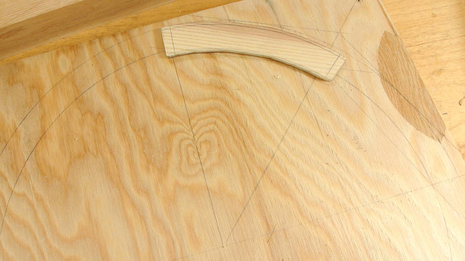 I wanted to make a hoop to go around the rim of the pot to hold a screen.
I figured I'd make it out of eight segments. Here's working out the
layout of it. I cut out a piece of wood to trace around for laying out
how to cut out the segments.
I wanted to make a hoop to go around the rim of the pot to hold a screen.
I figured I'd make it out of eight segments. Here's working out the
layout of it. I cut out a piece of wood to trace around for laying out
how to cut out the segments.
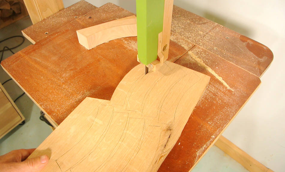 I laid out nine segments on 5 cm thick piece of oak, then cut these out on the bandsaw.
Why nine segments? In case I screw up one of them, of course.
 Checking the segments. So far so good, now to cut the finger joints.
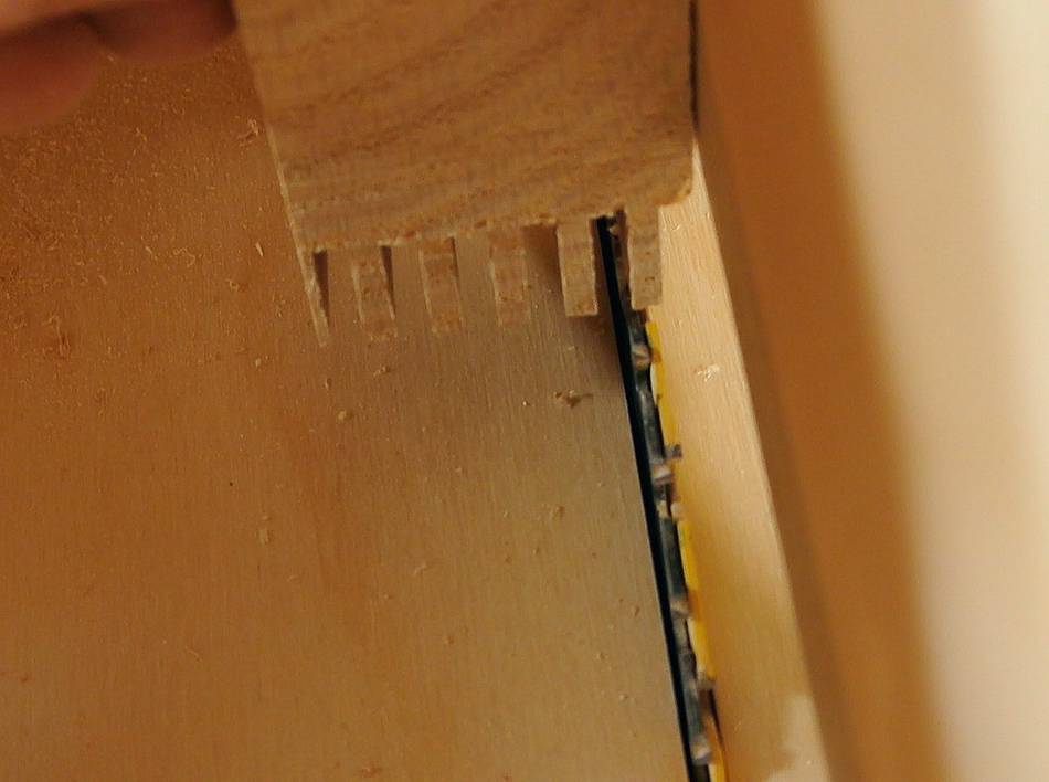
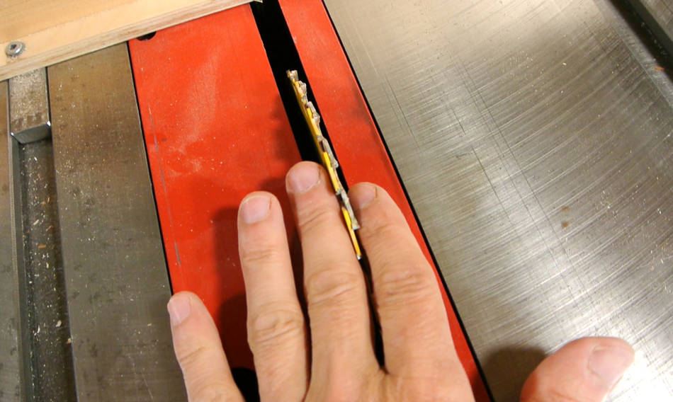 I stacked two 7 1/4" hand held circular saw blades in my table saw to get a
thicker kerf. That way, I wouldn't end up with fewer fingers in the joint.
I stacked two 7 1/4" hand held circular saw blades in my table saw to get a
thicker kerf. That way, I wouldn't end up with fewer fingers in the joint.
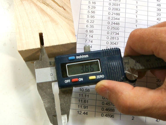 I made a test cut, and measured the width.
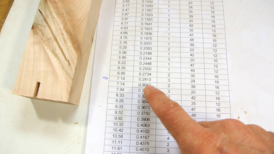 I need to move the stock by just under twice the width of that slot between cuts.
Here's looking up the next lowest increment on my spacing table. The spacing table
has all possible combinations of gears that I made for my
box joint jig.
I need to move the stock by just under twice the width of that slot between cuts.
Here's looking up the next lowest increment on my spacing table. The spacing table
has all possible combinations of gears that I made for my
box joint jig.
I'm sometimes asked where to get the spacing table. There's a small program included with the box joint jig plans to automatically generate a table based on how many gears of what sizes you have made.
I picked three turns of the 24 tooth gear against the 16 tooth gear for each advance. This will make joints a little looser than I was hoping, but it was the most suitable combination, and I didn't want to make another set of gears. In retrospect, I should have just switched to different blades to get a kerf that I could match more closely.
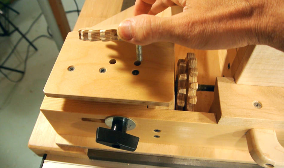 Installing the 16 tooth gear on the jig.
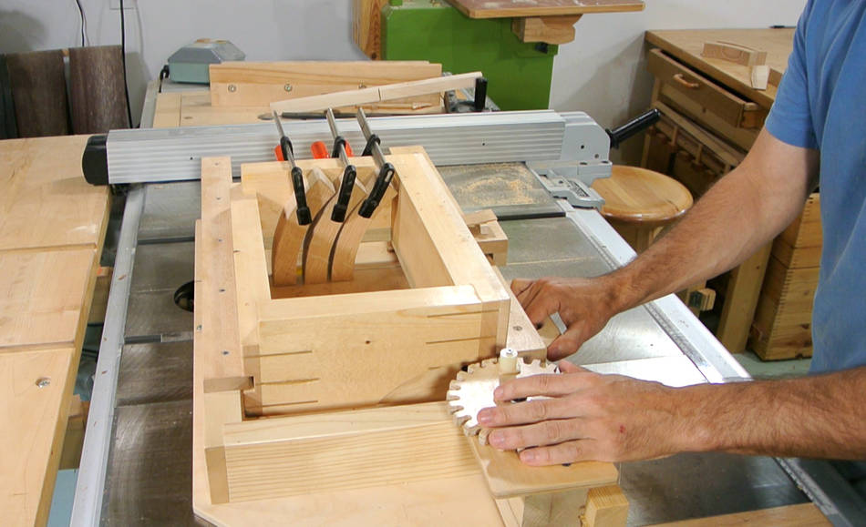 Three segments clamped to the edge of the jig. Three turns of
the crank between cuts. After six cuts, I return the carriage to the starting position by turning
the crank clockwise 3 x 6 turns. Though I don't actually count the turns when cranking it back.
I just turn it back so that the blade lines up with the first cut and the crank has the handle to the
left (what I consider "home position"). If I'm off by one crank turn, it's quite obvious.
Three segments clamped to the edge of the jig. Three turns of
the crank between cuts. After six cuts, I return the carriage to the starting position by turning
the crank clockwise 3 x 6 turns. Though I don't actually count the turns when cranking it back.
I just turn it back so that the blade lines up with the first cut and the crank has the handle to the
left (what I consider "home position"). If I'm off by one crank turn, it's quite obvious.
The other thing I do is to always approach the cut positions from the same direction. So when cranking the carriage "home", I crank half a turn past it, then back, so I approach home position from the same side. This because the threaded rod has some play (or backlash) with the nut. Always approaching it from the same direction cancels that out. The gearing has some backlash too, but that only makes up for a degree or two, much less effect than the play in the threads.
 I first cut all the "clockwise" ends of the segments. Next I set it up for the
mating cuts. I start by lining the blades with a finger of the pieces. I then
loosen the crank gear and re-engage it so this becomes my new crank-handle-to-the-right
home position.
I first cut all the "clockwise" ends of the segments. Next I set it up for the
mating cuts. I start by lining the blades with a finger of the pieces. I then
loosen the crank gear and re-engage it so this becomes my new crank-handle-to-the-right
home position.
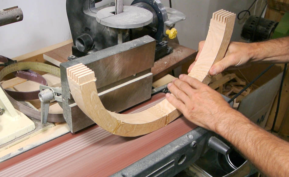
 Cutting the other segments. I realized my joints were going to be a bit loose, so I switched
to a slightly thinner stack of blades.
Cutting the other segments. I realized my joints were going to be a bit loose, so I switched
to a slightly thinner stack of blades.
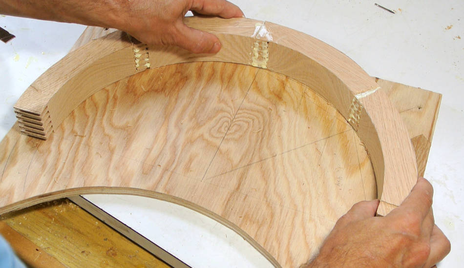
 Checking the segments on top of my layout.
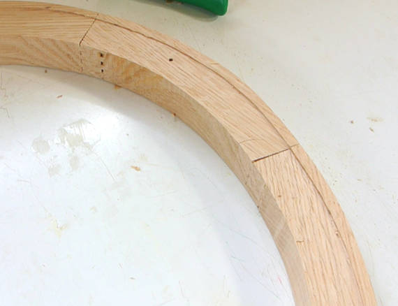
 The joints were less snug than ideal. I compensated by using lots and lots
of glue to fill the gaps. A relatively thick layer doesn't necessarily make for a weaker
joint. If anything, it might make for a stronger joint
(see here).
The joints were less snug than ideal. I compensated by using lots and lots
of glue to fill the gaps. A relatively thick layer doesn't necessarily make for a weaker
joint. If anything, it might make for a stronger joint
(see here).
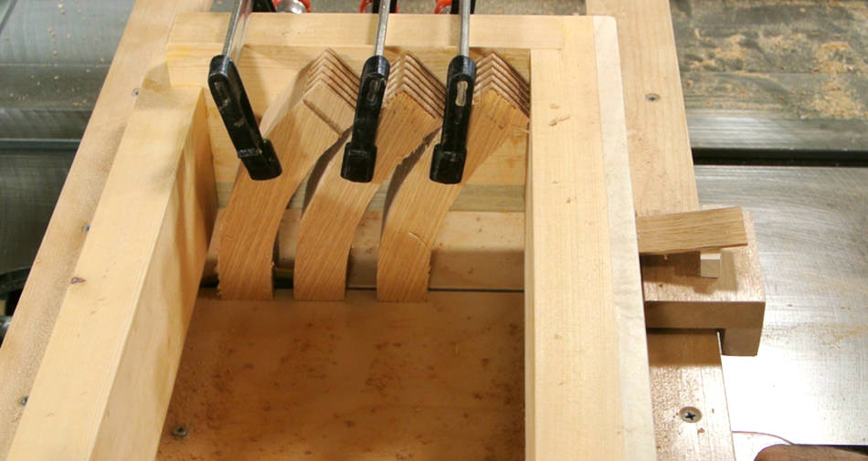
 With so much glue in the joints, they took a long time to dry, so I had
plenty of time to make sure the alignment matched my layout.
With so much glue in the joints, they took a long time to dry, so I had
plenty of time to make sure the alignment matched my layout.
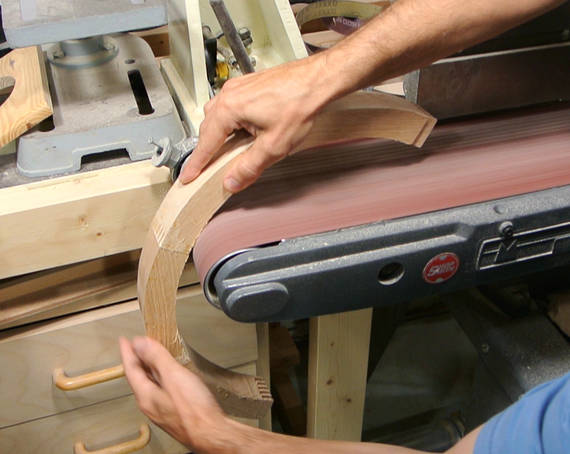 Sanding goes a long way to making imprecise joints look precise. I have heard it said:
"a grinder and paint, will make a welder what he ain't". For woodworkers, that would be
a sander and wood filler!
Sanding goes a long way to making imprecise joints look precise. I have heard it said:
"a grinder and paint, will make a welder what he ain't". For woodworkers, that would be
a sander and wood filler!
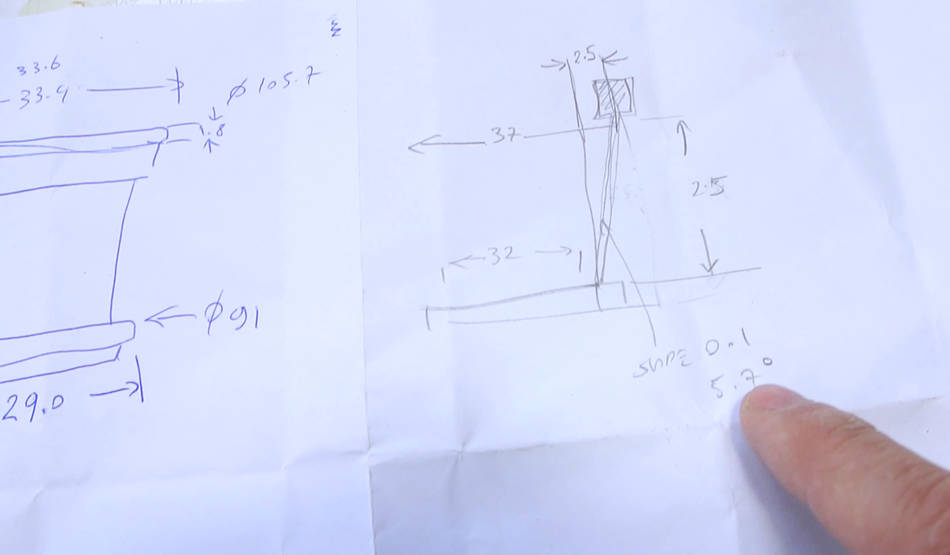 The hoop attaches to a base with dowels. Here, I'm working out the size of the base,
and what angle I will need for the dowels. The "slope" with respect to vertical for the dowels
needs to be 1 in 10. The inverse tangent of 0.1 is 5.7 degrees, so that's the angle I will need.
The hoop attaches to a base with dowels. Here, I'm working out the size of the base,
and what angle I will need for the dowels. The "slope" with respect to vertical for the dowels
needs to be 1 in 10. The inverse tangent of 0.1 is 5.7 degrees, so that's the angle I will need.
 Drilling the holes in the base.
 Next, using the hexagon of the base to figure out six hole positions.
with eight segments on the ring, mating with six dowels, and not wanting to drill
holes into the joints themselves, I had to be careful.
Next, using the hexagon of the base to figure out six hole positions.
with eight segments on the ring, mating with six dowels, and not wanting to drill
holes into the joints themselves, I had to be careful.
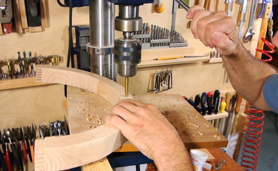 Drilling the holes in the ring pieces, also slanted 5.7 degrees.
 Before I fully glued the ring together, I took it over to my brother's for
a final fitting. Just to make sure the flower pot would actually fit inside. It would really
suck if it didn't!
Before I fully glued the ring together, I took it over to my brother's for
a final fitting. Just to make sure the flower pot would actually fit inside. It would really
suck if it didn't!
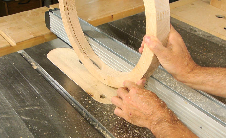 After that, I glued the ring together, then sliced about 1 cm off the top of it to make
a separate ring for clamping the screen on.
After that, I glued the ring together, then sliced about 1 cm off the top of it to make
a separate ring for clamping the screen on.
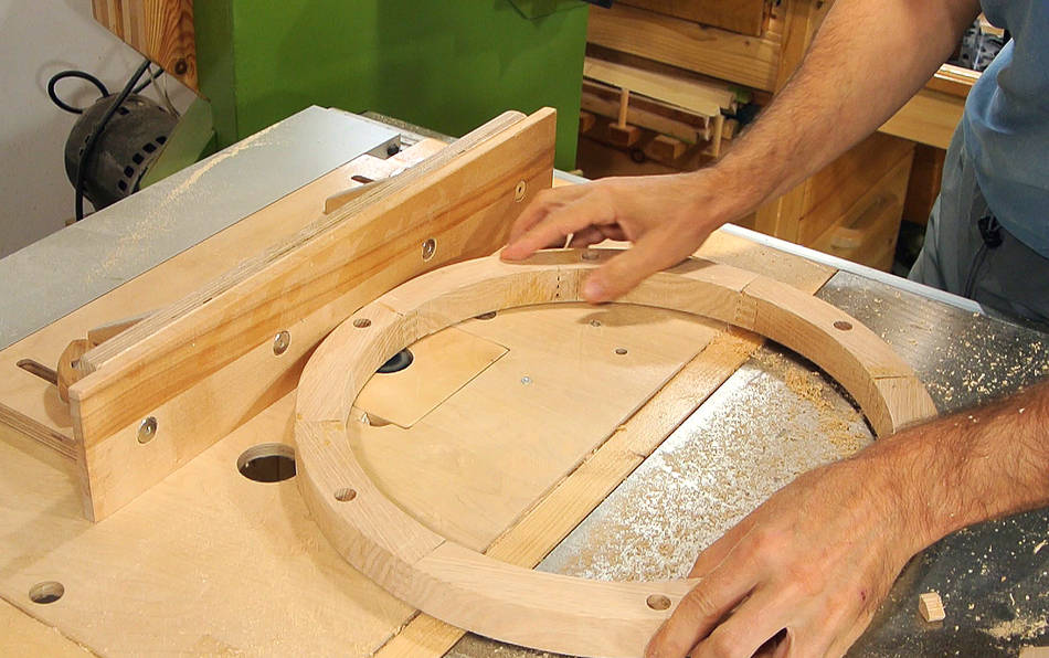
 I routed a wide and shallow groove into the inside top side of the main ring. This is
where the wire screen will fit in.
I routed a wide and shallow groove into the inside top side of the main ring. This is
where the wire screen will fit in.
 The wire screen needs to be made from two halves so it can fit around the tree.
Here's checking the fit.
The wire screen needs to be made from two halves so it can fit around the tree.
Here's checking the fit.
 Confident that it will all work, I'm gluing in the six dowels.
Homemade dowels, from matching wood, of course.
Confident that it will all work, I'm gluing in the six dowels.
Homemade dowels, from matching wood, of course.
 Now gluing it together with the base.
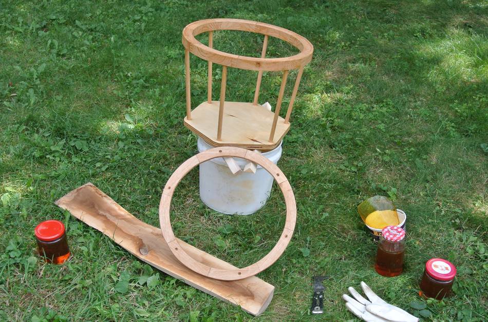 I varnished this base with polyurethane. I don't use oil based polyurethane much
these days, but I figured this contraption would get water spilled on it from
time to time, and the oil based varnishes are much better at repelling
water. I prefer to do polyurethane outside. It dries quicker outside,
and I don't get the smell in the house.
I varnished this base with polyurethane. I don't use oil based polyurethane much
these days, but I figured this contraption would get water spilled on it from
time to time, and the oil based varnishes are much better at repelling
water. I prefer to do polyurethane outside. It dries quicker outside,
and I don't get the smell in the house.
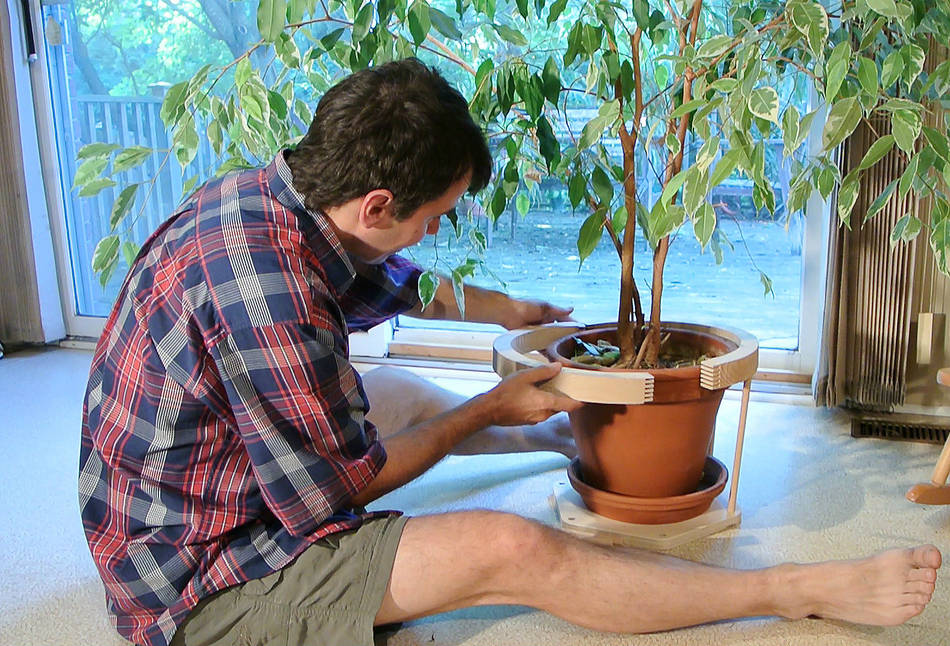
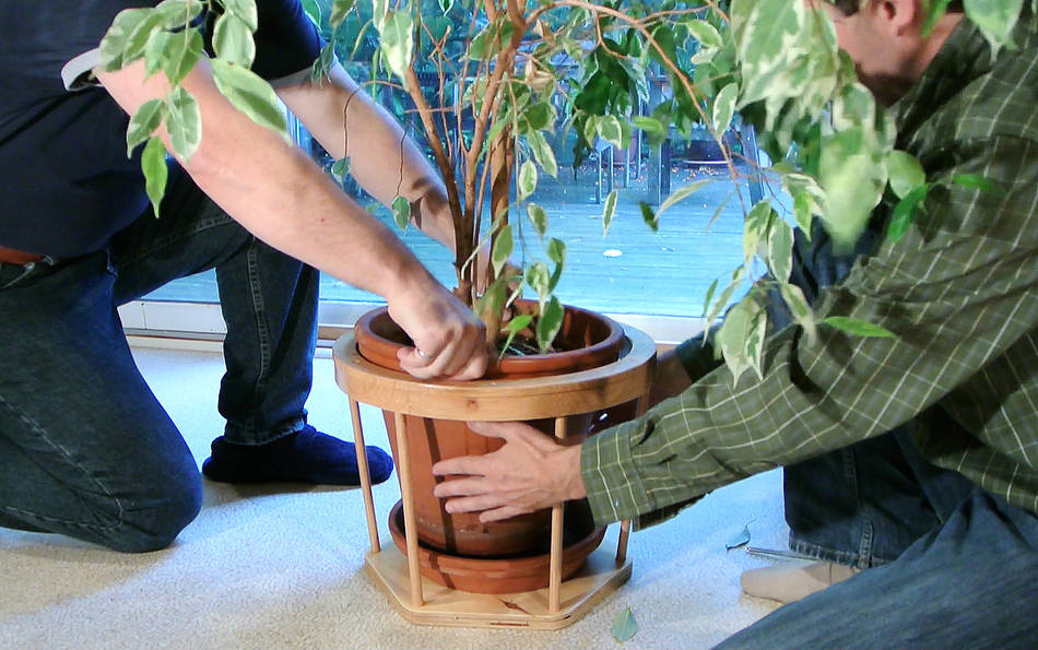 Inserting the flowerpot requires two people, one to lower the pot into it,
another to catch it below the rim and lower it onto the saucer.
Inserting the flowerpot requires two people, one to lower the pot into it,
another to catch it below the rim and lower it onto the saucer.
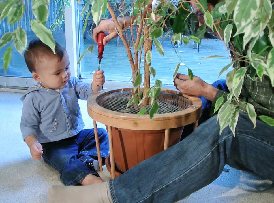 The installation of this contraption was interesting to max, especially
using the screwdriver.
The installation of this contraption was interesting to max, especially
using the screwdriver.
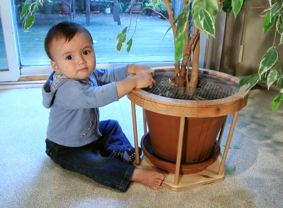 But with a screen preventing him from getting into the dirt,
the flowerpot lost most of its appeal.
But with a screen preventing him from getting into the dirt,
the flowerpot lost most of its appeal.
See also:
 Parallelogram baby gate
 Toddler stair handrail
 Corner shelf
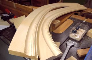 Making curved molding
 Wooden toys
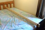 Bed baby fence
 Baby rocking machine