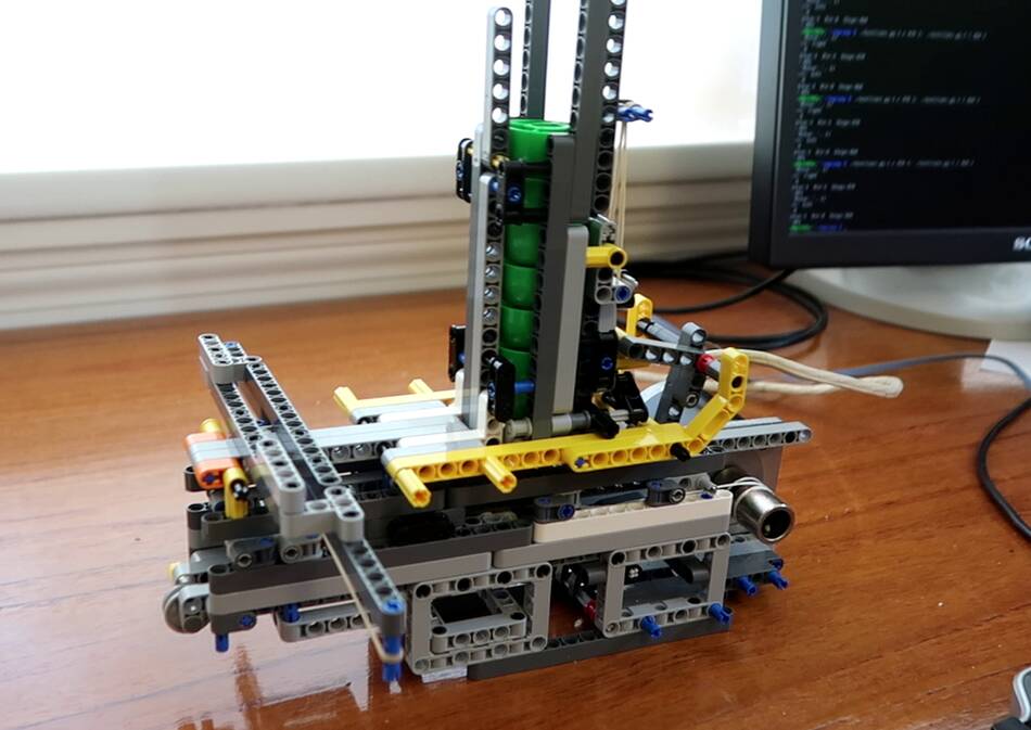
 I built this
repeating rubber band crossbow for shooting plastic caps a few weeks
earlier out of Lego.
My goal was to eventually make it so I could control and aim it by computer.
I built this
repeating rubber band crossbow for shooting plastic caps a few weeks
earlier out of Lego.
My goal was to eventually make it so I could control and aim it by computer.
I built this
repeating rubber band crossbow for shooting plastic caps a few weeks
earlier out of Lego.
My goal was to eventually make it so I could control and aim it by computer.
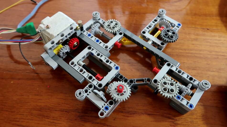
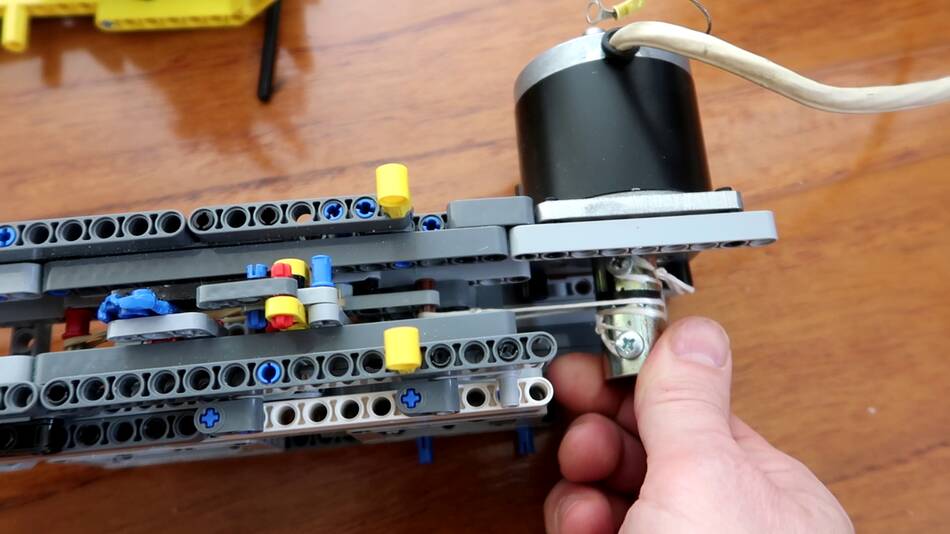 Originally the crossbow cocked by pulling a stick that stuck out
the back of it, but I changed it to a stepper motor for computer control.
Originally the crossbow cocked by pulling a stick that stuck out
the back of it, but I changed it to a stepper motor for computer control.
This motor came with a thick bushing on the shaft, and I wound a string around that shaft to pull the sled inside the crossbow. The sled has a hook that grabs onto the rubber band to draw it back.
As the motor turns, one string winds up, while the other string is unwound. One string pulls the sled directly, the other goes around a pulley on the front to move it in the opposite direction when the motor is reversed.
Once the sled has pulled the rubber band back, a mechanism on the bottom engages to briefly drop down the hook as it returns, releasing the rubber band.
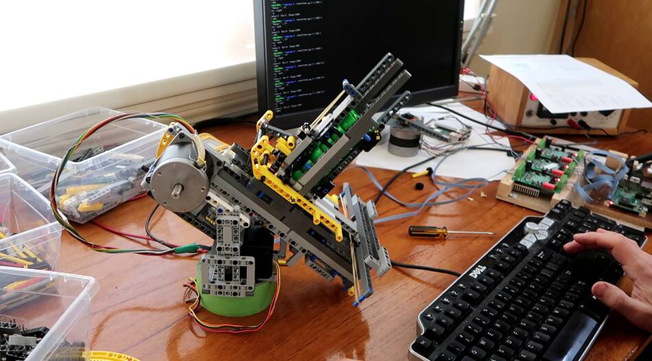
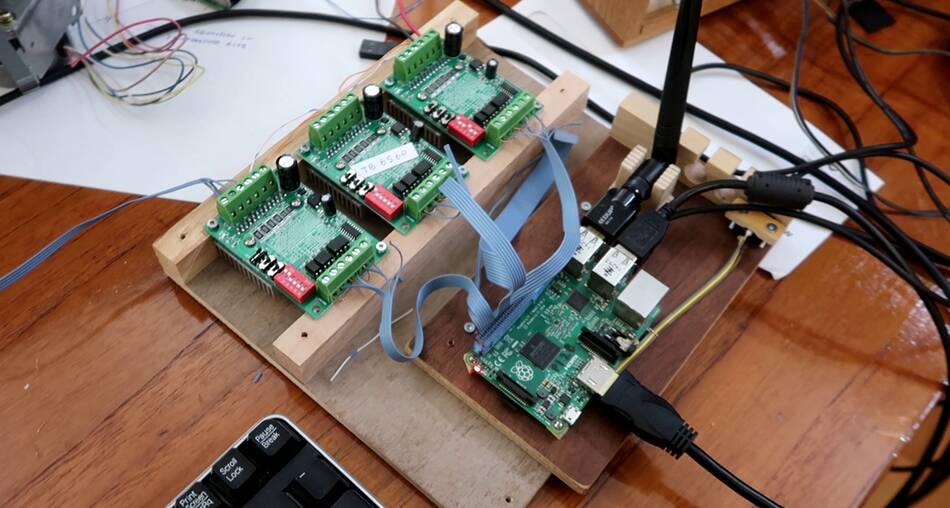 I hooked three stepper motor drivers to a Raspberry Pi computer
to control it. One driver is for the motor that draws the crossbow.
I hooked three stepper motor drivers to a Raspberry Pi computer
to control it. One driver is for the motor that draws the crossbow.
 I then did lots of testing with the motorized contraption to get it to work
reasonably well, though the whole mechanism is a bit flaky, and it would
jam roughly once every 20 shots.
I then did lots of testing with the motorized contraption to get it to work
reasonably well, though the whole mechanism is a bit flaky, and it would
jam roughly once every 20 shots.
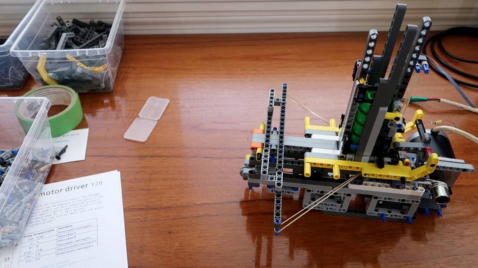
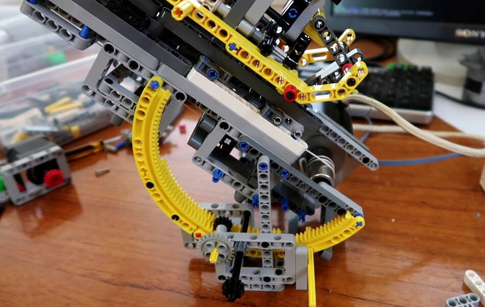 After that I started on a mechanism to allow the shooter to be aimed.
The center of mass of the whole assembly is quite far back because the stepper motor is much heavier than the Lego. I put the pivot very close to the center of mass. I used two segments of a large ring gear for the gearing to tilt the whole thing.
 I was able to fit a stepper motor for the tilt under the shooter, which
made the mechanism fairly compact. Everything will have to sit on another
big ring gear for swivelling.
I was able to fit a stepper motor for the tilt under the shooter, which
made the mechanism fairly compact. Everything will have to sit on another
big ring gear for swivelling.
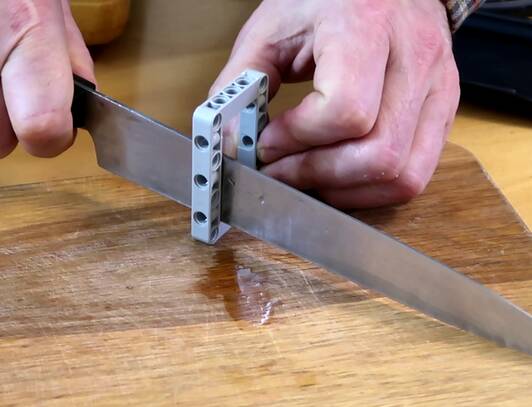 But the downward tilt angle was limited by the frames on the bottom of
the crossbow hitting the stepper motor. I couldn't think of a good substitute
for those frames because they are the only parts that have alternating
holes in different directions. So I just made a "custom" Lego part
by cutting a frame in half with a kitchen knife.
But the downward tilt angle was limited by the frames on the bottom of
the crossbow hitting the stepper motor. I couldn't think of a good substitute
for those frames because they are the only parts that have alternating
holes in different directions. So I just made a "custom" Lego part
by cutting a frame in half with a kitchen knife.
 And with the cut up frames substituted in, it can aim down
quite far, so far I had to raise the whole assembly up so the front
of the crossbow wouldn't hit the table.
And with the cut up frames substituted in, it can aim down
quite far, so far I had to raise the whole assembly up so the front
of the crossbow wouldn't hit the table.
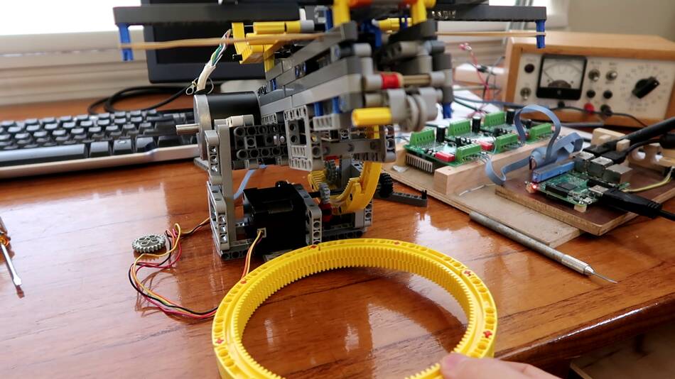
 I built this arrangement to support the large ring gear to allow the shoot and
tilt assembly to rotate on. Four gears, on edge, support the ring gear,
and four more gears run on the inside of the ring gear to guide it.
One of these is coupled to a stepper motor to turn the ring gear.
I built this arrangement to support the large ring gear to allow the shoot and
tilt assembly to rotate on. Four gears, on edge, support the ring gear,
and four more gears run on the inside of the ring gear to guide it.
One of these is coupled to a stepper motor to turn the ring gear.
 Testing the pan and tilt. The mechanism works. Now comes the task
of making all the software pieces work and work together.
Software is always the most time consuming part.
Testing the pan and tilt. The mechanism works. Now comes the task
of making all the software pieces work and work together.
Software is always the most time consuming part.

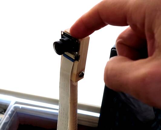 I bought a 120 degree fisheye camera module to hook up to the Raspberry pi
computer. The goal was to detect things with the fisheye lens and have
the cap shooter shoot at it.
I bought a 120 degree fisheye camera module to hook up to the Raspberry pi
computer. The goal was to detect things with the fisheye lens and have
the cap shooter shoot at it.
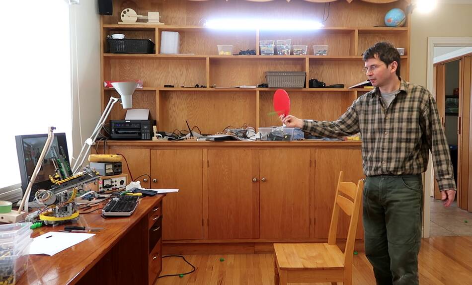
I want to eventually shoot at things based on motion, but for the time being I set the software to just find a red spot and aim for it.
The software is all mine - based on my imgcomp program I wrote years ago. So I had no need to lean how to use open CV or something like that.
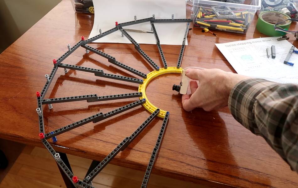
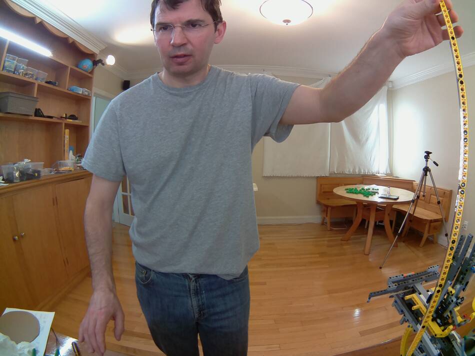 The fisheye lens causes some distortion, as you can see from the yellow Lego
assembly I'm holding at the right edge of the image. This Lego assembly is
straight in real life, but very curved due to lens distortion.
The fisheye lens causes some distortion, as you can see from the yellow Lego
assembly I'm holding at the right edge of the image. This Lego assembly is
straight in real life, but very curved due to lens distortion.
 I need to correct for that geometry. My first assumption was that the fisheye
lens had a linear relationship between angle from the center of the lens and
number of pixels from the center of the lins in the image. Or at least,
such a mapping would produce a nice fisheye image, and my initial implementation
of the geometry conversion was based on that.
I need to correct for that geometry. My first assumption was that the fisheye
lens had a linear relationship between angle from the center of the lens and
number of pixels from the center of the lins in the image. Or at least,
such a mapping would produce a nice fisheye image, and my initial implementation
of the geometry conversion was based on that.
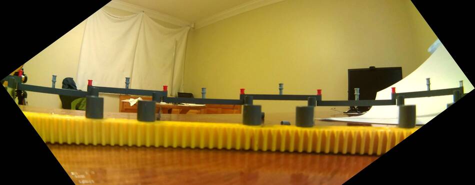
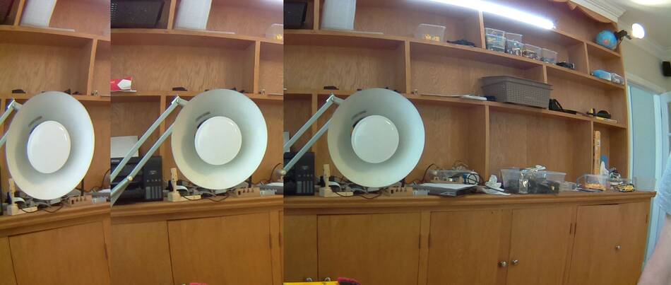 But then I did a quick test, just looking at the desk lamp while rotating the camera.
If my assumption were correct, the width of the lamp should not change as I rotate the camera away from the lamp, so the image of the lamp moves towards the edge of the image. But as you can see from this composite image, towards the edge, the image of the lamp is squished.
 Of course, any lens will produce an image that is in some ways distorted, because
what the lens sees is essentially part of the inside of a sphere, or hemisphere, and
it needs to map that to a flat image.
Of course, any lens will produce an image that is in some ways distorted, because
what the lens sees is essentially part of the inside of a sphere, or hemisphere, and
it needs to map that to a flat image.
I wanted to characterize the distortion of the lens, so I needed some markers precisely spaced at constant angles from the lens to photograph. I built a big protractor out of Lego that I could put the lens in the middle of.
 I angled the camera so that the protractor was diagonally across it's view.
That way I could calibrate the lens distortion all the way into the corners.
I then rotated the image so that the protractor made a horizontal line and
measured the X-coordinate of every pin in the photo.
I angled the camera so that the protractor was diagonally across it's view.
That way I could calibrate the lens distortion all the way into the corners.
I then rotated the image so that the protractor made a horizontal line and
measured the X-coordinate of every pin in the photo.
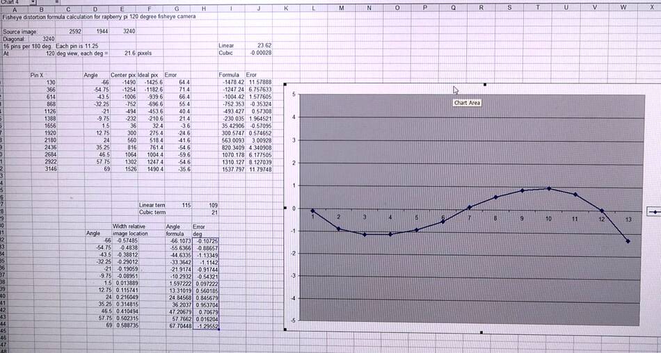 I then graphed the angle error (with respect to the assumption that each degree was
a fixed number of pixels) and graphed that in a spreadsheet program. By adding
a cubic term, I was able to produce a simple polynomial that matched the measured
angles within half a degree across the lens. I figured that was close enough
because my cap shooter doesn't shoot that accurately anyway.
I then graphed the angle error (with respect to the assumption that each degree was
a fixed number of pixels) and graphed that in a spreadsheet program. By adding
a cubic term, I was able to produce a simple polynomial that matched the measured
angles within half a degree across the lens. I figured that was close enough
because my cap shooter doesn't shoot that accurately anyway.
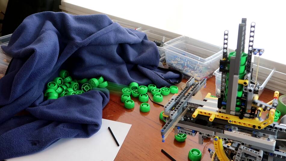
 I still had some reliability problems with my cap shooter mechanism, so the next
step was to shoot it a few hundred shots, aimed at a fleece sweater, to see just how
it jammed or misfired and make corrections. With a few tweaks here and there,
I was able to improve the reliably a fair bit.
I still had some reliability problems with my cap shooter mechanism, so the next
step was to shoot it a few hundred shots, aimed at a fleece sweater, to see just how
it jammed or misfired and make corrections. With a few tweaks here and there,
I was able to improve the reliably a fair bit.
 Then more software work. With the lens distortion formula, I was able to turn
the fisheye coordinates to coordinates to ones a rectilinear lens would produce,
which I then turned into pan and tilt, involving more geometry conversions.
Then more software work. With the lens distortion formula, I was able to turn
the fisheye coordinates to coordinates to ones a rectilinear lens would produce,
which I then turned into pan and tilt, involving more geometry conversions.
Much of that geometry conversion could have been avoided if the lens was just mounted to the cap shooter and swivelled with it, but that introduces its own set of problems, especially if I want to eventually have it trigger on things moving -- because detecting specific things moving in a picture is really hard if the whole picture moves!
With the software set to detect and aim at a red spot, I did lots of testing holding a red piece of cardboard and having the cap shooter shoot at it.
 Plastic caps were scattered all over the room.
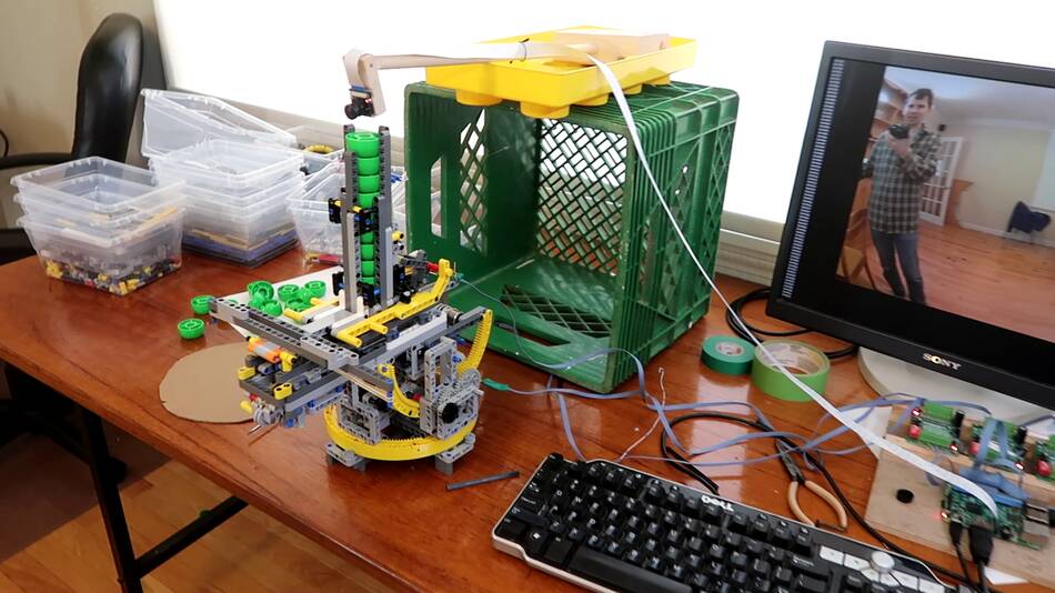 My next optimization was to mount the camera directly above the cap shooter,
supported by a milk crate. This helps cut down on parallax errors -- which,
of course, could be avoided if the camera was mounted on the cap shooter itself.
My next optimization was to mount the camera directly above the cap shooter,
supported by a milk crate. This helps cut down on parallax errors -- which,
of course, could be avoided if the camera was mounted on the cap shooter itself.
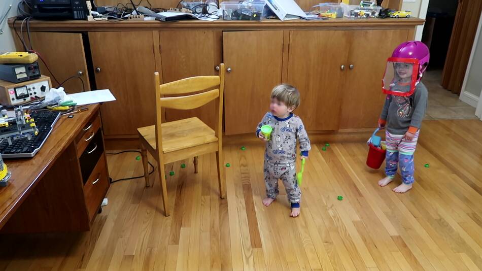
 The kids, especially Kurt, were always fascinated by my cap shooter,
and also the previous machine catapult, so I figured they
would enjoy this contraption. But I didn't want them to get shot at in the eye,
so I made a screen visor for Harriet's bicycle helmet, and changed the software
to aim for purple things instead. But the kids enjoyed this less than I
anticipated. Maybe getting shot at isn't as fun as I thought it was.
The kids, especially Kurt, were always fascinated by my cap shooter,
and also the previous machine catapult, so I figured they
would enjoy this contraption. But I didn't want them to get shot at in the eye,
so I made a screen visor for Harriet's bicycle helmet, and changed the software
to aim for purple things instead. But the kids enjoyed this less than I
anticipated. Maybe getting shot at isn't as fun as I thought it was.
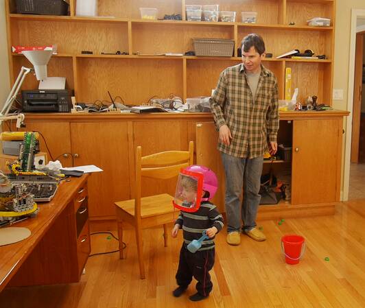
Worse yet, when I put the helmet on Kurt, he took it off, while the system was still primed and loaded. Holding the target in front of your face isn't necessarily a good idea!
The whole project took a long time to build. I have been thinking of getting back into working on high tech, so doing a high-tech project of moderate complexity for fun is a good way of seeing whether I can still do it, or want to do it.
A few weeks after I built it, I modified the software to optimize for aiming at squirrels and set it up on the patio outside. I figured this would be a fun thing to try. But leaving it set up all day, only one squirrel showed up briefly, and it ran away as soon as the shooter panned towards it, so my contraption never got to take a shot. The forecast was for rain overnight, so I didn't leave it set up to try again, and I never got around to trying it again.
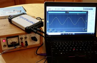 Reviewing the chepest USB scope I could find online (video only)
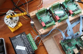 Stepper mictostepping from Raspberry Pi (video only)
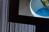 My imgcomp program (motion triggered time-lapses)
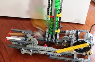 Lego machine catapult
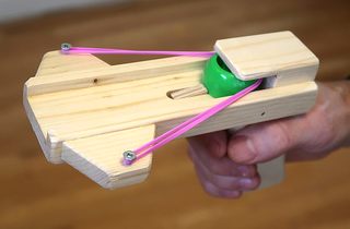 Wooden plastic cap shooter build
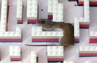 Mouse in a Lego maze
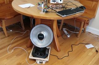 High-tech automatic infrared heater aimer
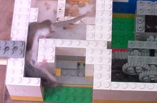 Mouse gap squeezer teaser machine
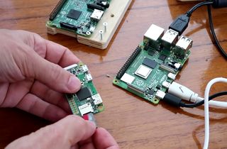 Making headless Raspberry Pi blink assigned IP address
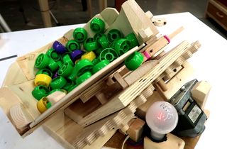 Automatic hopper fed catapult
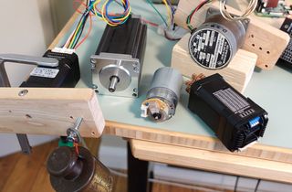 Closed loop stepper motors -- very impressive