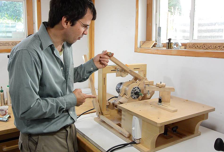
Why the pantorouter XL?
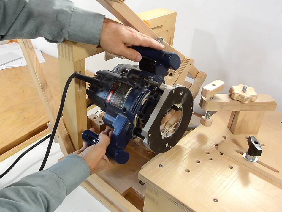
A frequently asked question from readers wanting to build
the pantorouter is where to get that style of router. This style
of router, with a motor that pulls out of interchangeable bases
(like this one)
is hard to find outside of North America. This
is probably because other countries require that the router turn off when you
let go of the handle, and that necessitates putting the switch on the handles,
and that's difficult to do with the motor detaching from the base and handles.
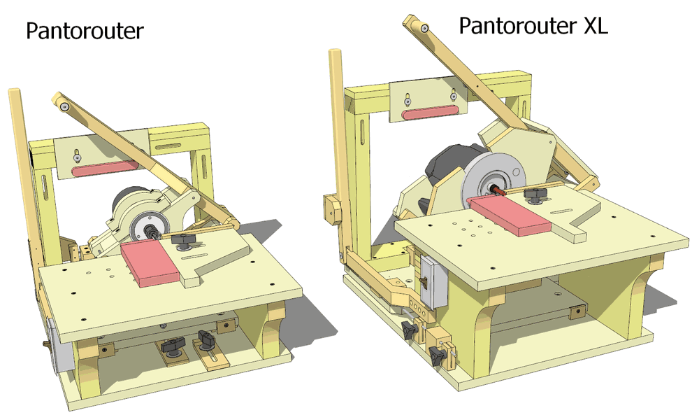
Outside of Canada and USA, except for a few brands and models, routers
are plunge routers, with the body and handles often
consisting of one piece. This type of router is too bulky to fit
into the pantograph mechanism of my original pantorouter design.
So I designed the "Pantorouter XL", which has a larger pantograph
mechanism for mounting a plunge router, complete with handles,
in the pantograph.
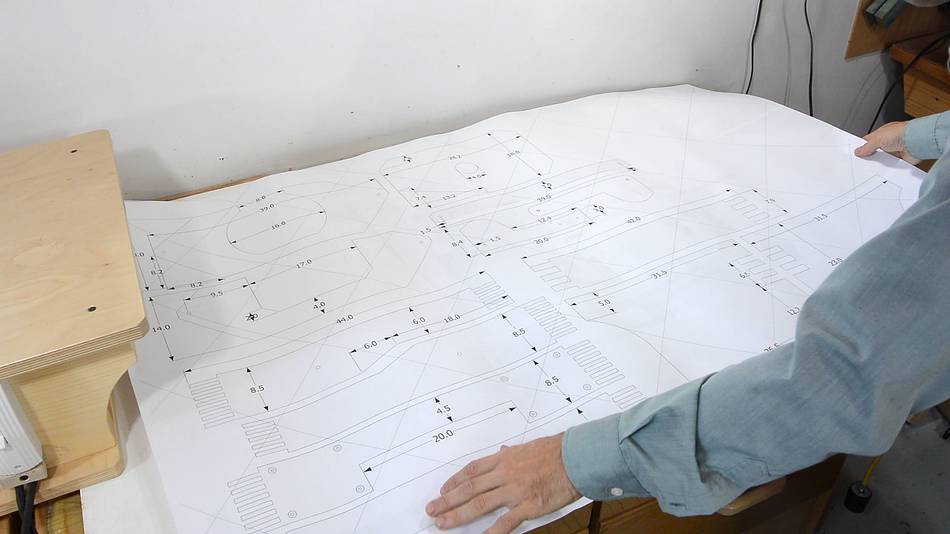
Building the pantograph
I printed out my plans, including a sheet (pasted together from many pages)
with a lot of the parts in full size
using my BigPrint program.
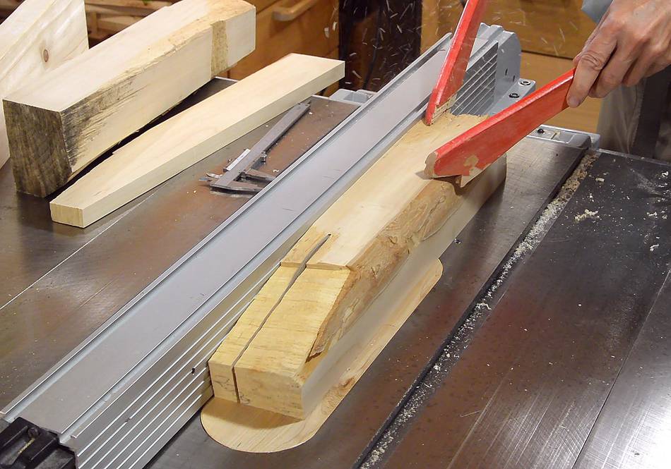
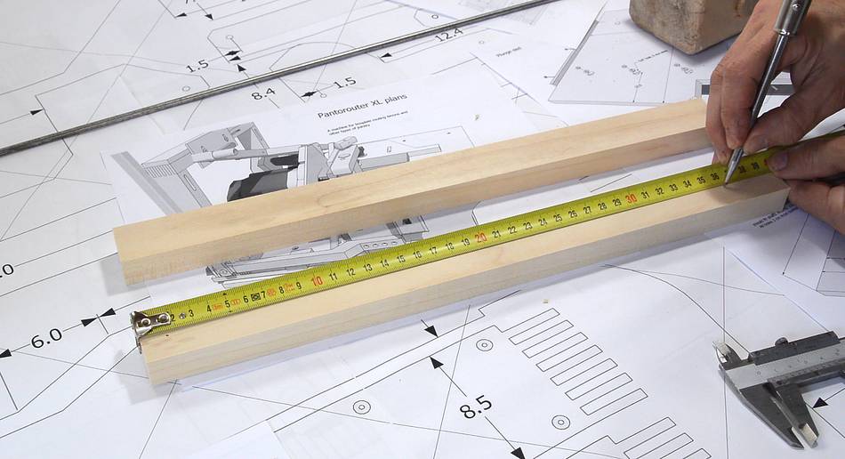
The long parts of the pantograph link are made from hard maple. Here,
I'm cutting the parts out of a piece of firewood.
Marking where the holes need to end up. These measurements
are very critical.
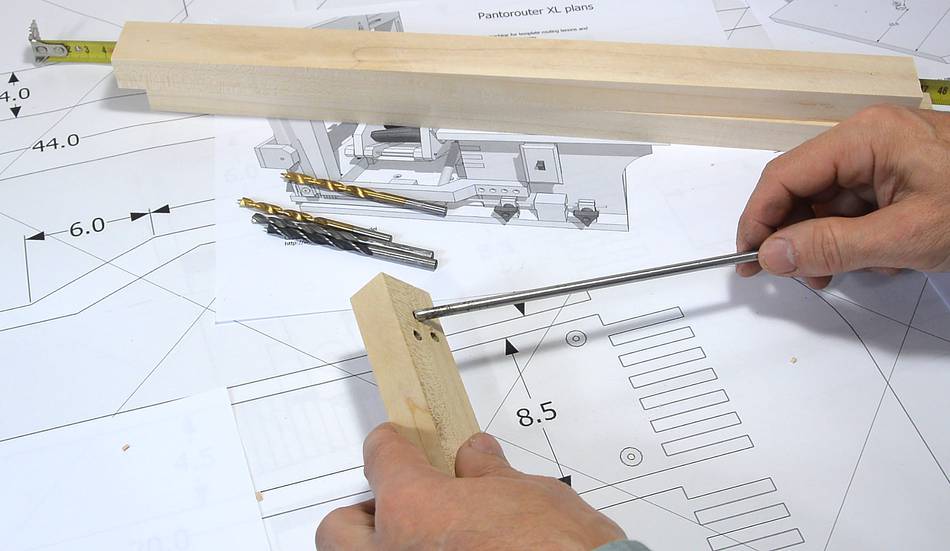
The links will pivot on some 3/16" (5 mm) steel rod. Getting holes
of just the right fit is important. I drilled some test holes with
different 3/16" brad point bits, but these all drilled slightly
oversized, resulting in a fit that had a tiny amount of play in it.
I ended up drilling the holes at 11/64 (1/64" or 0.4 mm smaller than I
needed), and then drilling the holes to final size using a regular
(not brad-point) drill bit.
This resulted in a very tight fit with the rod, which is what I was
aiming for.
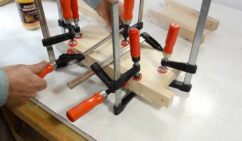
Starting to assemble the links.
Freshly applied glue is very slippery, so to keep parts aligned, I clamp
on one of the long pieces to the plywood without any glue,
then apply glue to the thinner bottom layer...
... and glue on the next (18 mm) thick layer, using the clamped-only
piece to help align it.
Next I glue on the other long piece of hardwood.
I gave it a few minutes, the glue on the first joint set sufficiently
to no longer slide around. Then I removed the first (clamped but not
glued) piece of hardwood, and clamped on the second piece.
I wanted to remove that first piece of hardwood, otherwise, the glue
that squeezed out from gluing on the plywood would have made it very
difficult to remove later.
With the glue dry enough, I can now glue on the other rail to the
pantograph links (the rail that I initially only clamped but not glued on).
It's very important that the pieces align laterally. Here, I'm checking
that alignment with a square.
Rather than follow the dimensions in the CAD drawing, it's best to use the
geometry of your router base instead. This will make it easier to fit the
router later.
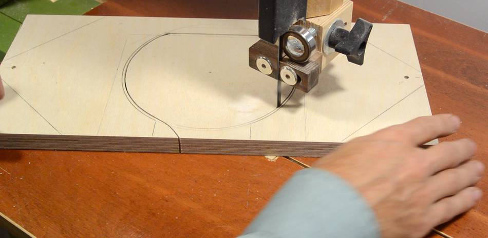
Cutting out the pieces on the bandsaw.
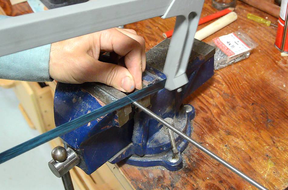
Cutting up some pieces of 3/16" (5 mm) steel rod for the pivot pins.
With the pins fitting in the links very tightly, I made a sort of reamer
out of a piece of the steel rod, by cutting a lengthwise slot near the end
with a hacksaw.
I then used that steel rod in a drill to expand the holes for a very snug and only
slightly tight fit.
The holes are not necessarily perfectly aligned with each other, so I take the
reamer, push it through the hole on one side, and then into the hole on the
other side. I do this coming in from both sides to get both holes into
alignment.
A number of people have "improved" on my design by drilling larger holes and
using bronze bushings in the holes. But that means you can't use this trick
to get the holes fully aligned. The bronze bushings do last longer. A steel
rod in a wooden hole might wear out after cutting as few as ten thousand joints.
But if you are at all concerned about wear, put oil in the holes and polish the
rods, and it should last much longer.
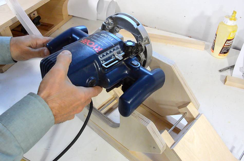
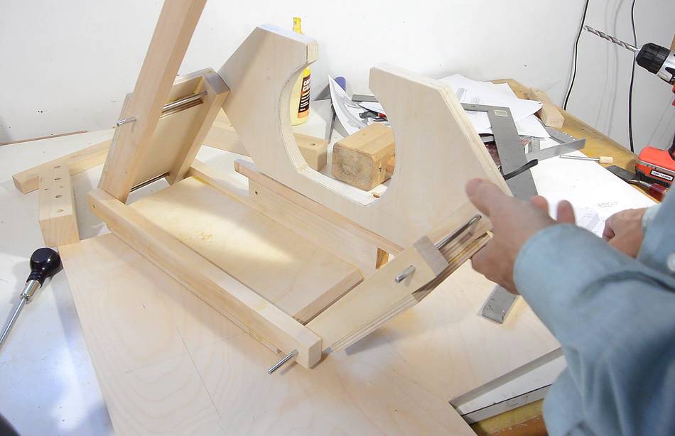
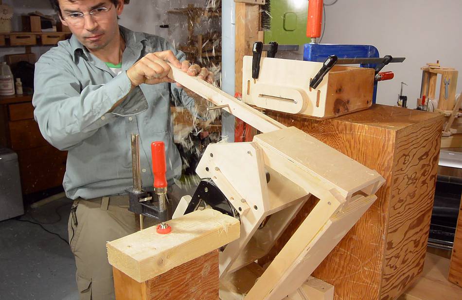
First test assembly of the pantograph mechanism.
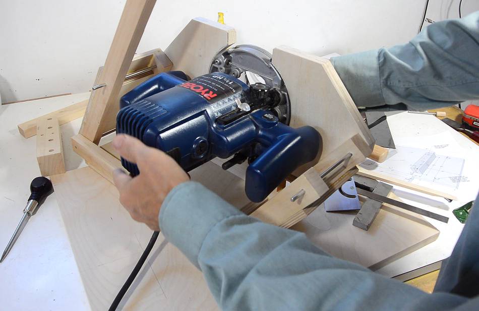
Fitting that blue Ryobi plunge router is a challenge. The handles are
not detachable and very bulky. I first thought it wouldn't fit (with
the pantograph tilted by just over 45 degrees from square).
But then I realized, in my design, the pantograph
only needs to tilt by 30 degrees off square. Here I added some blocks
of wood below the router mount to limit the tilt to just over 30 degrees
off right angle.
At that tilt angle, the handles do not
interfere with the links - though they do interfere with the back
plate.
The pantograph needs to be mounted on a base, and the base has two corners cut
away to fit in the machine, as designed. I mostly cut these on the table saw, then
finished the corner cuts on the bandsaw.
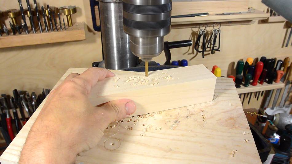
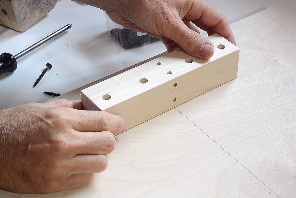
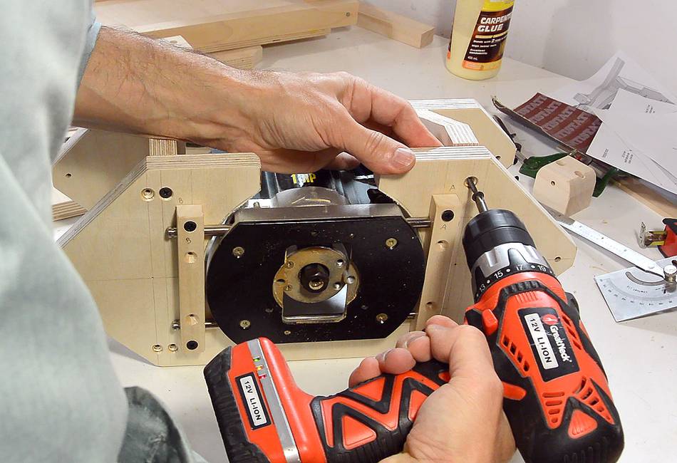
Drilling the holes in the mounting blocks for the pantograph.
These need to be very square. To compensate for any non-square-ness that my drill
press may have, I drill the hole about 5 mm in then rotate the block 180 degrees
(around the axis of the drill bit) and drill another 5 mm, repeating until
I'm all the way through. If the drill press table has any tilt error, every
180-degree rotation effectively reverses that.
But one of the holes was still not quite square. The piece did not lie flush
against the pantograph link once it was on the shaft. So I drilled another hole,
and another, and by the fourth hole, I had one that was sufficiently square.
I think the grain of the wood, running diagonally, pulled the drill to the
side a little.
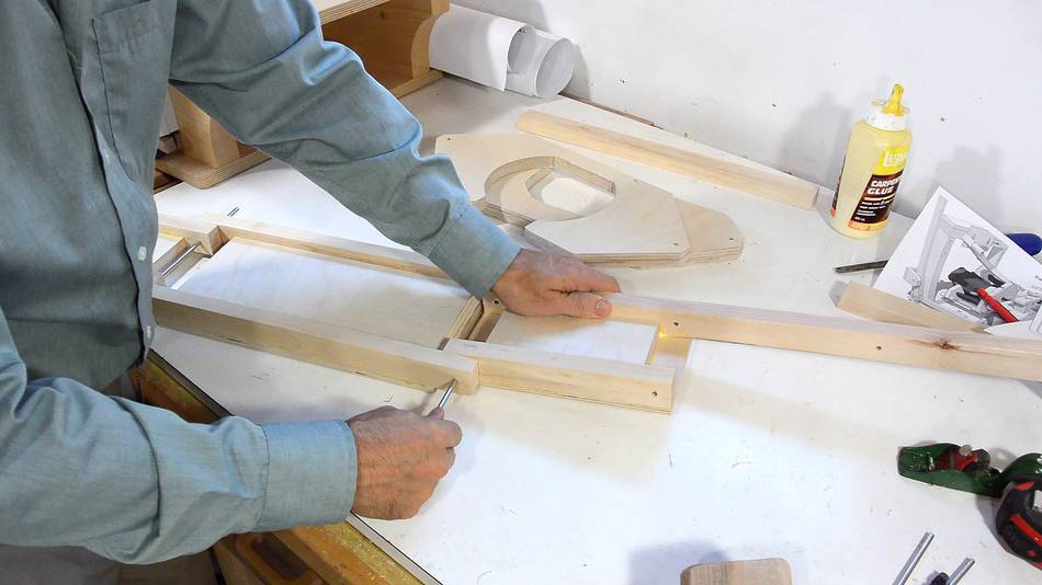
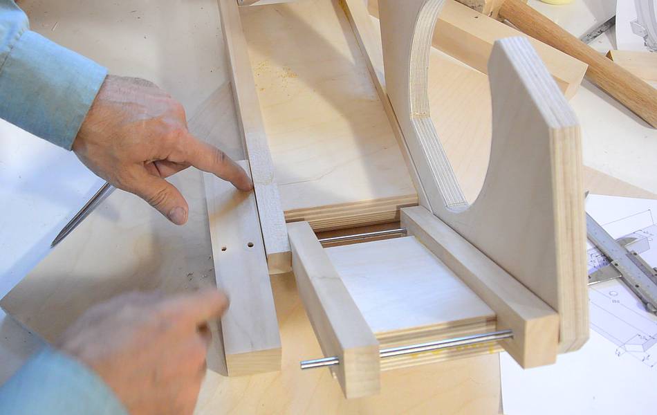
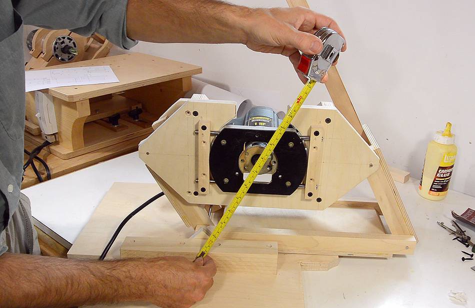
I have to make sure the axis of the pantograph is exactly square to the back and parallel
to the sides. I start by marking a line square to the back edge.
A pencil mark, directly below the hole, on the link, allows me to line it up.
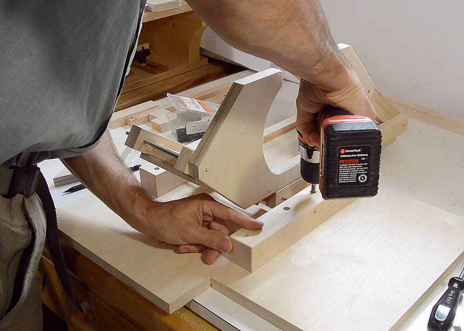
I then mark the hole locations by inserting screws in the holes, and tapping them
down with a hammer. The point of the screws makes a divot in the wood to mark
where to drill the pilot holes.
Getting the location for the front mount. I used two scraps of 18 mm birch
plywood as spacers behind and in front of the pantograph to leave sufficient
room for the spring cams that will help compensate for the weight of the router
later.
I lined up the front mount to the pencil line the same way as the back one.
Then, inserting screws in the holes, and tapping the screws with a screwdriver
and hammer, I mark the pilot hole locations.
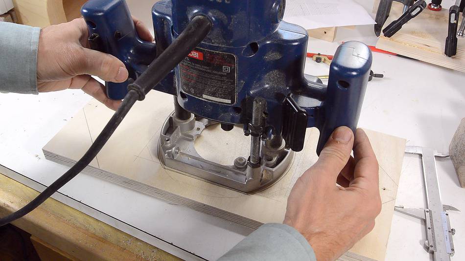
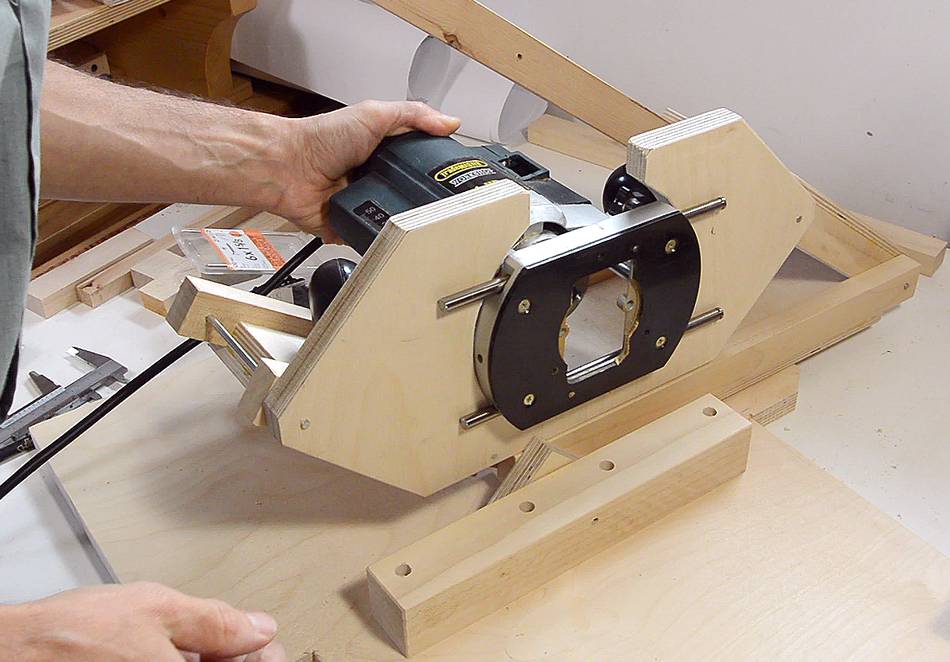
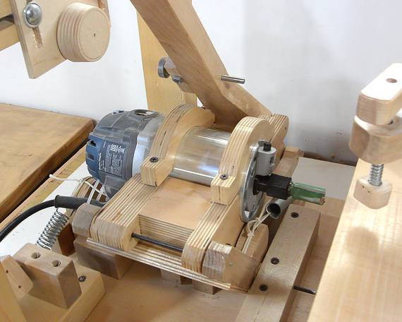
Mounting the pantograph.
Although the Ryobi router would fit, I used another plunge router with
a broken switch. With a broken switch, that router wouldn't be of much
use for other jobs anymore.
Most people mount routers in jigs by screwing the base to a piece of
plywood. This method would work for this mount as well, but I'd lose a little bit
of depth of cut. So instead, I'm mounting it by two metal rods. Nearly all router
bases have holes for two metal rods, for use with various jigs.
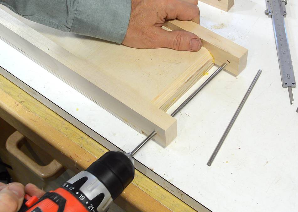
The metal rods need to be mounted to the front of the router mount.
I drilled holes in two pieces of wood exactly the right distance
for the two rods.
After that, I slice off part of the blocks, so that I have about 0.5 mm
of the hole cut away.
I used a compass to mark the same distance from each hole to make sure I had the
center between the two holes, then lined that up with a center line
on the front mount. This will ensure that the router's collet will end up
on the center line between the two pivot points.
I put screws in the screw holes, tapped them with a hammer, then used the divots
from that to drill pilot holes for the screws in the plywood.
This mounts the router securely to the front part of the mount, but I need support
to keep the front from pivoting. So I made some pieces
of plywood that reach around the router's handles. With this router,
I could have just unscrewed the handles as well.
Screwing the pieces together.
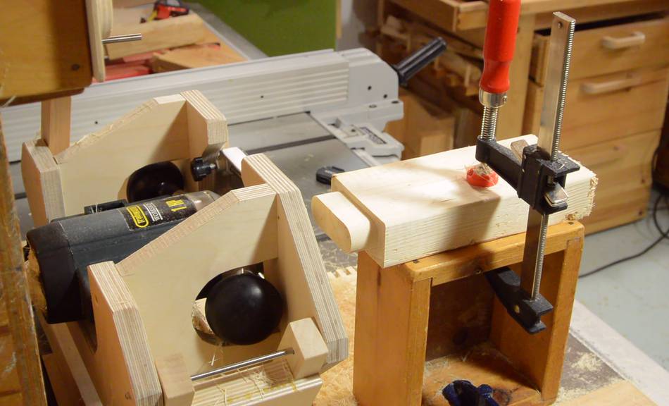
Now installing the router mount in the pantograph.
It turns out, the pieces of plywood to link the front and back hit the
pantograph links, and I couldn't quite tilt it 30 degrees off-square.
But I was only a little bit off, so just chamfering the edges of the
plywood pieces that hit the links allowed me to get 30 degrees tilt again.
I'm still missing the template holder, stock holding table, plunge
mechanism, and other bits. But the pantograph is the core of
the machine, and I was keen on trying it out. So I used some
wooden boxes to hold the template and stock.
 A frequently asked question from readers wanting to build
the pantorouter is where to get that style of router. This style
of router, with a motor that pulls out of interchangeable bases
(like this one)
is hard to find outside of North America. This
is probably because other countries require that the router turn off when you
let go of the handle, and that necessitates putting the switch on the handles,
and that's difficult to do with the motor detaching from the base and handles.
A frequently asked question from readers wanting to build
the pantorouter is where to get that style of router. This style
of router, with a motor that pulls out of interchangeable bases
(like this one)
is hard to find outside of North America. This
is probably because other countries require that the router turn off when you
let go of the handle, and that necessitates putting the switch on the handles,
and that's difficult to do with the motor detaching from the base and handles.