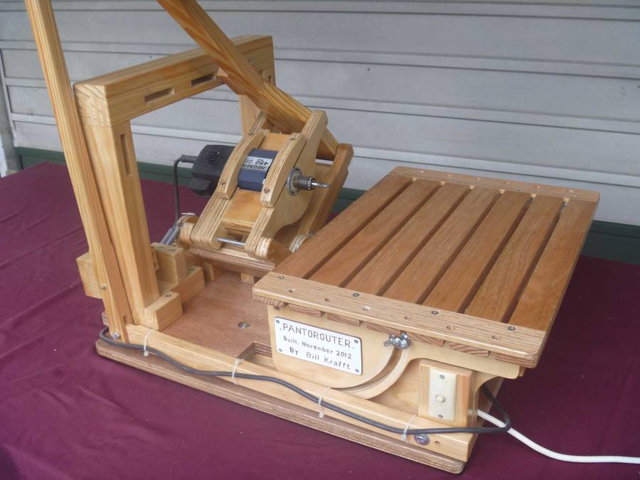
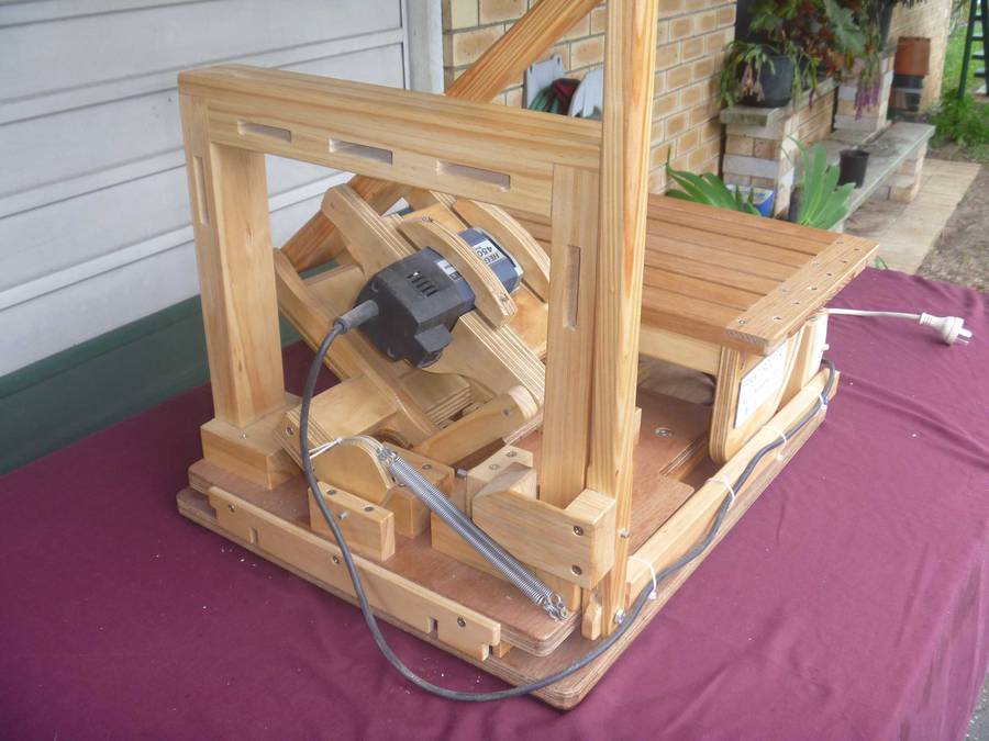
Bill Kraft's Pantorouter with Tilt-up table
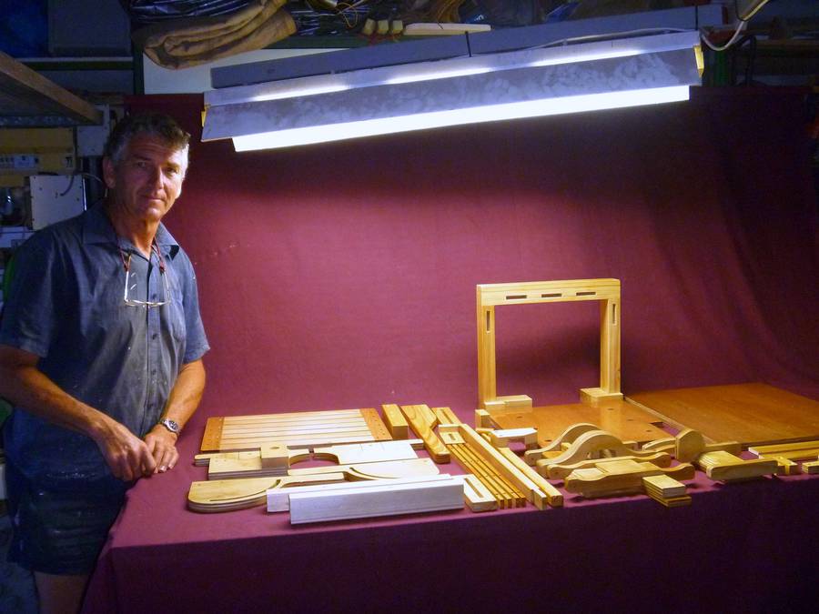
Bill Kraft, from Australia, writes:Hi Matthias,
I bought your pantorouter plans
in October last year and I would like to thank you for the detail
and completeness of the information. As you can see, I have built the machine with a couple
of changes to suit my use. I also made a couple of videos.
I live in Brisbane Australia and have purchased some more plans from you and I am looking
forward to building those machines as well.
 When I first started to think about building the Pantorouter,
I was going to build both a vertical and horizontal table, but then I
wondered if I could combine the two.
When I first started to think about building the Pantorouter,
I was going to build both a vertical and horizontal table, but then I
wondered if I could combine the two.
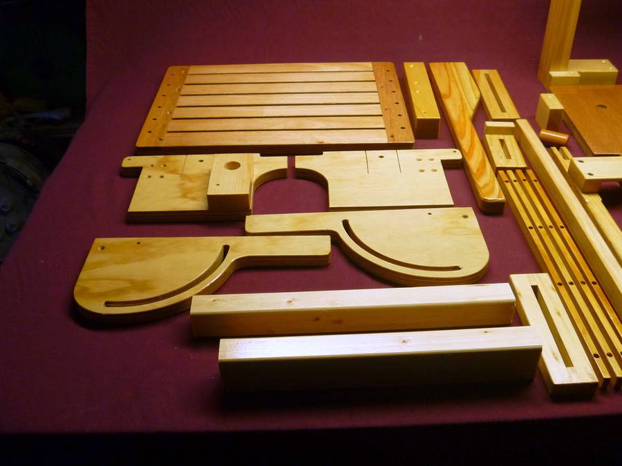
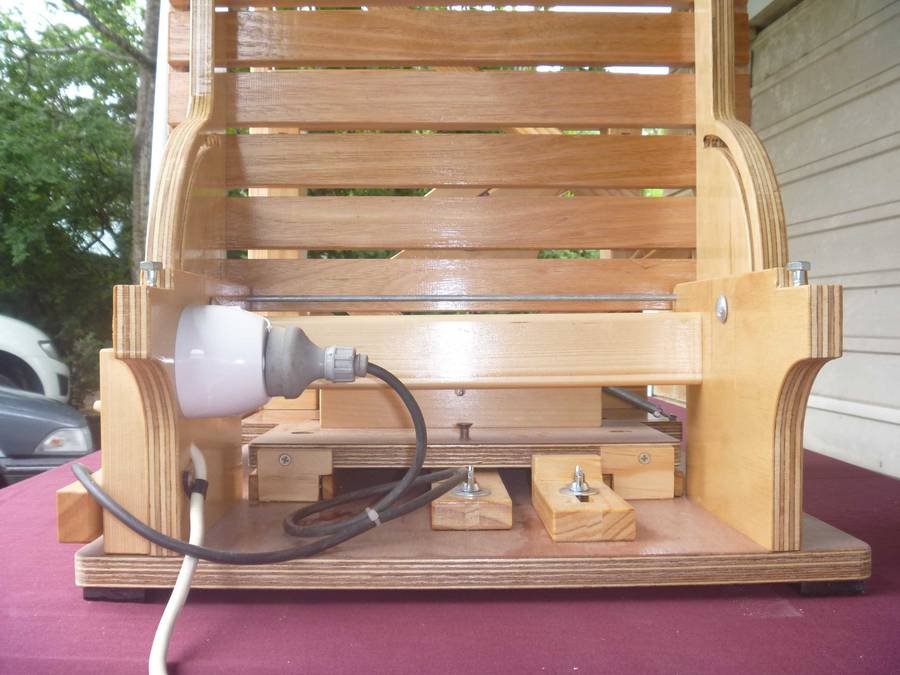
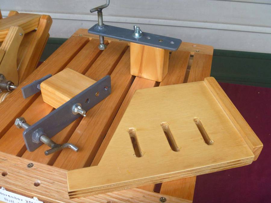
The table top is made up of 19mm thick hardwood slats. The front one is 45mm wide, so as to give some clearance underneath for the bolt up through the slot, clear of the front 35 mm x 35 mm cross member.
45mm x 8mm edge boards were installed so as to be able to screw down every second slat and also provide a bolt hole on the outside of the plywood chassis rail.
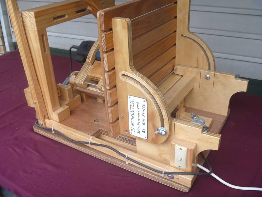
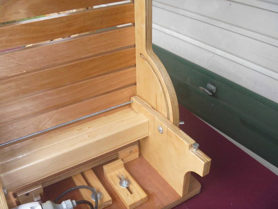
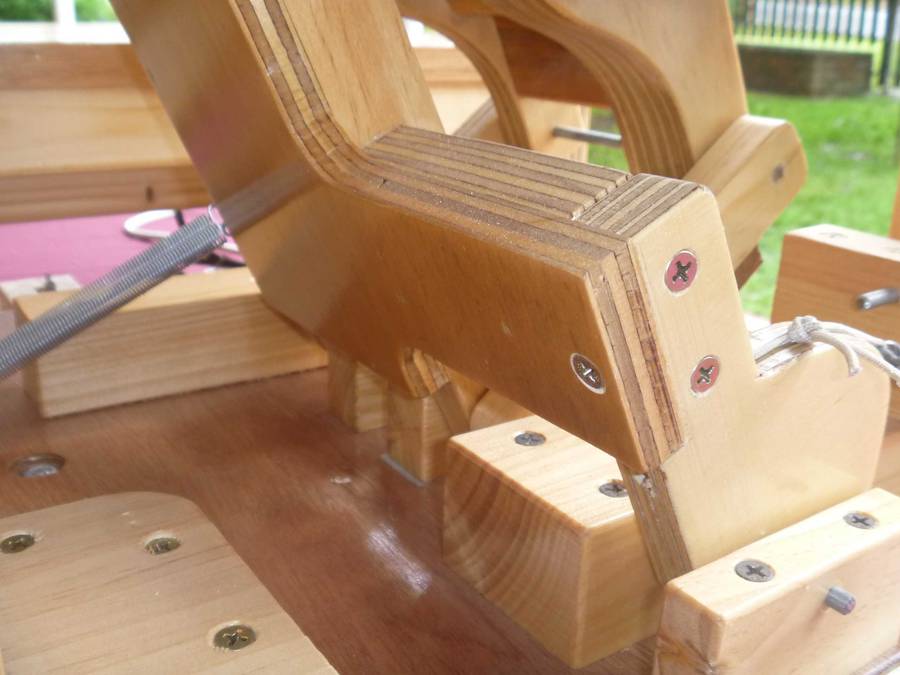
I installed a 1/4" coach screw to provide a vertical stop, however the vertical stop seemed more difficult. Instead, a drywall screw in the curved bolt slot seems to work very well.
 I have positioned the pivot point so that the bench top when pivoted is
35mm further away from the router. I did this so I could fit sacrificial
ply and holding jigs to the table top.
I have positioned the pivot point so that the bench top when pivoted is
35mm further away from the router. I did this so I could fit sacrificial
ply and holding jigs to the table top.
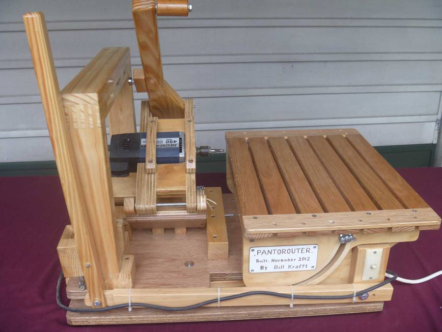
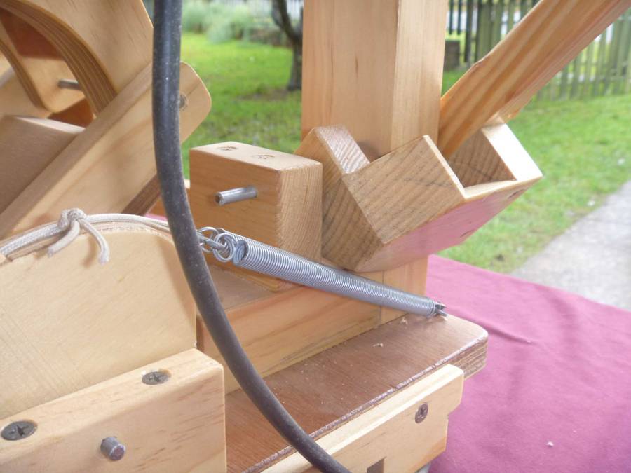
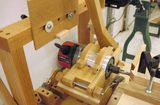
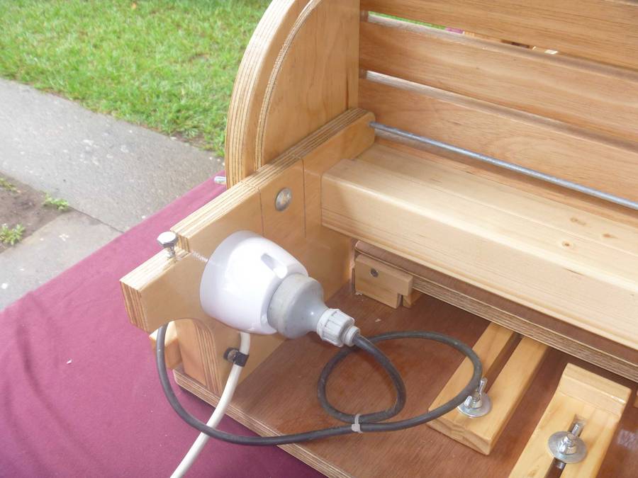 The switch block served an additional purpose as I extended the control
link through to mount onto this block also.
The switch block served an additional purpose as I extended the control
link through to mount onto this block also.
The longer control link became an excellent place to run the router power cable along to the remote switch. I installed a "ceiling fan" power socket under the table behind the switch, which allows the router to simply "plug in".
 The pivot rod is 5mm steel, same as the pantograph assembly.
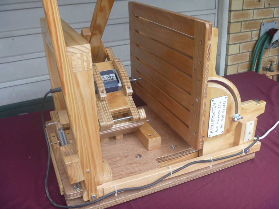
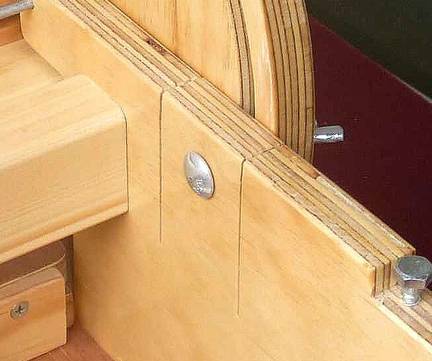
The base frame/chassis has two saw cuts to provide "relief" in the 18mm
plywood so that the "pinch bolt" can work effectively.
The 50mm x 35mm cross member on the base frame/chassis is located so the bottom of it is near level with the edge of the table top (when tilted).
I installed it there to allow better "clean out" of the shavings and wood dust.
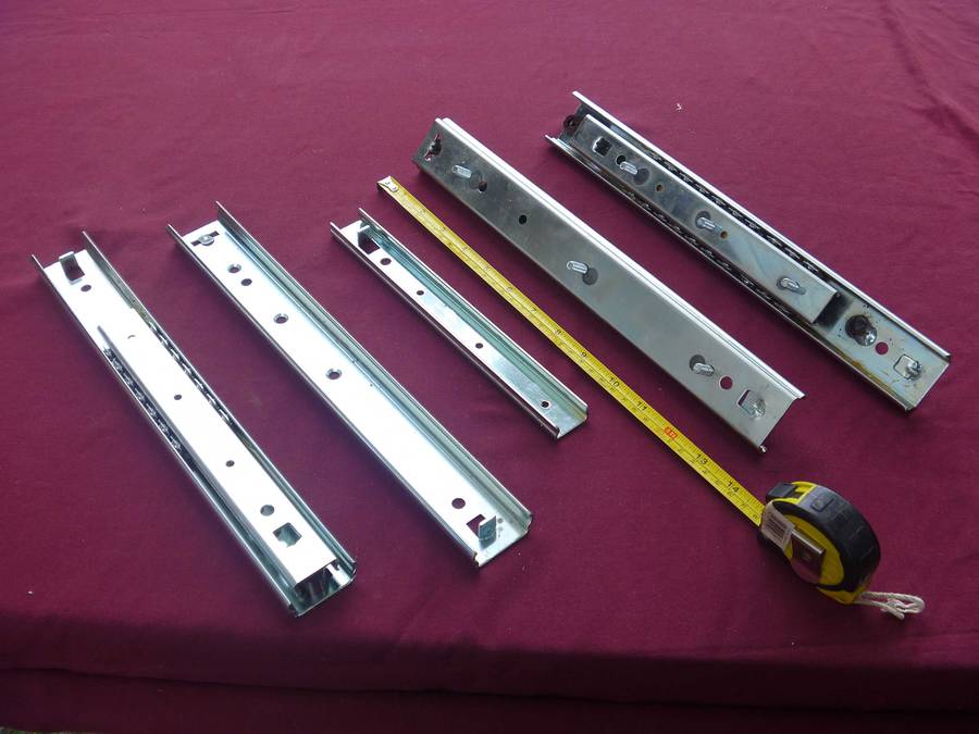
 The table was made higher than in the plans because the 60kg per pair drawer runners
were 21mm thick. To compensate for this, I also made the "dust
exclusion" rails 18mm high. Both slotted sled stops were also made 18mm
thick.
The table was made higher than in the plans because the 60kg per pair drawer runners
were 21mm thick. To compensate for this, I also made the "dust
exclusion" rails 18mm high. Both slotted sled stops were also made 18mm
thick.
I also made the "outward" sled stop longer as I was able to achieve 105mm sled travel, and I wanted to get the router out to its limit of the tracks.
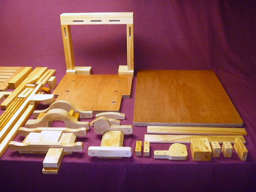
 I made the sled control arm pivot block from 35mm thick timber as the
25mm block seemed to limit the sled travel.
I made the sled control arm pivot block from 35mm thick timber as the
25mm block seemed to limit the sled travel.
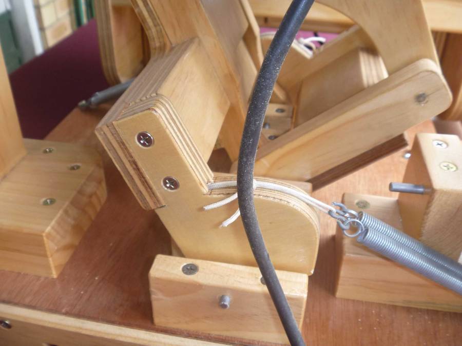 You will also notice that I extended the 11mm plywood out under the
spring connection arm on the long link.
You will also notice that I extended the 11mm plywood out under the
spring connection arm on the long link.
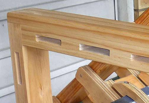
 When I made the template holder arch, I started with 130mm wide boards and cut 1/2 depth
slots at the mortise positions. Then I ripped the boards down the
middle and glued them together, face to face. The reason I did this is
that it was easy, and I am useless at cutting mortises by hand.
When I made the template holder arch, I started with 130mm wide boards and cut 1/2 depth
slots at the mortise positions. Then I ripped the boards down the
middle and glued them together, face to face. The reason I did this is
that it was easy, and I am useless at cutting mortises by hand.
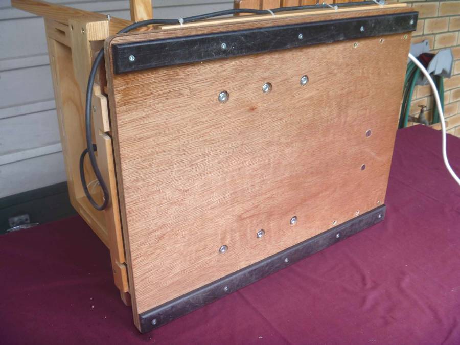 I have also fitted 12mm thick hard plastic runner rails under the marine
plywood base to try to limit the damage to the underside of the machine as
it gets moved from place to place.
I have also fitted 12mm thick hard plastic runner rails under the marine
plywood base to try to limit the damage to the underside of the machine as
it gets moved from place to place.
 I am very pleased with the outcome. It allows me to position the timber
on the bench while in the horizontal position, which is much safer and
allows much better access. Then I tilt the bench up to the vertical
position, complete the task, and then drop the table down to the
horizontal position again to remove the finished item. Too easy.
I am very pleased with the outcome. It allows me to position the timber
on the bench while in the horizontal position, which is much safer and
allows much better access. Then I tilt the bench up to the vertical
position, complete the task, and then drop the table down to the
horizontal position again to remove the finished item. Too easy.
See also:
 More reader built
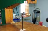 Reader built bandsaws
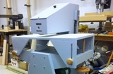 More reader projects
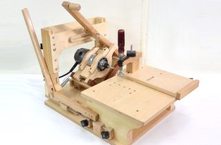 My pantorouter machine
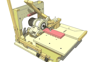 Pantorouter plans
Back to my woodworking website