Building the router mount
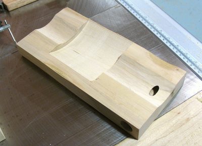 To mount the router, I cut a cove in a piece of maple to match
the 3.5" diameter of the cylindrical router body.
I also made a wider cutout in the back to allow for the larger back end
of the router.
To mount the router, I cut a cove in a piece of maple to match
the 3.5" diameter of the cylindrical router body.
I also made a wider cutout in the back to allow for the larger back end
of the router.
 I cut the cove for the router on the table saw using
this technique. I used my
cove table calculator to work out the
angle I needed to set the fence at to get the closest match to my router body.
I started by tracing the arc of the router body against the end of the piece of
wood, and then looked up the width and depth of the arc on a cove table for
a 7 1/4" blade. It worked out nicely, the cove fit perfectly on the
first try. For my 3 1/2" diameter router, and a 7 1/4" sawblade, the fence
angle was 40 degrees from the normal direction of cut.
I cut the cove for the router on the table saw using
this technique. I used my
cove table calculator to work out the
angle I needed to set the fence at to get the closest match to my router body.
I started by tracing the arc of the router body against the end of the piece of
wood, and then looked up the width and depth of the arc on a cove table for
a 7 1/4" blade. It worked out nicely, the cove fit perfectly on the
first try. For my 3 1/2" diameter router, and a 7 1/4" sawblade, the fence
angle was 40 degrees from the normal direction of cut.
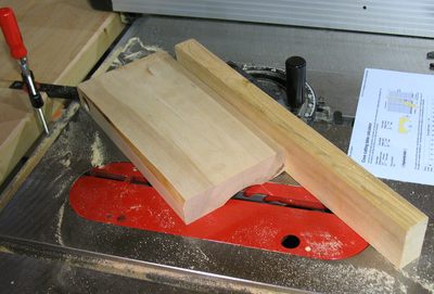
 I cut the larger cover for the back end of the router by passing
the workpiece 90 degrees on a 7.25" skillsaw blade. I just kept moving it back and
forth, each time raising the bade by another millimeter. In the photo at left, I have my
left hand on the saw's depth adjustment crank, and am using my right hand to move the
piece back and forth. I'm using the miter gauge as the back fence. It's fixed in place
by the featherboard hold down that I clamped into the slot behind it.
To limit motion of the block on the right side, I'm using the rip fence, and on the
left side, I'm using a small C-clamp on my miter gauge fence.
I cut the larger cover for the back end of the router by passing
the workpiece 90 degrees on a 7.25" skillsaw blade. I just kept moving it back and
forth, each time raising the bade by another millimeter. In the photo at left, I have my
left hand on the saw's depth adjustment crank, and am using my right hand to move the
piece back and forth. I'm using the miter gauge as the back fence. It's fixed in place
by the featherboard hold down that I clamped into the slot behind it.
To limit motion of the block on the right side, I'm using the rip fence, and on the
left side, I'm using a small C-clamp on my miter gauge fence.
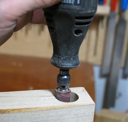
 To mount the bronze bushings, I drilled some 7/8" holes into the mounting block
with a forstner bit. The bushings went into those holes quite tightly, so I used a
drum sanding attachment on my Dremel tool to sand the insides of the holes out a little
bit to loosen the fit.
To mount the bronze bushings, I drilled some 7/8" holes into the mounting block
with a forstner bit. The bushings went into those holes quite tightly, so I used a
drum sanding attachment on my Dremel tool to sand the insides of the holes out a little
bit to loosen the fit.
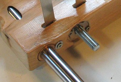
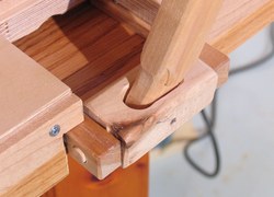
The shot at left shows the bottom edge of the mounting bracket. I added a small screw
and washer to the edge of the bushing to make sure the bushing didn't work itself
out of the piece of wood eventually.
To the right of that is a T-nut, which is there to engage the threaded rod for raising
and lowering the router mount. I mounted it flush with the surface in a shallow 1" hole.
The T-nut is also locked down by two #6 countersink screws.
You can also see the 5/8" steel shaft through an oval opening in the top left of the
photo. My cove ended up cutting into the oversized hole I drilled for the 5/8" shaft.
I cut into the hole with my cove cut, but rod itself is just barely
positioned such that it doesn't protrude into the cove.
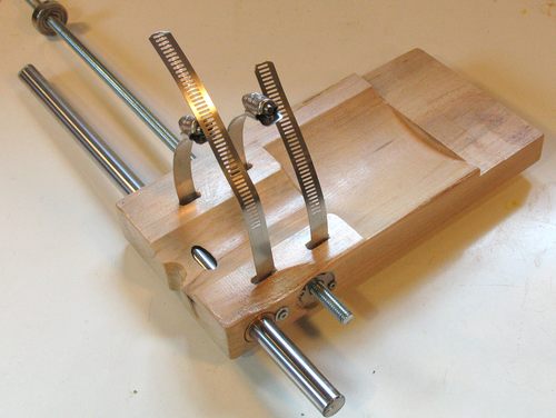 I just used a pair of hose clamps to hold the router in place. I wasn't sure if this
would work well enough when I tried it, but it worked out well. My original idea was
to build some sort of solid mounting bracket for the router. The hose clamps turned
out to be the better solution, as it left enough space next to the router
for a 3" dust hose.
I just used a pair of hose clamps to hold the router in place. I wasn't sure if this
would work well enough when I tried it, but it worked out well. My original idea was
to build some sort of solid mounting bracket for the router. The hose clamps turned
out to be the better solution, as it left enough space next to the router
for a 3" dust hose.
This way of mounting the router has worked out very well, and I ended up using
the combination of a cove cut and hose clamps again for my home made wooden
router lift.
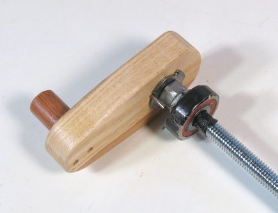 This is the crank for raising and lowering the router. I wrapped some electrical tape around
the threaded rod to get the bearing on nice and tight. I also wrapped some tape around
the edge of my bearing. I was out of 3/8" inner diameter ball bearings, so I ended up using
a metric size ball bearing, with a 10 mm inner diameter, 30 mm on the outside.
But my drills are in fractional inches.
So the tape brings it up to size to fit snugly in a slightly larger fractional inch sized
hole.
This is the crank for raising and lowering the router. I wrapped some electrical tape around
the threaded rod to get the bearing on nice and tight. I also wrapped some tape around
the edge of my bearing. I was out of 3/8" inner diameter ball bearings, so I ended up using
a metric size ball bearing, with a 10 mm inner diameter, 30 mm on the outside.
But my drills are in fractional inches.
So the tape brings it up to size to fit snugly in a slightly larger fractional inch sized
hole.
I was originally going to put nuts on both sides of the ball bearing. But I found that
whenever I locked the bearing between two nuts, it would go on at a slight angle. So
the nuts probably don't sit on the shaft perfectly either. With it just pressed against
a nut on the top, and jammed on with the electrical tape, I got it nice and co-axial
with the threaded rod.
With only a nut on the top side of the bearing, I can't use the crank to push
the router down. But the bronze bushings slide freely enough on the shaft that
gravity is more than enough to pull the router down as I lower it.
The weight of the router is also enough to hold it in place while cutting reasonably
sized mortises. For larger mortises, I should probably tighten the vertical lock knob to fix it in place.
Making the vertical frame
 I only used spruce for most of the frame to hold the router, though I made sure
it was some of the heaviest and hardest spruce I had around (I even
tested it for hardness)
I only used spruce for most of the frame to hold the router, though I made sure
it was some of the heaviest and hardest spruce I had around (I even
tested it for hardness)
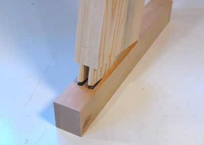
I went a bit overboard and used a double tenon joint to mount the spruce frame
onto the maple rails that screw onto the base.
For the joints at the top of the frame, I joined it with a very tight box joint,
with fingers just 1/4" wide, made with my
screw advance box joint jig
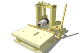
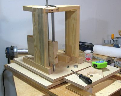 This picture shows the frame built, and starting to figure out how to mount
the router mounting bracket.
This picture shows the frame built, and starting to figure out how to mount
the router mounting bracket.
This project is one of those projects that I didn't design ahead of time. I really
wasn't sure what would work and what wouldn't work, so I just made parts and
experimented as I went along. I do fairly well that way. I'm proud to say that there
isn't a part on the machine that I had to make twice or throw away. Though
I did modify and add a lot of parts. If I had to build another machine like that,
there are only a few things that I would do differently.
 To help guide the router, I needed another vertical rail in the back, parallel to the vertical
edges of the frame. To mount this, I had to add an extension to the back of the frame.
While I was at it, going nuts with tight joints and double tenon joints, I decided to mount
this extension with a double tenon joint as well. The double tenon joint
doesn't go all the way to the corner, because I didn't want to weaken the corner
box joint by cutting a mortise into it.
To help guide the router, I needed another vertical rail in the back, parallel to the vertical
edges of the frame. To mount this, I had to add an extension to the back of the frame.
While I was at it, going nuts with tight joints and double tenon joints, I decided to mount
this extension with a double tenon joint as well. The double tenon joint
doesn't go all the way to the corner, because I didn't want to weaken the corner
box joint by cutting a mortise into it.
If I hadn't already had a mortising machine
when I build this one, I might not have used quite so many mortise and tenon
joints to build this machine.
Actuating lever
 To move the router side to side and front to back, I made a mechanism with just one lever.
The base of the lever can tilt in a block, and this block can tilt side to side.
To move the router side to side and front to back, I made a mechanism with just one lever.
The base of the lever can tilt in a block, and this block can tilt side to side.
 The lever is attached to another bracket about one third of the way up along the lever.
This bracket tilts up and down, as the lever's attachment point moves up and down
a bit as the lever goes through its full range of motion. The lever is screwed against a block
on the bracket. This block also tilts, which also allows for two degrees of freedom.
The lever is attached to another bracket about one third of the way up along the lever.
This bracket tilts up and down, as the lever's attachment point moves up and down
a bit as the lever goes through its full range of motion. The lever is screwed against a block
on the bracket. This block also tilts, which also allows for two degrees of freedom.
On commercial slot mortising machines, both mounting points of the lever would typically
be ball joints of some sort, but a ball joint is not something easily made out of wood.
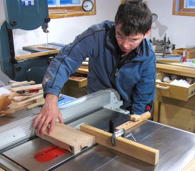
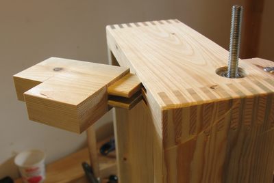
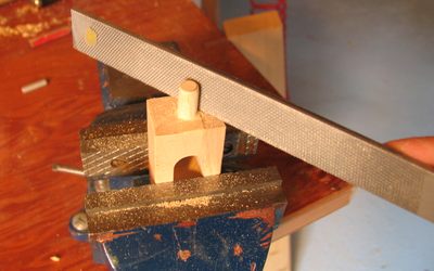 This photo shows making the block that the base of the lever sits in. The block has two
round ends that fit into round holes in the blocks that it mounts to. The round ends are
actually integral parts of the lever (round tenons, essentially). I cut these out square on
the band saw, and filed them round with a file.
This photo shows making the block that the base of the lever sits in. The block has two
round ends that fit into round holes in the blocks that it mounts to. The round ends are
actually integral parts of the lever (round tenons, essentially). I cut these out square on
the band saw, and filed them round with a file.
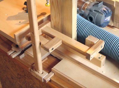
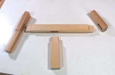 The photo at left shows the parts of the bracket in the earlier photo. The bracket is all
done with mortise and tenon joints. I cut these on my old mortising machine, though,
realistically, I could have already cut these on the new machine just by moving
the router carriage with my hands directly instead of using the lever.
The photo at left shows the parts of the bracket in the earlier photo. The bracket is all
done with mortise and tenon joints. I cut these on my old mortising machine, though,
realistically, I could have already cut these on the new machine just by moving
the router carriage with my hands directly instead of using the lever.