I previously covered how DC motors work, but AC
induction motors are actually much more useful for homemade machines
such as bandsaws.
Induction motors are more difficult to understand. It was the wicked and
insane genius Nikola Tesla who invented them. There is an
extensive Wikipedia
article on induction motors, so I'll try to keep this page simple.
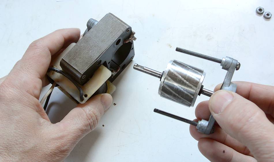
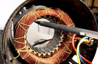
Here I just pulled the rotor out of a small shaded pole induction motor
(the type that would be used to power the fan inside the freezer part of
a fridge). There are no electrical connections to the rotor.
The rotor is also not a magnet, though it is attracted by a magnet.
Note the slanted lines on the rotor. These are actually a sort
of short-circuit winding, made of aluminium, which has been cast in
place (the light coloured disks at either end form part of this short
circuit winding). This short circuit winding is key to what makes the
motor work.
If the rotor is subjected to a changing magnetic field, a small voltage
is induced in the windings. Because the windings are a short circuit,
this causes a current to flow, which in turn creates a magnetic field
that opposes the change in magnetic field. The windings effectively
make for a rotor that, though magnetically permeable, resists rapid
changes to its magnetic field.
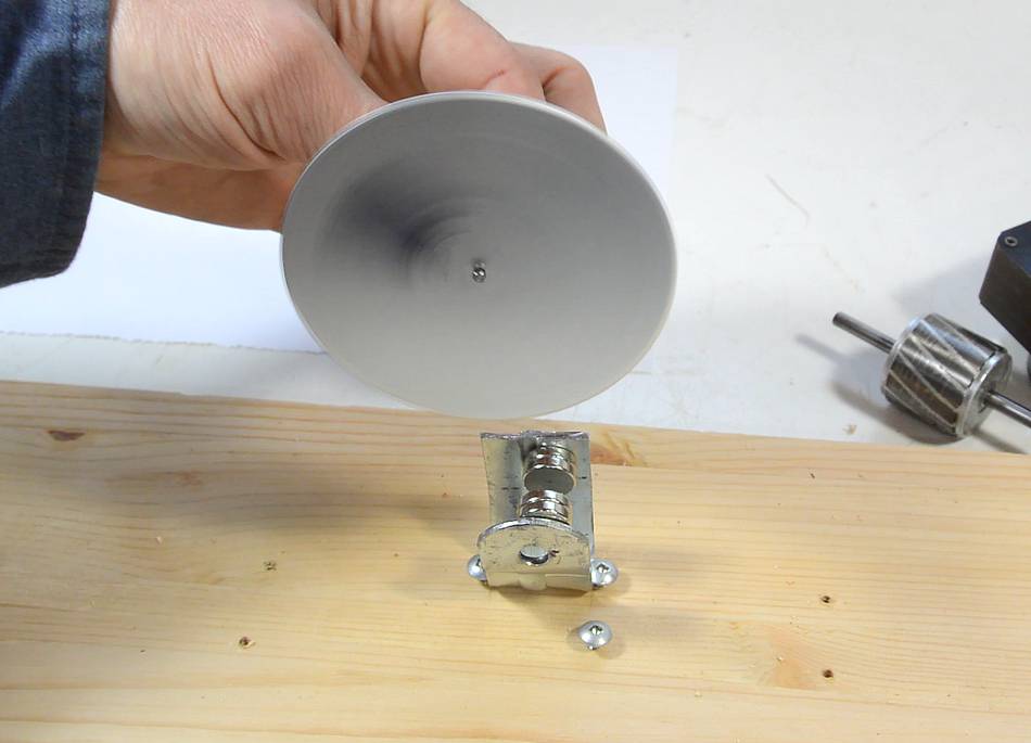
A similar effect can be demonstrated by spinning an aluminium disk, and
subjecting part of it to a magnetic field through the disk. As the
spinning disk is held between the magnets attached to the metal bracket
in this photo, it slows right down. Like in an induction motor rotor,
the changing magnetic field induces a current flow in the aluminium,
which in turn counteracts the change. The magnetic field through the
disk trails behind the rotation, pulling it back, and stopping the
rotation in short order (in fact, within a quarter turn of the disk).
I recommend watching the video at the top of this article, it makes this
much more clear.
The fact that the rotor doesn't like changes in magnetic field makes an
induction motor work as an electric brake when DC is applied to
its windings.
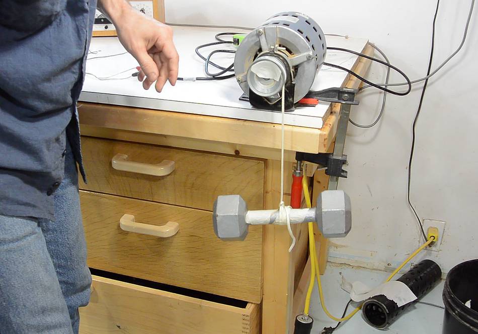
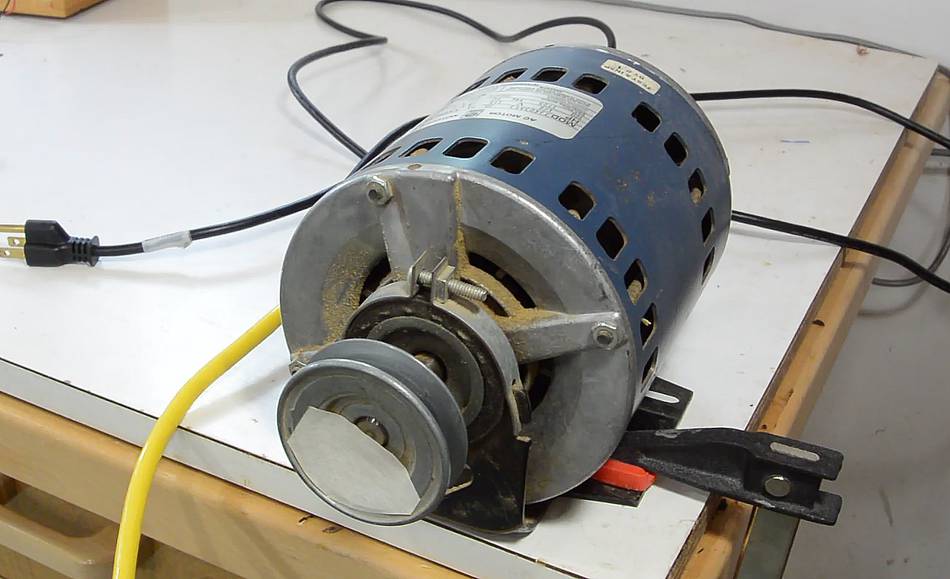
Here I have a 10-pound weight attached to a pulley on the motor.
Applying a few amperes to the windings of this half horsepower furnace
motor is enough to cause the weight to drop very slowly. However, no
matter how much current is applied, the weight will still drop slowly,
because the rotor only resists a change in magnetic field, so
the breaking effect only happens when the rotor turns.
So far, we have established that induction motors are good at not
turning. But if the magnetic field moves, the rotor wants to turn with it.
Going back to the example with the metal disk, if I move the magnets
quickly past the disk, the disk starts spinning to follow the magnets.
If we spun the stator around the rotor, that would get the rotor spinning
as well. But that would be useless as a motor.
In a three-phase AC induction motor, we create a spinning magnetic field
by applying electrical current to different windings at different times.
Imagine current passed through the blue windings, so that pole 1 is
North and pole 4 is South. Next, we pass current through the red
windings so that 2 is North and 5 is South, then through green,
making 3 North, and then again through blue, but in the opposite
direction as before, so that 4 is North and 1 is south. This will
create a rotating magnetic field.
In a real three-phase motor, we actually apply sine waves to all three
windings simultaneously. The sine waves are all 60 degrees (or one
sixth of a cycle) out of phase from each other so that North smoothly
transitions from 1 to 2, 2 to 3, etc.
The stator creates a rotating magnetic field. The rotor
will become passively magnetized by this field. But the rotor's
short-circuit windings cause it to resist changes in magnetic field,
so the rotation of the field in the stator will lag behind that in
the rotor. With the angle of the field in the stator lagging behind,
magnetic attraction will cause the rotor itself to turn, eventually
at a speed close to, but not quite that of the rotating field
in the stator.
I should add that in an actual three-phase transmission, the phases are
120° (one third of a cycle period) out of phase from each other, not 60°.
But we can get 60° by taking the third phase, which is 240° degrees
out of phase from the first and swapping the wires, which reverses it, or changes
it's phase by 180°. 240 - 180 = 60. The phases are 120° degrees
out of phase with each other so that the sum of the currents through all
three phases always adds up to zero. That way, no current needs to flow
through neutral (ground) conductor.
The operation of three-phase induction motors is easier to understand,
but most houses only have single-phase AC. However, in North American
120 volt systems, single-phase power is often referred to as two-phase
power, because there are two opposite phases of 120 volts. But these
are 180 degrees out of phase. This makes for 240 volts between them,
but doesn't get us any closer to a rotating field.
With single-phase, we can only make a field that goes back and forth.
However, if we subject an induction motor rotor to a back and forth
field, and it is already spinning, it will follow the back and forth,
much like you can keep a flywheel and crank spinning by just pushing and
pulling on a crank. But the alternating field won't be enough
to get the motor spinning from a standing start.
In single-phase motors, getting the motor spinning usually involves some
starting winding, which, though it doesn't exactly make a rotating
field, at least makes an alternating field that has some rotational
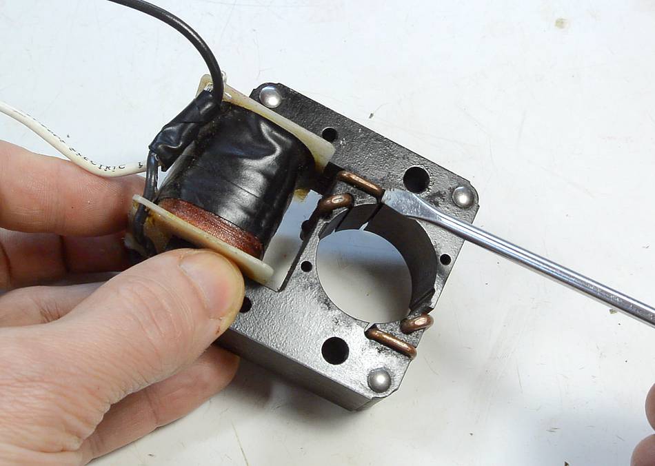
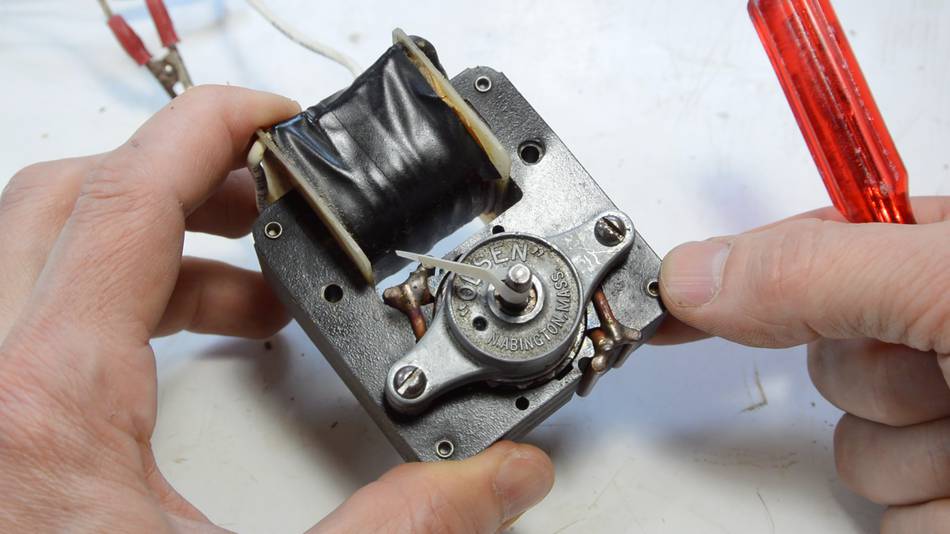
component to get the rotor started. For example in a shaded pole
motor, we have some copper short-circuit winding on one side of each
pole. The short-circuit winding resists changes in magnetic field,
causing the change in magnetic field through the short-circuit winding
to always lag behind that in the main pole.
This causes the rotor to be compelled to turn from the main pole towards
the short circuited part as the magnetic field changes, because the
shaded part will lag behind the main pole. With the rotor resisting
changes in field as well, the field in the rotor, though aligned with
the main pole, is behind, so it's attracted to the shaded part of the
pole.
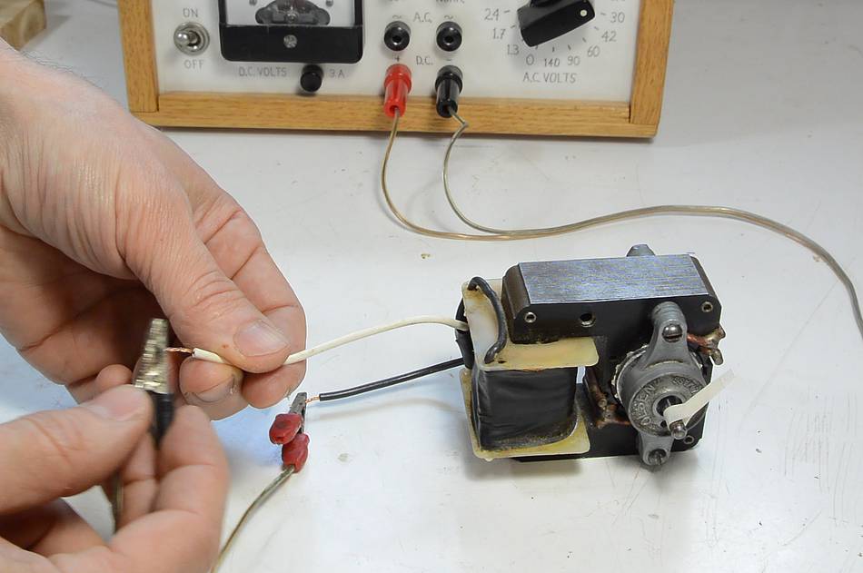
This effect even works if just DC pulses are sent into the motor.
Provided that the motor rotates easily, each pulse will cause the rotor
to turn by a few degrees.
When AC is applied, the motor runs continuously.
But the shaded poles don't provide very much starting torque. In fact,
the torque produced by a stalled shaded pole motor is considerably
less than when it's running near full speed. But it's enough to get
the motor running.
But shaded poles are short circuit windings, so they consume
a lot of power. This makes shaded pole motors very inefficient.
In larger single-phase motors, 1/4 horsepower and up, starting is
usually accomplished by an auxiliary winding. The auxiliary winding is either
one with fewer turns and more resistance, or in series with a capacitor.
Either method makes for a magnetic field slightly out of phase with
the main field, thus adding a rotational component to the field, which is
enough to get the motor started.
But the starter winding is usually inefficient, so most
single-phase motors have a centrifugal switch which disconnects the
starter winding once the motor is up to speed. This switch closing
(reconnecting) again is what causes the "click" you hear from a lot of
motors as they wind down, a second or two after having been turned off.
There are numerous ways that the starter winding on single-phase motors
can work. These include:
Capacitor start motors
Resistive start motors
Split phase motor (Also known as capacitor run motors)
I could write a lot more on starting methods for single-phase motors, but
it's quite an involved topic, so I won't go into details here. However
the Wikipedia article
on induction motors has a lot more detail.
Two pole and four pole
Most induction motors are either two-pole or four pole. In a two-pole motor,
the stator has one north and one south pole at any time, and the rotor needs
to turn one full rotation (or close to that) for each cycle. For 60 Hz systems,
a two pole induction rotor will run anywhere from 3500 to 3600 RPM (or about 58-60
turns per second). For 50 Hz systems, a two-pole motor will run 2900 to 3000 RPM.
In a four-pole motor, the stator at any time has two north and two south poles,
with north and south always 90 degrees apart (thus, two north and two south poles
are always opposite each other). The rotor becomes magnetized to this pattern.
Only half a rotation is needed per cycle, and a four pole motor will run
at 1725 to 1800 RPM for 60 Hz systems, and 1425 to 1500 RPM for 50 Hz systems.
Motors with more than four poles are much less common and only used for
special applications. A typical "box fan" motor will have six poles,
and a ceiling fan motor will have eight or more poles.
Varying speeds
A main disadvantage of induction motors is that they are not practical for
variable speed operation. With the field spinning at a fixed speed (determined by
the AC current supply), the motor only runs efficiently when it's running close
to that speed. For small household fans, lower speed operation is
achieved by allowing a large amount of "slip", that is, the rotor may
rotate as slow as half the speed of
the field, but this makes for a very inefficient motor, and the speed of rotation
is highly dependent on the load, so this approach is not suitable
for driving machinery.
However, electronic variable frequency drives (VFD)
are sometimes used with induction motors. A VFD re-synthesizes
AC at different frequencies and feeds that into the motor so that the motor
itself is still running at close to the speed of the magnetic field.
Many newer (after 2000) lathes with electronically variable speeds use
variable frequency drives.
 Here I just pulled the rotor out of a small shaded pole induction motor
(the type that would be used to power the fan inside the freezer part of
a fridge). There are no electrical connections to the rotor.
The rotor is also not a magnet, though it is attracted by a magnet.
Here I just pulled the rotor out of a small shaded pole induction motor
(the type that would be used to power the fan inside the freezer part of
a fridge). There are no electrical connections to the rotor.
The rotor is also not a magnet, though it is attracted by a magnet.


 Reversing single phase induction motors
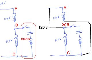 Rewiring a motor from 240 and 120 volts
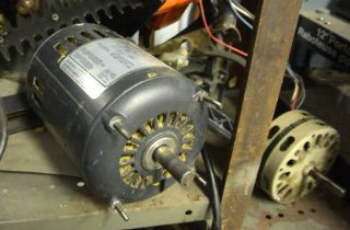 Where do you get your motors from?
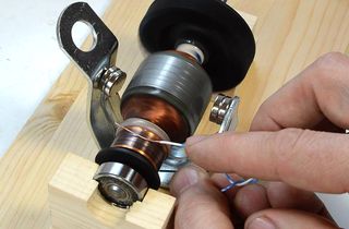 How DC motors work
 Induction motor vs. universal motor on my jointer, comparison
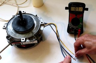 Figuring out a mystery motor
 Wiring up and reusing a clothes dryer motor
 Washer motor wiring for reuse in projects
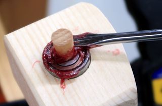 Re-greasing shielded bearings, no disassembly
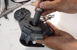
 Fixing seized oscillating fan motor
 Building a dust collector blower
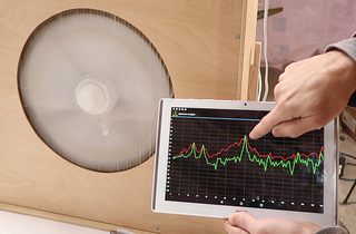 Measuring RPM with a spectrum analyzer app
 Gyro effect explained
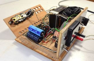 Homemade benchtop power supply
 How crowned pulleys keep a flat belt tracking
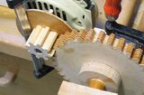 Motorizing the apple grinder
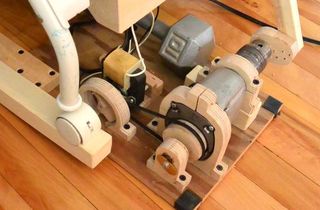 Baby rocking machine
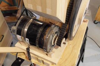 Motorizing the bandsaw
 Making a simple remote switch
 Installing a 240 volt circuit
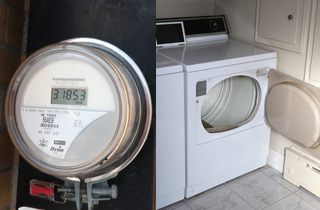 Using a utility electricity meter to measure appliance power usage