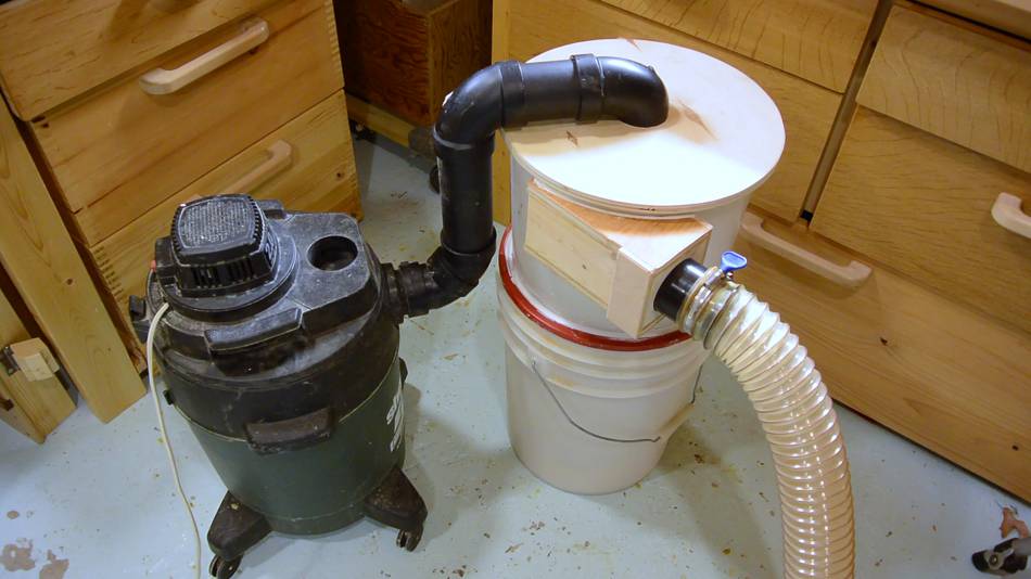
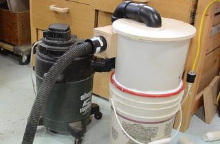
 Having built my two bucket cyclone, I figured
I might as well build a dust collector to use with it instead of that
noisy ShopVac. The trickiest part of building a dust collector
is the blower.
Having built my two bucket cyclone, I figured
I might as well build a dust collector to use with it instead of that
noisy ShopVac. The trickiest part of building a dust collector
is the blower.
Having built my two bucket cyclone, I figured
I might as well build a dust collector to use with it instead of that
noisy ShopVac. The trickiest part of building a dust collector
is the blower.
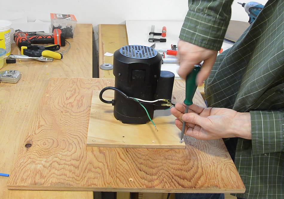
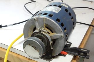
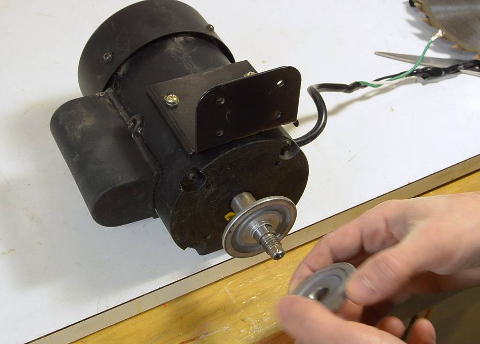 For my previous dust collector, I used a 1/3 hp
motor from a tile saw. That motor was barely adequate, so this time, I
used a 2/3 hp motor from a really cheap "JobMate" table saw I
bought for $20, just for the motor.
For my previous dust collector, I used a 1/3 hp
motor from a tile saw. That motor was barely adequate, so this time, I
used a 2/3 hp motor from a really cheap "JobMate" table saw I
bought for $20, just for the motor.
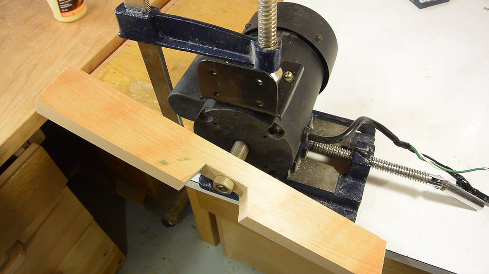 From my previous experiments I
knew that a paddle spinning in free air took about as much power to spin
as an impeller with the same dimensions.
So I experimented with how long a board I could spin with this motor
without overloading it.
From my previous experiments I
knew that a paddle spinning in free air took about as much power to spin
as an impeller with the same dimensions.
So I experimented with how long a board I could spin with this motor
without overloading it.
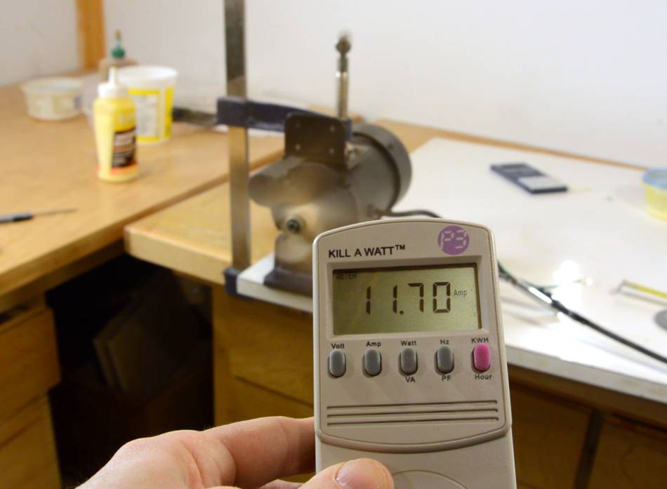
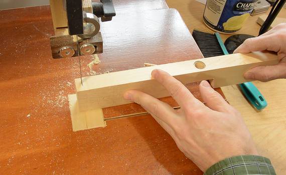 I started with a longer board, but the motor was overloaded. Then I
shortened it until the current reading became acceptable for a 2/3 hp motor.
I started with a longer board, but the motor was overloaded. Then I
shortened it until the current reading became acceptable for a 2/3 hp motor.
After shortening it enough, I narrowed the board a bit and found I was able to add length to it again, this time by attaching two pieces of duct tape at the ends.
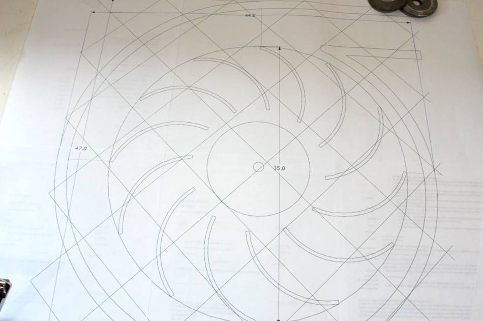 I was able to spin a board as long as 34 cm. I then designed an
impeller and housing using SketchUp.
I designed the impeller at 35 cm,
figuring if it overloaded the motor, I could always cut it down a
little bit.
I was able to spin a board as long as 34 cm. I then designed an
impeller and housing using SketchUp.
I designed the impeller at 35 cm,
figuring if it overloaded the motor, I could always cut it down a
little bit.
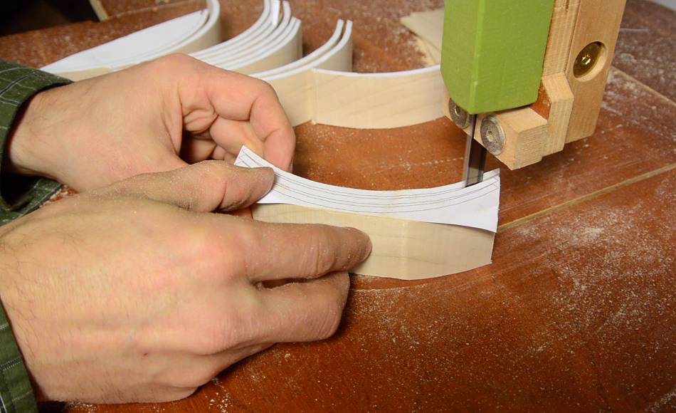
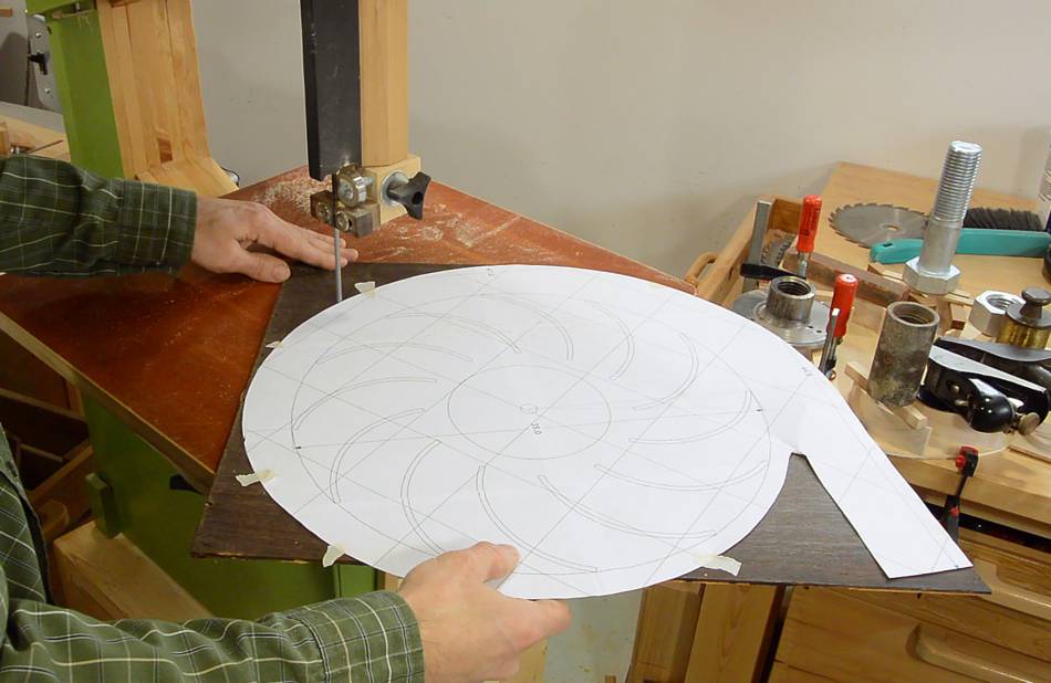
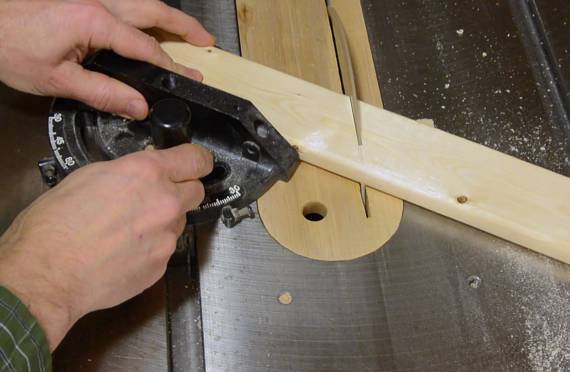
 I also printed out some cutting templates for cutting the curved vanes
of the impeller on my bandsaw. Cutting from the paper template
eliminated any inconsistencies I might have introduced by drawing the
arcs on the wood with a compass.
I also printed out some cutting templates for cutting the curved vanes
of the impeller on my bandsaw. Cutting from the paper template
eliminated any inconsistencies I might have introduced by drawing the
arcs on the wood with a compass.
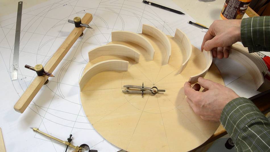
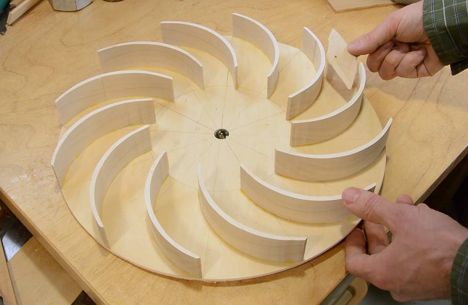
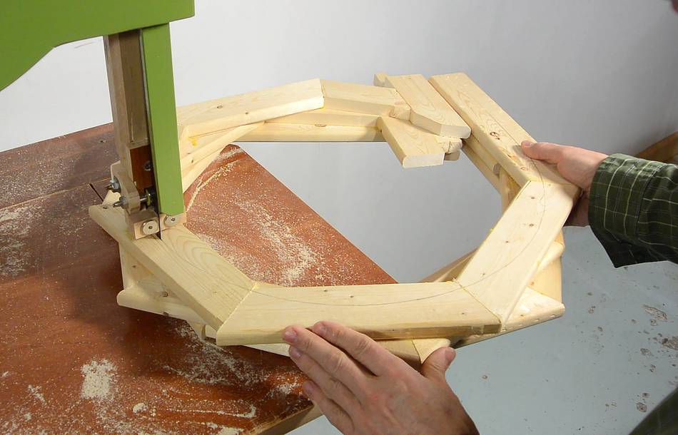
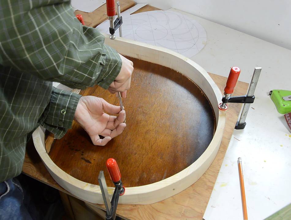
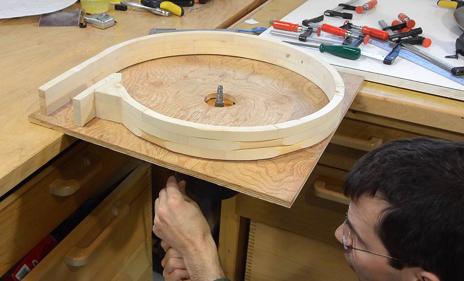
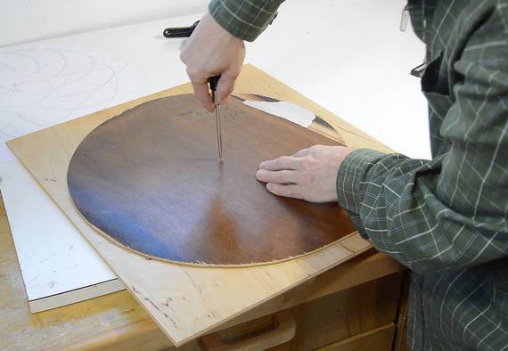
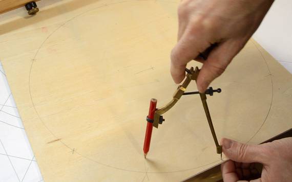 But to lay the vanes out on the wood, I re-created the geometry with
compasses on the plywood disk. This was easier than transferring
the marks from the template to the wood.
Here, I'm just checking the geometry
by placing a few of the vanes on the impeller disk.
But to lay the vanes out on the wood, I re-created the geometry with
compasses on the plywood disk. This was easier than transferring
the marks from the template to the wood.
Here, I'm just checking the geometry
by placing a few of the vanes on the impeller disk.
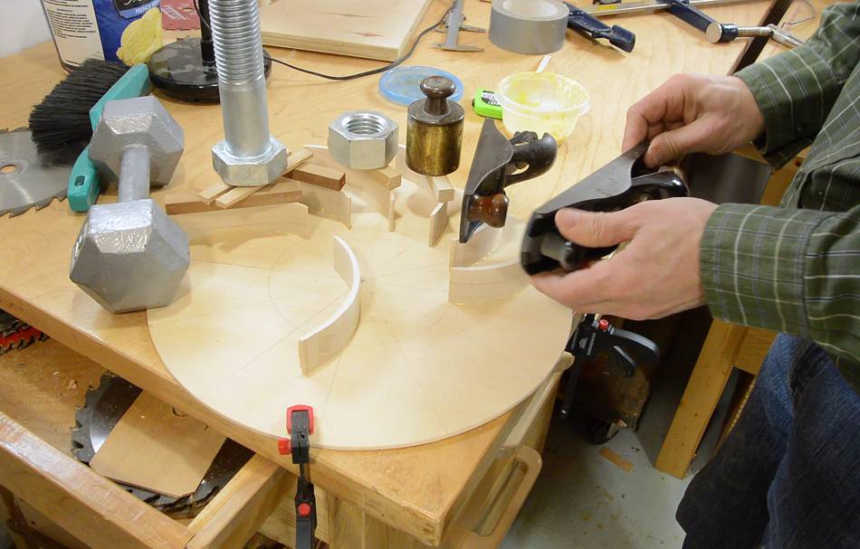
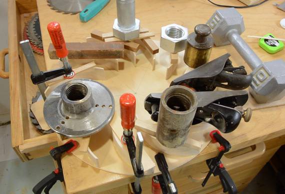 I used various heavy objects to weigh down the
vanes as I glued them. The plywood wasn't totally flat, so I wanted
it pressed against a flat table top while gluing, and clamps would
have been awkward for that.
I used various heavy objects to weigh down the
vanes as I glued them. The plywood wasn't totally flat, so I wanted
it pressed against a flat table top while gluing, and clamps would
have been awkward for that.
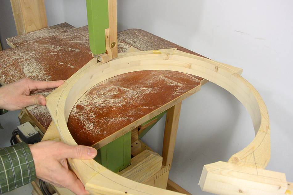
 I used some scrap plywood to cut out the shape of the inside of the
blower housing from the template.
I used some scrap plywood to cut out the shape of the inside of the
blower housing from the template.
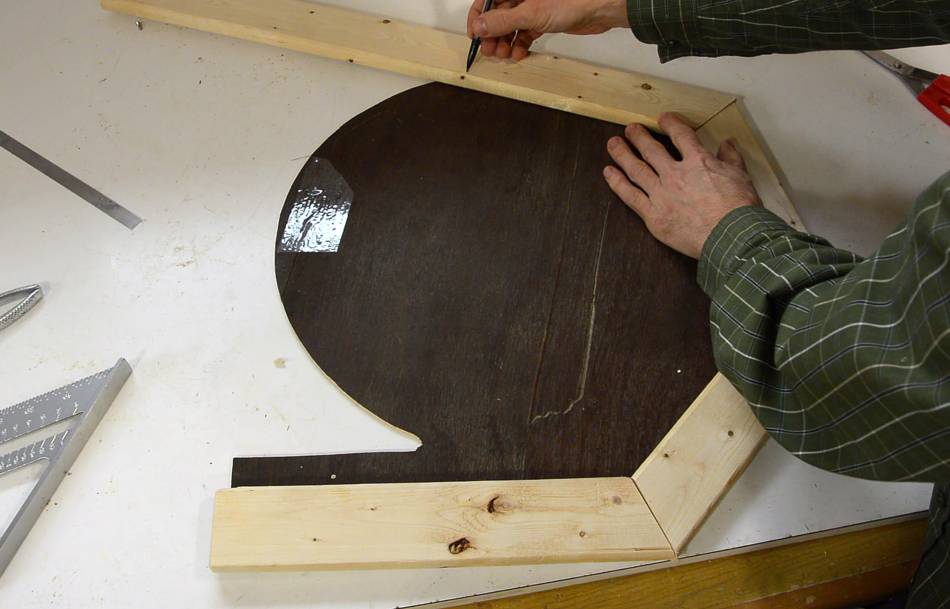
 I then used that plywood shape to lay out pieces for the housing.
I figured this time I'd build the housing up in alternating layers,
similar to what is often done in
segmented turning.
I just freehand marked what angles I needed, then cut the next piece's
angle to match.
I then used that plywood shape to lay out pieces for the housing.
I figured this time I'd build the housing up in alternating layers,
similar to what is often done in
segmented turning.
I just freehand marked what angles I needed, then cut the next piece's
angle to match.
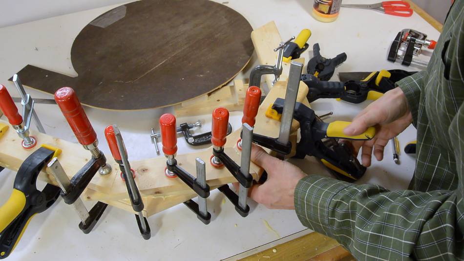 I gradually worked my way around the spiral housing. But it was difficult
to make sure I had wood where I needed it. The clamps got in the way of the
template, and I couldn't quite see how the lower layers lined up with the template.
I gradually worked my way around the spiral housing. But it was difficult
to make sure I had wood where I needed it. The clamps got in the way of the
template, and I couldn't quite see how the lower layers lined up with the template.
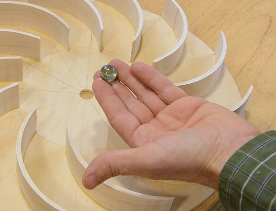 I kept alternating between working on the impeller and the housing as I waited
for various glue-ups to dry. The impeller glue had dried by this time,
so I could balance it.
I kept alternating between working on the impeller and the housing as I waited
for various glue-ups to dry. The impeller glue had dried by this time,
so I could balance it.
I balanced it by balancing it on a marble and seeing which way it had a tendency to tip. I made a small block of wood, which I glued between the vanes to fix the imbalance.
 But at this time, I realized I made a major screw-up. My motor, looking at the shaft,
turns counter clockwise. But the impeller, as mounted on the shaft,
needs to have the vanes curved away from rotation. So it absolutely needs to
turn clockwise. I opened up the motor, but it would have required major surgery on
the internal wiring to reverse it.
But at this time, I realized I made a major screw-up. My motor, looking at the shaft,
turns counter clockwise. But the impeller, as mounted on the shaft,
needs to have the vanes curved away from rotation. So it absolutely needs to
turn clockwise. I opened up the motor, but it would have required major surgery on
the internal wiring to reverse it.
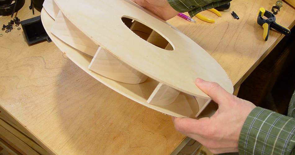
So I had another idea. I made what was the back plate of the impeller into the front, by cutting a big (12 cm diameter) hole in it, and glued a disk with just a shaft plate against the "front", which would now become the back. By flipping the impeller around, the orientation of the vanes was reversed.
I had to be really careful centring the new backer as I glued it on, or the impeller would have been thrown way off-balance. Luckily, after this change, the impeller only needed minor re-balancing.
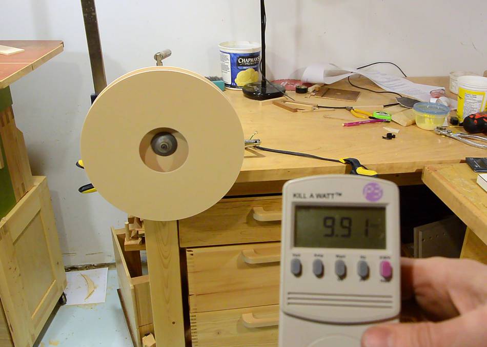
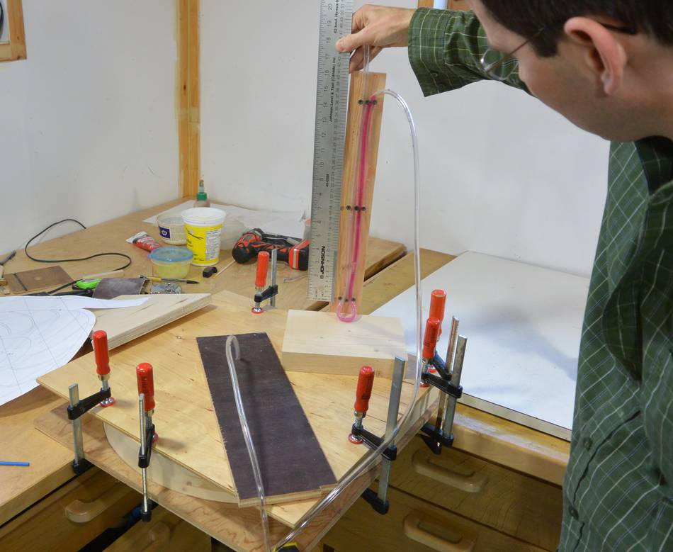
 With the glue dried, I mounted it on the motor. It had a slight
side-to-side wobble, but a paper shim on the arbour flange fixed that mostly.
The motor consumed about 10 amperes with it spinning in free air. From
my previous experiment, I knew that it would consume about the same
amount of power once mounted inside the housing.
With the glue dried, I mounted it on the motor. It had a slight
side-to-side wobble, but a paper shim on the arbour flange fixed that mostly.
The motor consumed about 10 amperes with it spinning in free air. From
my previous experiment, I knew that it would consume about the same
amount of power once mounted inside the housing.
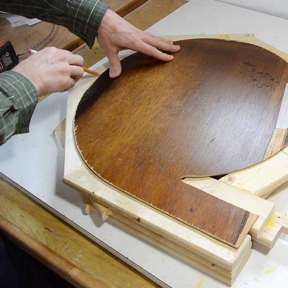 In the mean time, the glue for the housing had fully dried. I traced
the outline of the housing inside on the glue-up, then cut that out on
the bandsaw.
In the mean time, the glue for the housing had fully dried. I traced
the outline of the housing inside on the glue-up, then cut that out on
the bandsaw.
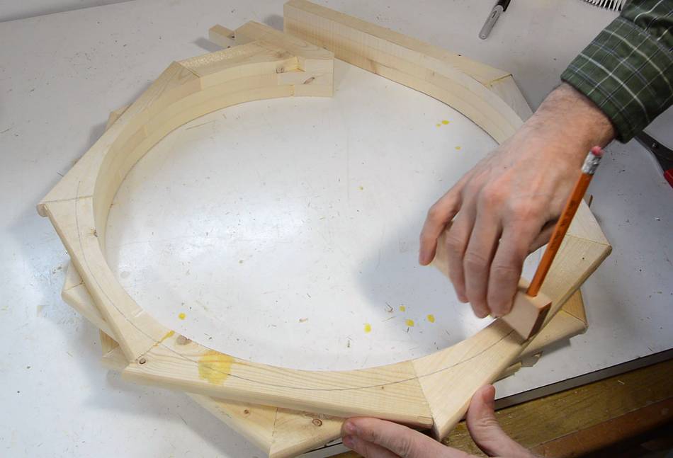
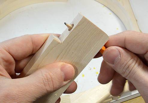 With the inside cut out, I made an offset marking tool out of a scrap of plywood
and marked a line 15 mm from the inside edge of the blower....
With the inside cut out, I made an offset marking tool out of a scrap of plywood
and marked a line 15 mm from the inside edge of the blower....
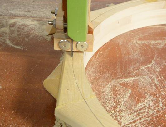 ... then cut that out on the bandsaw.
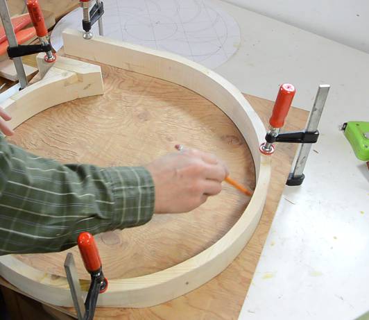 I then clamped the rotor housing on a piece of plywood. I used my
plywood template to mark where the motor's shaft needs to be and also
traced the outline of the housing onto the plywood.
I then clamped the rotor housing on a piece of plywood. I used my
plywood template to mark where the motor's shaft needs to be and also
traced the outline of the housing onto the plywood.
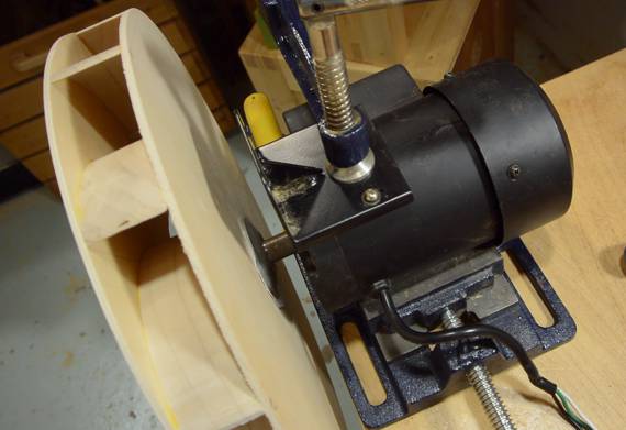
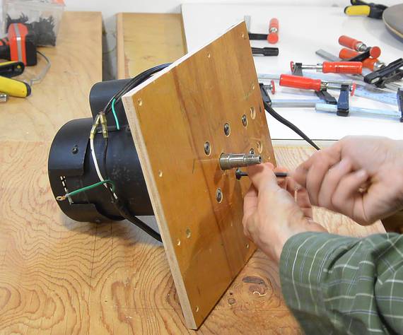 Lucky for me, this motor is a flange mount motor. Otherwise, I would have
had to make a small shelf for it. An 11 mm thick piece of
plywood to go between the back of the blower and the motor put
it at just the right distance back.
Lucky for me, this motor is a flange mount motor. Otherwise, I would have
had to make a small shelf for it. An 11 mm thick piece of
plywood to go between the back of the blower and the motor put
it at just the right distance back.
 Screwing on the housing edge. I should glue this on later, but for now I'm
only screwing it so I can still make changes.
Screwing on the housing edge. I should glue this on later, but for now I'm
only screwing it so I can still make changes.
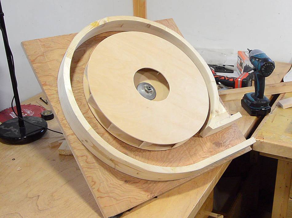 Still need a front panel for the housing.
Update 2017:
From recent experiments I realized it's not
ideal to have the housing get as close to the impeller as I have here,
so I ended up
modifying the shape slightly to make it quieter. I also made changes
to the plans to reflect this, so if you build
this dust collector, yours will be quieter to begin with.

 I used my plywood template to work out where the hole should go, then cut
that on the scroll saw.
I used my plywood template to work out where the hole should go, then cut
that on the scroll saw.
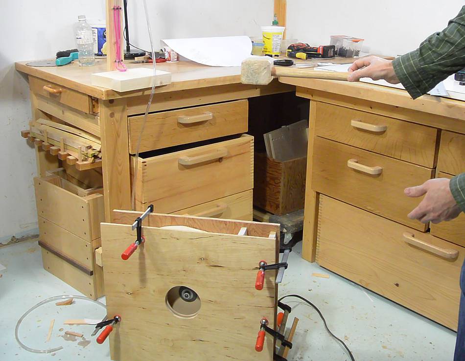
 For the first tests, I only put it together with clamps.
The blower blows surprisingly hard, and measuring the suction with my manometer, it's equivalent to a 36 cm water column, or about 14". That's quite a lot, substantially more than my big dust collector, and twice as much as my cheap dust collector
It's a lot of pressure for a dust collector type blower, but a vacuum cleaner or a ShopVac will typically develop about 150 cm of suction if airflow is blocked, about four times as much.
 The stream of air coming out of it is also quite powerful. Enough to
float the head of a wooden mallet about 45 cm above the outlet.
The stream of air coming out of it is also quite powerful. Enough to
float the head of a wooden mallet about 45 cm above the outlet.
A question that has come up on the YouTube video again and again
is "why not just use a furnace blower". The problem is, for a dust
collector, especially one with a cyclone, you need a lot of pressure.
A furnace blower will produce about 16 mm of pressure, which is about
one tenth as much as my cheap dust collector,
and one twentieth of this one.
Another question that comes up: Can a 1750 RPM motor be used? Not really. I built a blower using a 1750 rpm motor. I actually made that one larger than this one, but I only got 95 mm of pressure. Not enough for what I needed. If you halve the RPM, you need to double the diameter of the impeller to get the same pressure, which would make for a very large impeller with a slower motor.
I have often been asked for plans for this blower. I do have plans for it, as part of my small dust collector plans.
Next: Putting together a dust collector with this blower
 Two bucket cyclone
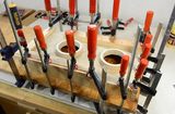 Manifold for the dust collector
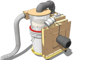
 Building a blower for integrated dust collection
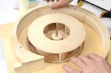 Blower impeller design experiments
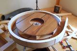 My first dust collector blower
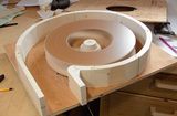 Blower design experiment
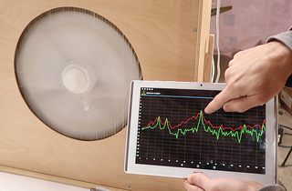 Measuring RPM with a spectrum analyzer app
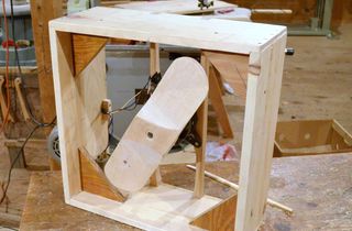 Building a box fan
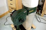 Cheap dust collector
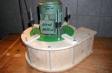
 How AC (induction)
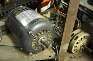 Where do you get your motors from?